2000 DODGE NEON instrument panel
[x] Cancel search: instrument panelPage 1 of 1285

GROUP TAB LOCATORINIntroductionINaIntroduction0Lubrication and Maintenance2Suspension3Differential and Driveline5Brakes6Clutch7Cooling8ABattery8BStarting8CCharging System8DIgnition System8EInstrument Panel and Systems8EaInstrument Panel and Systems8FAudio System8GHorns8HVehicle Speed Control System8JTurn Signal and Flashers8KWindshield Wipers and Washers8LLamps8LaLamps8MRestraint System8NElectrically Heated Systems8OPower Distribution Systems8PPower Door Locks8QImmobilizer System8SPower Windows8TPower Mirrors8TaPower Mirrors8UChime Warning/Reminder System8WWiring Diagrams - LHD and RHD9Engine11Exhaust System13Frame and Bumpers14Fuel System19Steering21Transaxle22Tires and Wheels23Body24Heating and Air Conditioning24aHeating and Air Conditioning25Emission Control Systems
Page 81 of 1285
DESCRIPTION AND OPERATION
BASE BRAKE SYSTEM OPERATION
When a vehicle needs to be stopped, the driver
applies the brake pedal. The brake pedal pushes the
input rod of the power brake booster into the booster.
The booster uses vacuum to ease pedal effort as force
is transferred through the booster to the master cyl-
inder. The booster's output rod pushes in the master
cylinder's primary and secondary pistons applying
hydraulic pressure through the chassis brake tubes
and proportioning valves (rear only) to the brakes at
each tire and wheel assembly.
Front disc brakes control the braking of the front
wheels; rear braking is controlled by rear drum
brakes as standard equipment. Rear disc brakes and
an antilock brake system (ABS) with traction control
are optional.
The hydraulic brake system is diagonally split on
both the non-antilock and antilock braking systems.
This means the left front and right rear brakes are
on one hydraulic circuit and the right front and left
rear are on the other.
Vehicles equipped with the optional antilock brake
system (ABS) use a system designated Mark 20e.
This system shares most base brake hardware used
on vehicles without ABS. A vehicle equipped with
ABS, however, uses a different master cylinder and
brake tubes. Also included in the ABS system is an
integrated control unit (ICU) and four wheel speed
sensors. These components are described in detail in
the ANTILOCK BRAKE SYSTEM section in this
group of the service manual. All vehicles with ABS
come standard with four-wheel-disc brakes and trac-
tion control.
The parking brakes are hand-operated. When
applied, the parking brake lever pulls on cables that
actuate brake shoes at each rear wheel. The parking
brake lever has an automatic adjusting feature that
takes up any excessive slack in the parking brake
cable system.
BASE BRAKE SYSTEM COMPONENTS
BRAKE PEDAL
A suspended-type brake pedal is used on this vehi-
cle. The pedal pivots on a shaft mounted in the pedal
support bracket under the instrument panel. The
pedal connects to the power brake booster input rod
and pushes it in when the pedal is applied.
The brake pedal and it's pad are serviceable sepa-
rately.
POWER BRAKE BOOSTER
There are two different power brake booster
designs, although externally they appear the same.
All vehicles use a 205 mm tandem diaphragm power
brake booster. The two boosters are internally tuned
differently depending on whether the vehicle is
equipped with the standard front disc/rear drum
brake combination or the optional front disc/rear disc
(four-wheel disc) brake combination. If the power
brake booster requires replacement, be sure it is
replaced with the correct part.
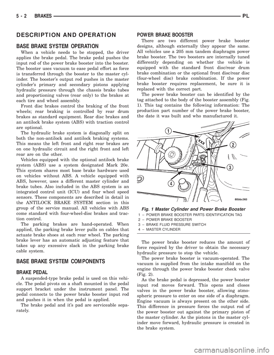
The power brake booster can be identified by the
tag attached to the body of the booster assembly (Fig.
1). This tag contains the following information: The
production part number of the power brake booster,
the date it was built and who manufactured it.
The power brake booster reduces the amount of
force required by the driver to obtain the necessary
hydraulic pressure to stop the vehicle.
The power brake booster is vacuum-operated. The
vacuum is supplied from the intake manifold on the
engine through the power brake booster check valve
(Fig. 2).
As the brake pedal is depressed, the power booster
input rod moves forward. This opens and closes
valves in the power brake booster, allowing atmo-
spheric pressure to enter on one side of a diaphragm.
Engine vacuum is always present on the other side.
This difference in pressure forces the output rod of
the power booster out against the primary piston of
the master cylinder. As the pistons in the master cyl-
inder move forward, hydraulic pressure is created in
the brake system.
Fig. 1 Master Cylinder and Power Brake Booster
1 ± POWER BRAKE BOOSTER PARTS IDENTIFICATION TAG
2 ± POWER BRAKE BOOSTER
3 ± BRAKE FLUID PRESSURE SWITCH
4 ± MASTER CYLINDER
5 - 2 BRAKESPL
Page 87 of 1285
RED BRAKE WARNING LAMP
The red BRAKE warning lamp is located in the
instrument panel cluster and illuminates when a low
brake fluid condition occurs or when the parking
brake lever is applied with the ignition key in the
ON position. In addition, the red BRAKE warning
lamp illuminates when the ignition switch is moved
from the OFF to the ON or CRANK position. This is
done to check the bulb's operation.
Problems with this system will generally be of the
type where the warning lamp fails to turn on when it
should, or remains on when it should not.
The red BRAKE warning lamp LED is supplied
with current anytime the ignition switch is ON. The
bulb is illuminated by completing the ground circuit
using any of the following components:
²the brake fluid level switch located in the mas-
ter cylinder reservoir
²the parking brake switch mounted on the park-
ing brake lever (Fig. 10)
²the ignition switch when the ignition switch is
first moved to the ON or CRANK position
²the mechanical instrument cluster (MIC) (with
ABS)
²the ABS electronic brake distribution (EBD)
The brake fluid level switch is located in the brake
fluid reservoir of the master cylinder assembly (Fig.
1). The purpose of the switch is to provide the driver
with an early warning that the brake fluid level inthe master cylinder reservoir has dropped below an
acceptable level.
As the fluid drops below the minimum level, the
fluid level switch closes and grounds the red BRAKE
warning lamp circuit. This turns on the red BRAKE
warning lamp. At this time, the master cylinder fluid
reservoir must be checked and filled to the full mark
with DOT 3 brake fluid. An abnormal loss of brake
fluid in the master cylinder fluid reservoir could be
caused by a leak in the hydraulic system. The entire
brake hydraulic system should be checked for evi-
dence of a leak.
The red BRAKE warning lamp can be turned on by
the MIC in the case where the ABS is experiencing a
problem where the amber ABS warning lamp needs
to be illuminated and cannot. The MIC will then illu-
minate the red BRAKE warning lamp.
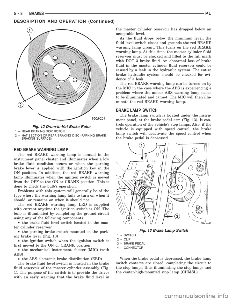
BRAKE LAMP SWITCH
The brake lamp switch is located under the instru-
ment panel, at the brake pedal arm (Fig. 13). It con-
trols operation of the vehicle's stop lamps. Also, if the
vehicle is equipped with speed control, the brake
lamp switch will deactivate the speed control when
the brake pedal is depressed.
When the brake pedal is depressed, the brake lamp
switch contacts are closed, completing the circuit to
the stop lamps, thus illuminating the stop lamps and
the center-high-mounted stop lamp (CHMSL).
Fig. 12 Drum-In-Hat Brake Rotor
1 ± REAR BRAKING DISK ROTOR
2 ± HAT SECTION OF REAR BRAKING DISC (PARKING BRAKE
BRAKING SURFACE)
Fig. 13 Brake Lamp Switch
1 ± SWITCH
2 ± CLIP
3 ± BRAKE PEDAL
4 ± CONNECTOR
5 - 8 BRAKESPL
DESCRIPTION AND OPERATION (Continued)
Page 104 of 1285
(10) If the vehicle is equipped with antilock
brakes, carefully push the power brake booster for-
ward until the booster contacts the ABS ICU mount-
ing bracket.
(11) If the vehicle does not have antilock brakes,
carefully push the power brake booster forward one
to two inches being careful not to stretch the brake
lines from the master cylinder to the brakes.
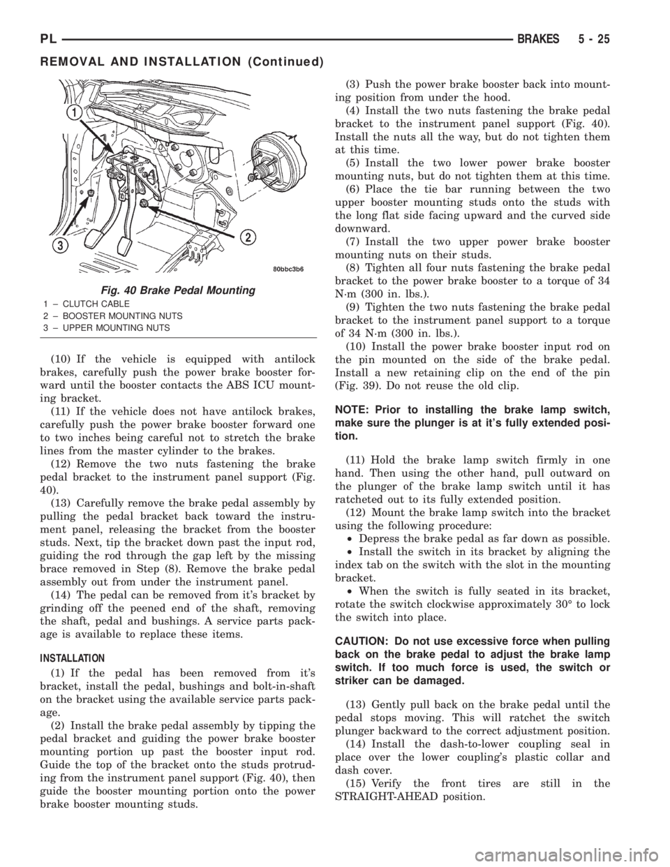
(12) Remove the two nuts fastening the brake
pedal bracket to the instrument panel support (Fig.
40).
(13) Carefully remove the brake pedal assembly by
pulling the pedal bracket back toward the instru-
ment panel, releasing the bracket from the booster
studs. Next, tip the bracket down past the input rod,
guiding the rod through the gap left by the missing
brace removed in Step (8). Remove the brake pedal
assembly out from under the instrument panel.
(14) The pedal can be removed from it's bracket by
grinding off the peened end of the shaft, removing
the shaft, pedal and bushings. A service parts pack-
age is available to replace these items.
INSTALLATION
(1) If the pedal has been removed from it's
bracket, install the pedal, bushings and bolt-in-shaft
on the bracket using the available service parts pack-
age.
(2) Install the brake pedal assembly by tipping the
pedal bracket and guiding the power brake booster
mounting portion up past the booster input rod.
Guide the top of the bracket onto the studs protrud-
ing from the instrument panel support (Fig. 40), then
guide the booster mounting portion onto the power
brake booster mounting studs.(3) Push the power brake booster back into mount-
ing position from under the hood.
(4) Install the two nuts fastening the brake pedal
bracket to the instrument panel support (Fig. 40).
Install the nuts all the way, but do not tighten them
at this time.
(5) Install the two lower power brake booster
mounting nuts, but do not tighten them at this time.
(6) Place the tie bar running between the two
upper booster mounting studs onto the studs with
the long flat side facing upward and the curved side
downward.
(7) Install the two upper power brake booster
mounting nuts on their studs.
(8) Tighten all four nuts fastening the brake pedal
bracket to the power brake booster to a torque of 34
N´m (300 in. lbs.).
(9) Tighten the two nuts fastening the brake pedal
bracket to the instrument panel support to a torque
of 34 N´m (300 in. lbs.).
(10) Install the power brake booster input rod on
the pin mounted on the side of the brake pedal.
Install a new retaining clip on the end of the pin
(Fig. 39). Do not reuse the old clip.
NOTE: Prior to installing the brake lamp switch,
make sure the plunger is at it's fully extended posi-
tion.
(11) Hold the brake lamp switch firmly in one
hand. Then using the other hand, pull outward on
the plunger of the brake lamp switch until it has
ratcheted out to its fully extended position.
(12) Mount the brake lamp switch into the bracket
using the following procedure:
²Depress the brake pedal as far down as possible.
²Install the switch in its bracket by aligning the
index tab on the switch with the slot in the mounting
bracket.
²When the switch is fully seated in its bracket,
rotate the switch clockwise approximately 30É to lock
the switch into place.
CAUTION: Do not use excessive force when pulling
back on the brake pedal to adjust the brake lamp
switch. If too much force is used, the switch or
striker can be damaged.
(13) Gently pull back on the brake pedal until the
pedal stops moving. This will ratchet the switch
plunger backward to the correct adjustment position.
(14) Install the dash-to-lower coupling seal in
place over the lower coupling's plastic collar and
dash cover.
(15) Verify the front tires are still in the
STRAIGHT-AHEAD position.
Fig. 40 Brake Pedal Mounting
1 ± CLUTCH CABLE
2 ± BOOSTER MOUNTING NUTS
3 ± UPPER MOUNTING NUTS
PLBRAKES 5 - 25
REMOVAL AND INSTALLATION (Continued)
Page 105 of 1285
(16) Reconnect the steering column lower coupling
to the steering column upper coupling (Fig. 38).
Install the coupling pinch bolt an tighten the pinch
bolt nut to a torque of 28 N´m (250 in. lbs.). Install
the pinch bolt retainer pin.
(17) Remove the steering wheel holder (Fig. 37).
(18) While looking under the instrument panel at
the lower coupling, rotate the steering wheel back-
and-forth to verify that the lower coupling does not
squeak against the dash-to-coupling seal.
(19) Reconnect the battery negative terminal.
(20) Check the stop lamps to verify they are oper-
ating properly and not staying on when the pedal is
in the released position.
(21) Road test the vehicle to ensure proper opera-
tion of the brakes.
WITH MANUAL TRANSAXLE
REMOVAL
(1) Remove the instrument panel. Refer to the
INSTRUMENT PANELS AND SYSTEMS group in
this service manual for the required procedure.
(2) Depress and hold the brake pedal while rotat-
ing the brake lamp switch (Fig. 39) in a counterclock-
wise direction approximately 30 degrees.
(3) Pull the switch rearward and remove it from
its mounting bracket.
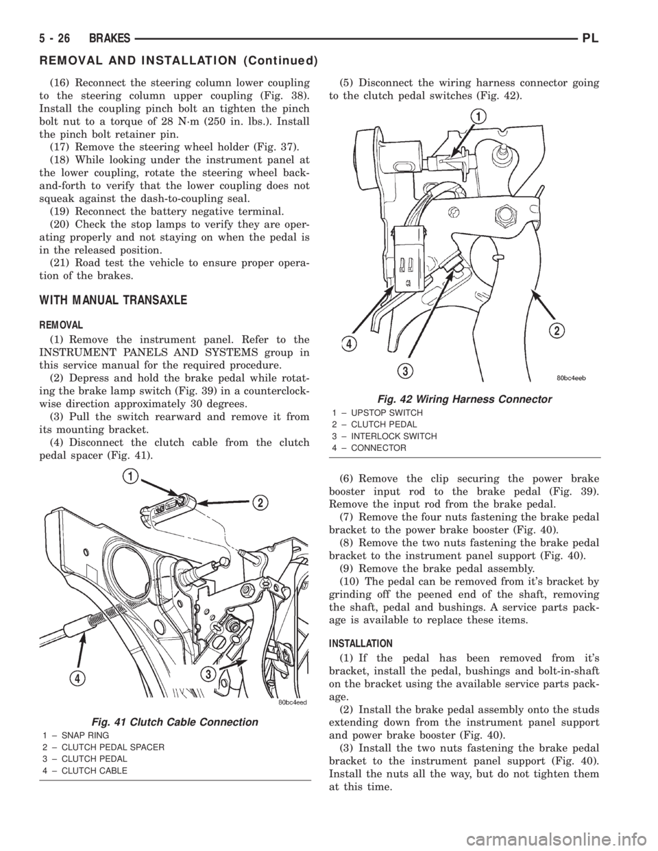
(4) Disconnect the clutch cable from the clutch
pedal spacer (Fig. 41).(5) Disconnect the wiring harness connector going
to the clutch pedal switches (Fig. 42).
(6) Remove the clip securing the power brake
booster input rod to the brake pedal (Fig. 39).
Remove the input rod from the brake pedal.
(7) Remove the four nuts fastening the brake pedal
bracket to the power brake booster (Fig. 40).
(8) Remove the two nuts fastening the brake pedal
bracket to the instrument panel support (Fig. 40).
(9) Remove the brake pedal assembly.
(10) The pedal can be removed from it's bracket by
grinding off the peened end of the shaft, removing
the shaft, pedal and bushings. A service parts pack-
age is available to replace these items.
INSTALLATION
(1) If the pedal has been removed from it's
bracket, install the pedal, bushings and bolt-in-shaft
on the bracket using the available service parts pack-
age.
(2) Install the brake pedal assembly onto the studs
extending down from the instrument panel support
and power brake booster (Fig. 40).
(3) Install the two nuts fastening the brake pedal
bracket to the instrument panel support (Fig. 40).
Install the nuts all the way, but do not tighten them
at this time.
Fig. 41 Clutch Cable Connection
1 ± SNAP RING
2 ± CLUTCH PEDAL SPACER
3 ± CLUTCH PEDAL
4 ± CLUTCH CABLE
Fig. 42 Wiring Harness Connector
1 ± UPSTOP SWITCH
2 ± CLUTCH PEDAL
3 ± INTERLOCK SWITCH
4 ± CONNECTOR
5 - 26 BRAKESPL
REMOVAL AND INSTALLATION (Continued)
Page 106 of 1285
(4) Install the power brake booster mounting nuts.
Tighten the four nuts fastening the brake pedal
bracket to the power brake booster to a torque of 34
N´m (300 in. lbs.).
(5) Tighten the two nuts fastening the brake pedal
bracket to the instrument panel support to a torque
of 34 N´m (300 in. lbs.).
(6) Connect the clutch cable to the clutch pedal
spacer on the pedal (Fig. 41).
(7) Connect the wiring harness connector going to
the clutch pedal switches (Fig. 42).
(8) Install the power brake booster input rod on
the pin mounted on the side of the brake pedal.
Install a new retaining clip on the end of the pin
(Fig. 39). Do not reuse the old clip.
NOTE: Prior to installing the brake lamp switch,
make sure the plunger is at it's fully extended posi-
tion.
(9) Hold the brake lamp switch firmly in one hand.
Then using the other hand, pull outward on the
plunger of the brake lamp switch until it has ratch-
eted out to its fully extended position.
(10) Mount the brake lamp switch into the bracket
using the following procedure:
²Depress the brake pedal as far down as possible.
²Install the switch in its bracket by aligning the
index tab on the switch with the slot in the mounting
bracket.
²When the switch is fully seated in its bracket,
rotate the switch clockwise approximately 30É to lock
the switch into place.
CAUTION: Do not use excessive force when pulling
back on the brake pedal to adjust the brake lamp
switch. If too much force is used, the switch or
striker can be damaged.
(11) Gently pull back on the brake pedal until the
pedal stops moving. This will ratchet the switch
plunger backward to the correct adjustment position.
(12) Install the instrument panel. Refer to the
INSTRUMENT PANELS AND SYSTEMS group in
this service manual for the required procedure.
(13) Check the stop lamps to verify they are oper-
ating properly and not staying on when the pedal is
in the released position.
(14) Road test the vehicle to ensure proper opera-
tion of the brakes.
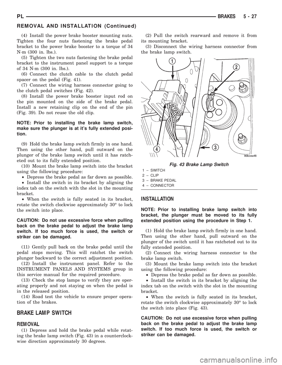
BRAKE LAMP SWITCH
REMOVAL
(1) Depress and hold the brake pedal while rotat-
ing the brake lamp switch (Fig. 43) in a counterclock-
wise direction approximately 30 degrees.(2) Pull the switch rearward and remove it from
its mounting bracket.
(3) Disconnect the wiring harness connector from
the brake lamp switch.
INSTALLATION
NOTE: Prior to installing brake lamp switch into
bracket, the plunger must be moved to its fully
extended position using the procedure in Step 1.
(1) Hold the brake lamp switch firmly in one hand.
Then using the other hand, pull outward on the
plunger of the switch until it has ratcheted out to its
fully extended position.
(2) Connect the wiring harness connector to the
brake lamp switch.
(3) Mount the brake lamp switch into the bracket
using the following procedure:
²Depress the brake pedal as far down as possible.
²Install the switch in its bracket by aligning the
index tab on the switch with the slot in the mounting
bracket.
²When the switch is fully seated in its bracket,
rotate the switch clockwise approximately 30É to lock
the switch into place (Fig. 43).
CAUTION: Do not use excessive force when pulling
back on the brake pedal to adjust the brake lamp
switch. If too much force is used, the switch or
striker can be damaged.
Fig. 43 Brake Lamp Switch
1 ± SWITCH
2 ± CLIP
3 ± BRAKE PEDAL
4 ± CONNECTOR
PLBRAKES 5 - 27
REMOVAL AND INSTALLATION (Continued)
Page 109 of 1285
(4) Fill the reservoir with fresh clean DOT 3 brake
fluid. Refer to BRAKE FLUID LEVEL CHECKING
in the SERVICE PROCEDURES section in this sec-
tion of this service manual group.
BRAKE FLUID LEVEL SWITCH
NOTE: Before proceeding with this procedure,
review SERVICE WARNINGS AND CAUTIONS at the
beginning of REMOVAL AND INSTALLATION in this
section.
REMOVAL
(1) Remove the vehicle wiring harness connector
from brake fluid level switch in master cylinder
brake fluid reservoir (Fig. 44).
(2) Push together the retaining tabs holding the
brake fluid level switch in place in the brake fluid
reservoir (Fig. 46).
(3) Pull the brake fluid level switch out the other
side of the reservoir.
INSTALLATION
(1) Align the brake fluid level switch with its
mounting hole on the left side of the master cylinder
brake fluid reservoir. Push the switch into the fluid
reservoir until the switch retaining tabs are
expanded on the other side of the reservoir, locking it
in place (Fig. 46).
(2) Connect the brake fluid level switch wiring
connector (Fig. 44).
POWER BRAKE BOOSTER
NOTE: Before proceeding with this procedure,
review SERVICE WARNINGS AND CAUTIONS at the
beginning of REMOVAL AND INSTALLATION in this
section.
REMOVAL
(1) Disconnect negative (ground) cable from the
battery and isolate the cable.
(2) Disconnect the positive cable from the battery,
then remove the battery from the battery tray. There
is one nut securing the clamp on the backside of the
battery holding it in place.
(3) Remove the one nut and one bolt securing the
air cleaner box in place, then disconnect the wiring
harness connector at the air inlet sensor.
(4) Lift the air cleaner box upward enough to clear
its grommeted alignment post (Fig. 48), then move
the air cleaner box forward just enough to access the
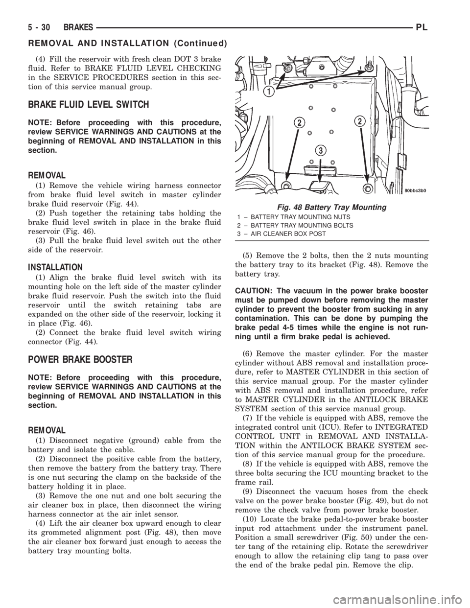
battery tray mounting bolts.(5) Remove the 2 bolts, then the 2 nuts mounting
the battery tray to its bracket (Fig. 48). Remove the
battery tray.
CAUTION: The vacuum in the power brake booster
must be pumped down before removing the master
cylinder to prevent the booster from sucking in any
contamination. This can be done by pumping the
brake pedal 4-5 times while the engine is not run-
ning until a firm brake pedal is achieved.
(6) Remove the master cylinder. For the master
cylinder without ABS removal and installation proce-
dure, refer to MASTER CYLINDER in this section of
this service manual group. For the master cylinder
with ABS removal and installation procedure, refer
to MASTER CYLINDER in the ANTILOCK BRAKE
SYSTEM section of this service manual group.
(7) If the vehicle is equipped with ABS, remove the
integrated control unit (ICU). Refer to INTEGRATED
CONTROL UNIT in REMOVAL AND INSTALLA-
TION within the ANTILOCK BRAKE SYSTEM sec-
tion of this service manual group for the procedure.
(8) If the vehicle is equipped with ABS, remove the
three bolts securing the ICU mounting bracket to the
frame rail.
(9) Disconnect the vacuum hoses from the check
valve on the power brake booster (Fig. 49), but do not
remove the check valve from power brake booster.
(10) Locate the brake pedal-to-power brake booster
input rod attachment under the instrument panel.
Position a small screwdriver (Fig. 50) under the cen-
ter tang of the retaining clip. Rotate the screwdriver
enough to allow the retaining clip tang to pass over
the end of the brake pedal pin. Remove the clip.
Fig. 48 Battery Tray Mounting
1 ± BATTERY TRAY MOUNTING NUTS
2 ± BATTERY TRAY MOUNTING BOLTS
3 ± AIR CLEANER BOX POST
5 - 30 BRAKESPL
REMOVAL AND INSTALLATION (Continued)
Page 110 of 1285
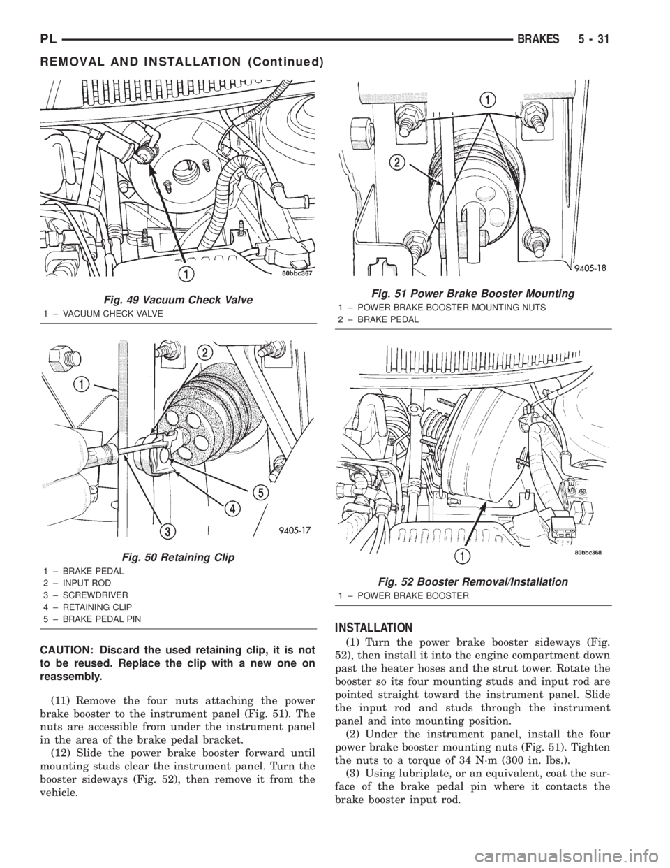
CAUTION: Discard the used retaining clip, it is not
to be reused. Replace the clip with a new one on
reassembly.
(11) Remove the four nuts attaching the power
brake booster to the instrument panel (Fig. 51). The
nuts are accessible from under the instrument panel
in the area of the brake pedal bracket.
(12) Slide the power brake booster forward until
mounting studs clear the instrument panel. Turn the
booster sideways (Fig. 52), then remove it from the
vehicle.
INSTALLATION
(1) Turn the power brake booster sideways (Fig.
52), then install it into the engine compartment down
past the heater hoses and the strut tower. Rotate the
booster so its four mounting studs and input rod are
pointed straight toward the instrument panel. Slide
the input rod and studs through the instrument
panel and into mounting position.
(2) Under the instrument panel, install the four
power brake booster mounting nuts (Fig. 51). Tighten
the nuts to a torque of 34 N´m (300 in. lbs.).
(3) Using lubriplate, or an equivalent, coat the sur-
face of the brake pedal pin where it contacts the
brake booster input rod.
Fig. 49 Vacuum Check Valve
1 ± VACUUM CHECK VALVE
Fig. 50 Retaining Clip
1 ± BRAKE PEDAL
2 ± INPUT ROD
3 ± SCREWDRIVER
4 ± RETAINING CLIP
5 ± BRAKE PEDAL PIN
Fig. 51 Power Brake Booster Mounting
1 ± POWER BRAKE BOOSTER MOUNTING NUTS
2 ± BRAKE PEDAL
Fig. 52 Booster Removal/Installation
1 ± POWER BRAKE BOOSTER
PLBRAKES 5 - 31
REMOVAL AND INSTALLATION (Continued)