2000 DODGE NEON instrument panel
[x] Cancel search: instrument panelPage 258 of 1285
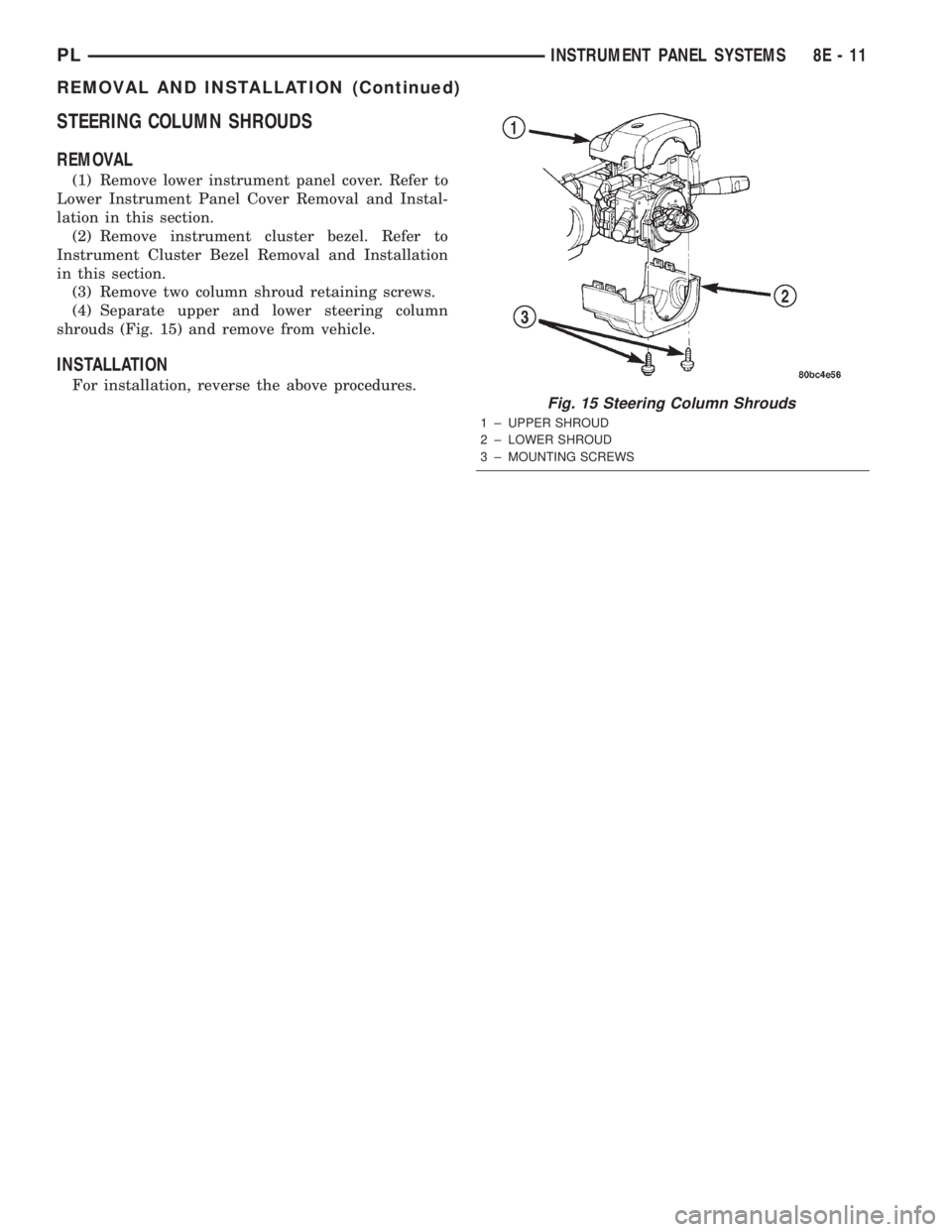
STEERING COLUMN SHROUDS
REMOVAL
(1) Remove lower instrument panel cover. Refer to
Lower Instrument Panel Cover Removal and Instal-
lation in this section.
(2) Remove instrument cluster bezel. Refer to
Instrument Cluster Bezel Removal and Installation
in this section.
(3) Remove two column shroud retaining screws.
(4) Separate upper and lower steering column
shrouds (Fig. 15) and remove from vehicle.
INSTALLATION
For installation, reverse the above procedures.
Fig. 15 Steering Column Shrouds
1 ± UPPER SHROUD
2 ± LOWER SHROUD
3 ± MOUNTING SCREWS
PLINSTRUMENT PANEL SYSTEMS 8E - 11
REMOVAL AND INSTALLATION (Continued)
Page 260 of 1285
INSTRUMENT PANEL AND SYSTEMS
TABLE OF CONTENTS
page page
DIAGNOSIS AND TESTING
HEADLAMP LEVELING SWITCH..............1
INSTRUMENT PANEL AND COMPONENTS.....1
REMOVAL AND INSTALLATION
HEADLAMP LEVELING SWITCH..............2INSTRUMENT PANEL ± R. H. D..............3
SPECIFICATIONS
TORQUE SPECIFICATIONS..................9
DIAGNOSIS AND TESTING
HEADLAMP LEVELING SWITCH
(1) Remove the headlamp leveling switch from the
instrument panel and disconnect the wire harness
connector from the switch. Refer to Wiring Diagrams
for the proper wire circuits and the wire connector
connections.
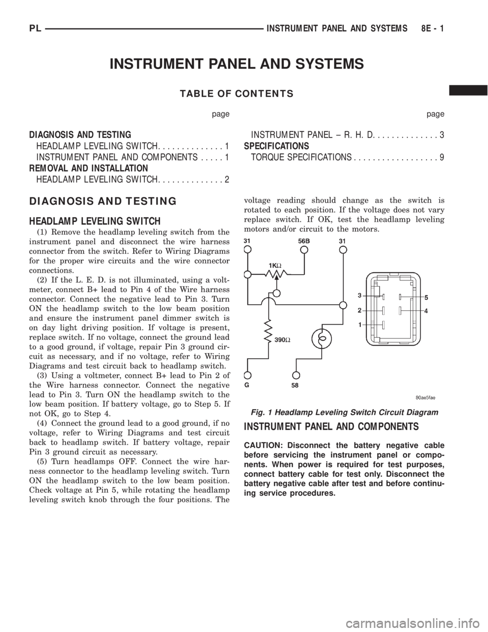
(2) If the L. E. D. is not illuminated, using a volt-
meter, connect B+ lead to Pin 4 of the Wire harness
connector. Connect the negative lead to Pin 3. Turn
ON the headlamp switch to the low beam position
and ensure the instrument panel dimmer switch is
on day light driving position. If voltage is present,
replace switch. If no voltage, connect the ground lead
to a good ground, if voltage, repair Pin 3 ground cir-
cuit as necessary, and if no voltage, refer to Wiring
Diagrams and test circuit back to headlamp switch.
(3) Using a voltmeter, connect B+ lead to Pin 2 of
the Wire harness connector. Connect the negative
lead to Pin 3. Turn ON the headlamp switch to the
low beam position. If battery voltage, go to Step 5. If
not OK, go to Step 4.
(4) Connect the ground lead to a good ground, if no
voltage, refer to Wiring Diagrams and test circuit
back to headlamp switch. If battery voltage, repair
Pin 3 ground circuit as necessary.
(5) Turn headlamps OFF. Connect the wire har-
ness connector to the headlamp leveling switch. Turn
ON the headlamp switch to the low beam position.
Check voltage at Pin 5, while rotating the headlamp
leveling switch knob through the four positions. Thevoltage reading should change as the switch is
rotated to each position. If the voltage does not vary
replace switch. If OK, test the headlamp leveling
motors and/or circuit to the motors.
INSTRUMENT PANEL AND COMPONENTS
CAUTION: Disconnect the battery negative cable
before servicing the instrument panel or compo-
nents. When power is required for test purposes,
connect battery cable for test only. Disconnect the
battery negative cable after test and before continu-
ing service procedures.
Fig. 1 Headlamp Leveling Switch Circuit Diagram
PLINSTRUMENT PANEL AND SYSTEMS 8E - 1
Page 261 of 1285
REMOVAL AND INSTALLATION
HEADLAMP LEVELING SWITCH
REMOVAL
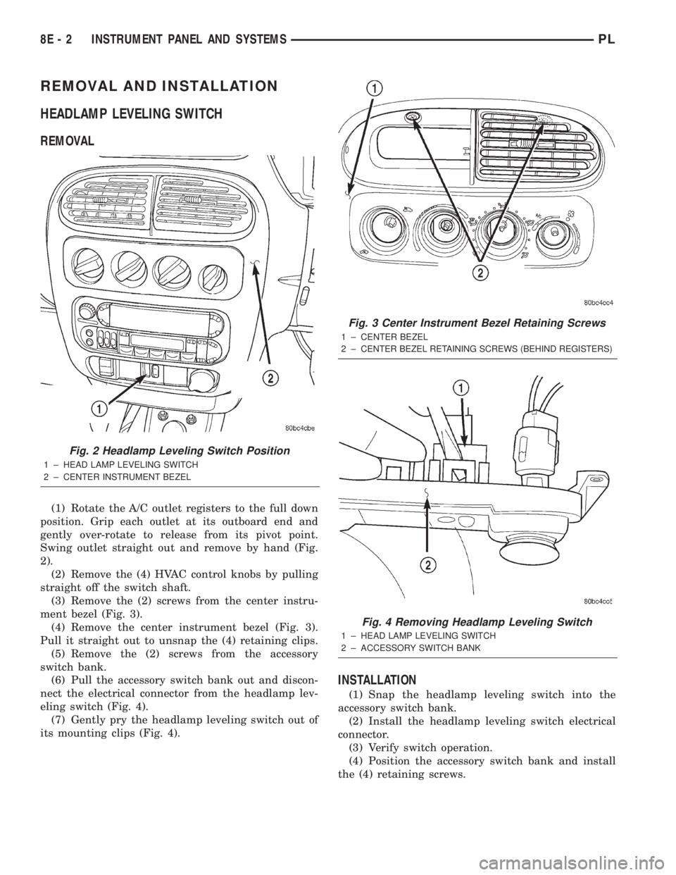
(1) Rotate the A/C outlet registers to the full down
position. Grip each outlet at its outboard end and
gently over-rotate to release from its pivot point.
Swing outlet straight out and remove by hand (Fig.
2).
(2) Remove the (4) HVAC control knobs by pulling
straight off the switch shaft.
(3) Remove the (2) screws from the center instru-
ment bezel (Fig. 3).
(4) Remove the center instrument bezel (Fig. 3).
Pull it straight out to unsnap the (4) retaining clips.
(5) Remove the (2) screws from the accessory
switch bank.
(6) Pull the accessory switch bank out and discon-
nect the electrical connector from the headlamp lev-
eling switch (Fig. 4).
(7) Gently pry the headlamp leveling switch out of
its mounting clips (Fig. 4).
INSTALLATION
(1) Snap the headlamp leveling switch into the
accessory switch bank.
(2) Install the headlamp leveling switch electrical
connector.
(3) Verify switch operation.
(4) Position the accessory switch bank and install
the (4) retaining screws.
Fig. 2 Headlamp Leveling Switch Position
1 ± HEAD LAMP LEVELING SWITCH
2 ± CENTER INSTRUMENT BEZEL
Fig. 3 Center Instrument Bezel Retaining Screws
1 ± CENTER BEZEL
2±
CENTER BEZEL RETAINING SCREWS (BEHIND REGISTERS)
Fig. 4 Removing Headlamp Leveling Switch
1 ± HEAD LAMP LEVELING SWITCH
2 ± ACCESSORY SWITCH BANK
8E - 2 INSTRUMENT PANEL AND SYSTEMSPL
Page 262 of 1285
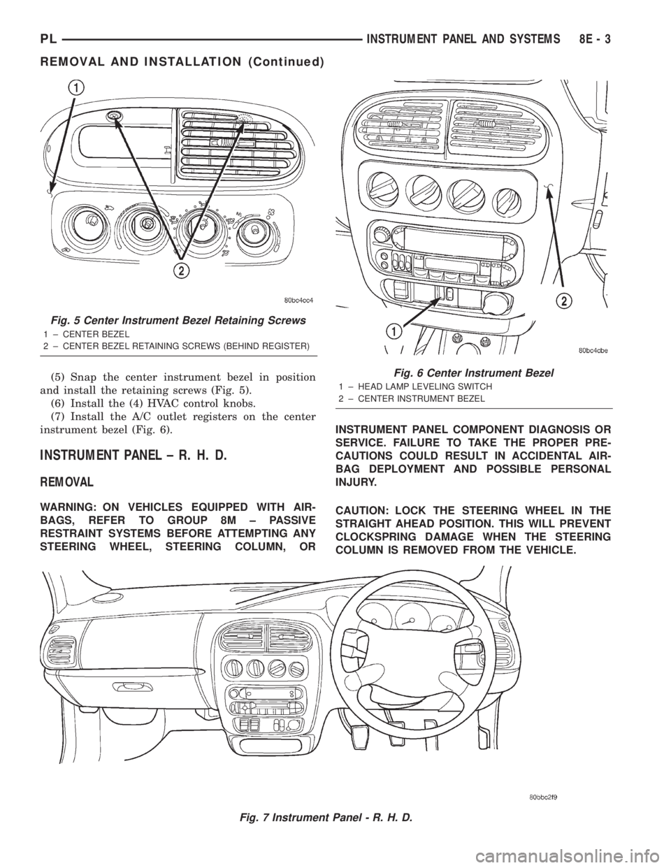
(5) Snap the center instrument bezel in position
and install the retaining screws (Fig. 5).
(6) Install the (4) HVAC control knobs.
(7) Install the A/C outlet registers on the center
instrument bezel (Fig. 6).
INSTRUMENT PANEL ± R. H. D.
REMOVAL
WARNING: ON VEHICLES EQUIPPED WITH AIR-
BAGS, REFER TO GROUP 8M ± PASSIVE
RESTRAINT SYSTEMS BEFORE ATTEMPTING ANY
STEERING WHEEL, STEERING COLUMN, ORINSTRUMENT PANEL COMPONENT DIAGNOSIS OR
SERVICE. FAILURE TO TAKE THE PROPER PRE-
CAUTIONS COULD RESULT IN ACCIDENTAL AIR-
BAG DEPLOYMENT AND POSSIBLE PERSONAL
INJURY.
CAUTION: LOCK THE STEERING WHEEL IN THE
STRAIGHT AHEAD POSITION. THIS WILL PREVENT
CLOCKSPRING DAMAGE WHEN THE STEERING
COLUMN IS REMOVED FROM THE VEHICLE.
Fig. 7 Instrument Panel - R. H. D.
Fig. 5 Center Instrument Bezel Retaining Screws
1 ± CENTER BEZEL
2 ± CENTER BEZEL RETAINING SCREWS (BEHIND REGISTER)
Fig. 6 Center Instrument Bezel
1 ± HEAD LAMP LEVELING SWITCH
2 ± CENTER INSTRUMENT BEZEL
PLINSTRUMENT PANEL AND SYSTEMS 8E - 3
REMOVAL AND INSTALLATION (Continued)
Page 263 of 1285
(1) Disconnect the negative battery cable.
(2) Remove the floor console. Refer to Group 23,
Body for the procedure.
(3) Remove the right and left side instrument
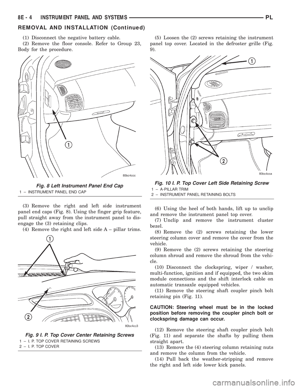
panel end caps (Fig. 8). Using the finger grip feature,
pull straight away from the instrument panel to dis-
engage the (3) retaining clips.
(4) Remove the right and left side A ± pillar trims.(5) Loosen the (2) screws retaining the instrument
panel top cover. Located in the defroster grille (Fig.
9).
(6) Using the heel of both hands, lift up to unclip
and remove the instrument panel top cover.
(7) Unclip and remove the instrument cluster
bezel.
(8) Remove the (2) screws retaining the lower
steering column cover and remove the cover from the
vehicle.
(9) Remove the (2) screws retaining the steering
column shroud and remove the shroud from the vehi-
cle.
(10) Disconnect the clockspring, wiper / washer,
multi-function, ignition and if equipped, the two skim
module connections and the shift interlock cable on
automatic transaxle equipped vehicles.
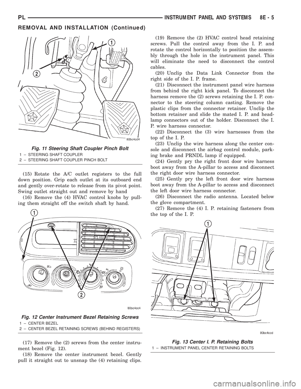
(11) Remove the steering shaft coupler pinch bolt
retaining pin (Fig. 11).
CAUTION: Steering wheel must be in the locked
position before removing the coupler pinch bolt or
clockspring damage can occur.
(12) Remove the steering shaft coupler pinch bolt
(Fig. 11) and separate the shafts by pulling them
straight apart.
(13) Remove the (4) steering column retaining nuts
and remove the column from the vehicle.
(14) Pull back the weather-stripping and remove
the right and left side lower kick panels.
Fig. 8 Left Instrument Panel End Cap
1 ± INSTRUMENT PANEL END CAP
Fig. 9 I. P. Top Cover Center Retaining Screws
1 ± I. P. TOP COVER RETAINING SCREWS
2 ± I. P. TOP COVER
Fig. 10 I. P. Top Cover Left Side Retaining Screw
1 ± A-PILLAR TRIM
2 ± INSTRUMENT PANEL RETAINING BOLTS
8E - 4 INSTRUMENT PANEL AND SYSTEMSPL
REMOVAL AND INSTALLATION (Continued)
Page 264 of 1285
(15) Rotate the A/C outlet registers to the full
down position. Grip each outlet at its outboard end
and gently over-rotate to release from its pivot point.
Swing outlet straight out and remove by hand
(16) Remove the (4) HVAC control knobs by pull-
ing them straight off the switch shaft by hand.
(17) Remove the (2) screws from the center instru-
ment bezel (Fig. 12).
(18) Remove the center instrument bezel. Gently
pull it straight out to unsnap the (4) retaining clips.(19) Remove the (2) HVAC control head retaining
screws. Pull the control away from the I. P. and
rotate the control horizontally to position the assem-
bly through the hole in the instrument panel. This
will eliminate the need to disconnect the control
cables.
(20) Unclip the Data Link Connector from the
right side of the I. P. frame.
(21) Disconnect the instrument panel wire harness
from behind the right kick panel. To disconnect the
harness remove the (2) screws retaining the I. P. con-
nector to the steering column casting. Remove the
plastic clips from the connector retainer. Unclip the
bottom retainer and slide the mated I. P. and head-
lamp connectors out of the holder. Disconnect the I.
P. wire harness connector.
(22) Disconnect the (3) wire harnesses from the
top of the I. P.
(23) Unclip the wire harness along the center con-
sole and disconnect the airbag control module, park-
ing brake and PRNDL lamp if equipped.
(24) Gently pry the right front door wire harness
boot away from the A-pillar to access and disconnect
the right door wire harness connector.
(25) Gently pry the left front door wire harness
boot away from the A-pillar to access and disconnect
the left door wire harness connector.
(26) Disconnect the radio antenna. Located below
the glove compartment.
(27) Remove the (4) I. P. retaining fasteners from
the top of the I. P.
Fig. 11 Steering Shaft Coupler Pinch Bolt
1 ± STEERING SHAFT COUPLER
2 ± STEERING SHAFT COUPLER PINCH BOLT
Fig. 12 Center Instrument Bezel Retaining Screws
1 ± CENTER BEZEL
2±
CENTER BEZEL RETAINING SCREWS (BEHIND REGISTERS)
Fig. 13 Center I. P. Retaining Bolts
1 ± INSTRUMENT PANEL CENTER RETAINING BOLTS
PLINSTRUMENT PANEL AND SYSTEMS 8E - 5
REMOVAL AND INSTALLATION (Continued)
Page 265 of 1285
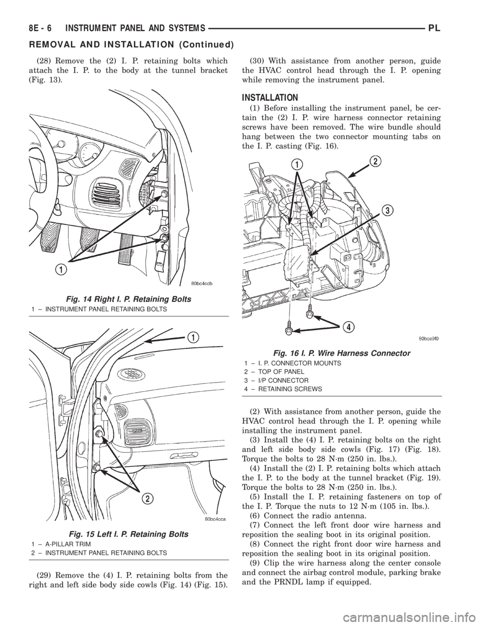
(28) Remove the (2) I. P. retaining bolts which
attach the I. P. to the body at the tunnel bracket
(Fig. 13).
(29) Remove the (4) I. P. retaining bolts from the
right and left side body side cowls (Fig. 14) (Fig. 15).(30) With assistance from another person, guide
the HVAC control head through the I. P. opening
while removing the instrument panel.
INSTALLATION
(1) Before installing the instrument panel, be cer-
tain the (2) I. P. wire harness connector retaining
screws have been removed. The wire bundle should
hang between the two connector mounting tabs on
the I. P. casting (Fig. 16).
(2) With assistance from another person, guide the
HVAC control head through the I. P. opening while
installing the instrument panel.
(3) Install the (4) I. P. retaining bolts on the right
and left side body side cowls (Fig. 17) (Fig. 18).
Torque the bolts to 28 N´m (250 in. lbs.).
(4) Install the (2) I. P. retaining bolts which attach
the I. P. to the body at the tunnel bracket (Fig. 19).
Torque the bolts to 28 N´m (250 in. lbs.).
(5) Install the I. P. retaining fasteners on top of
the I. P. Torque the nuts to 12 N´m (105 in. lbs.).
(6) Connect the radio antenna.
(7) Connect the left front door wire harness and
reposition the sealing boot in its original position.
(8) Connect the right front door wire harness and
reposition the sealing boot in its original position.
(9) Clip the wire harness along the center console
and connect the airbag control module, parking brake
and the PRNDL lamp if equipped.
Fig. 14 Right I. P. Retaining Bolts
1 ± INSTRUMENT PANEL RETAINING BOLTS
Fig. 15 Left I. P. Retaining Bolts
1 ± A-PILLAR TRIM
2 ± INSTRUMENT PANEL RETAINING BOLTS
Fig. 16 I. P. Wire Harness Connector
1 ± I. P. CONNECTOR MOUNTS
2 ± TOP OF PANEL
3 ± I/P CONNECTOR
4 ± RETAINING SCREWS
8E - 6 INSTRUMENT PANEL AND SYSTEMSPL
REMOVAL AND INSTALLATION (Continued)
Page 266 of 1285
(10) Connect the (3) wire harnesses on the top of
the I. P.
(11) Connect the I. P. wire harness and secure in
place by attaching the connectors to the steering col-
umn casting with (2) retaining screws. Clip the har-ness retainer at the bottom of the holder and secure
with (2) retainer clips.
(12) Clip the Data Link Connector on the right
side of the I. P. frame.
(13) Install the HVAC control head retaining
screws.
(14) Install the center instrument bezel.
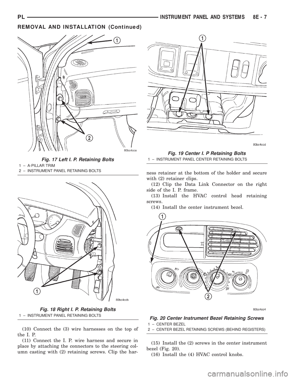
(15) Install the (2) screws in the center instrument
bezel (Fig. 20).
(16) Install the (4) HVAC control knobs.
Fig. 17 Left I. P. Retaining Bolts
1 ± A-PILLAR TRIM
2 ± INSTRUMENT PANEL RETAINING BOLTS
Fig. 18 Right I. P. Retaining Bolts
1 ± INSTRUMENT PANEL RETAINING BOLTS
Fig. 19 Center I. P Retaining Bolts
1 ± INSTRUMENT PANEL CENTER RETAINING BOLTS
Fig. 20 Center Instrument Bezel Retaining Screws
1 ± CENTER BEZEL
2±
CENTER BEZEL RETAINING SCREWS (BEHIND REGISTERS)
PLINSTRUMENT PANEL AND SYSTEMS 8E - 7
REMOVAL AND INSTALLATION (Continued)