2000 DODGE NEON service indicator
[x] Cancel search: service indicatorPage 8 of 1285

JUMP STARTING, TOWING, AND HOISTING
TABLE OF CONTENTS
page page
DESCRIPTION AND OPERATION
JUMP STARTING PROCEDURE...............7
TOWING RECOMMENDATIONS...............7
HOISTING RECOMMENDATIONS.............7SERVICE PROCEDURES
JUMP STARTING PROCEDURE...............7
TOWING RECOMMENDATIONS...............8
HOISTING RECOMMENDATIONS.............9
DESCRIPTION AND OPERATION
JUMP STARTING PROCEDURE
Describes the procedure for starting a disable vehi-
cle.
TOWING RECOMMENDATIONS
Describes the recommended towing procedures.
HOISTING RECOMMENDATIONS
Describes the location of hoisting and jacking
points so that the vehicle can be lifted by a floor jack
or hoist.
SERVICE PROCEDURES
JUMP STARTING PROCEDURE
WARNING: REVIEW ALL SAFETY PRECAUTIONS
AND WARNINGS IN GROUP 8A, BATTERY/START-
ING/CHARGING SYSTEMS DIAGNOSTICS. DO NOT
JUMP START A FROZEN BATTERY, PERSONAL
INJURY CAN RESULT. DO NOT JUMP START WHEN
MAINTENANCE FREE BATTERY INDICATOR DOT IS
YELLOW OR BRIGHT COLOR. DO NOT JUMP
START A VEHICLE WHEN THE BATTERY FLUID IS
BELOW THE TOP OF LEAD PLATES. DO NOT
ALLOW JUMPER CABLE CLAMPS TO TOUCH
EACH OTHER WHEN CONNECTED TO A BOOSTER
SOURCE. DO NOT USE OPEN FLAME NEAR BAT-
TERY. REMOVE METALLIC JEWELRY WORN ON
HANDS OR WRISTS TO AVOID INJURY BY ACCI-
DENTAL ARCING OF BATTERY CURRENT. WHEN
USING A HIGH OUTPUT BOOSTING DEVICE, DO
NOT ALLOW BATTERY VOLTAGE TO EXCEED 16
VOLTS. REFER TO INSTRUCTIONS PROVIDED
WITH DEVICE BEING USED.
CAUTION: When using another vehicle as a
booster, do not allow vehicles to touch. Electrical
systems can be damaged on either vehicle.
TO JUMP START A DISABLED VEHICLE:
(1) Raise hood on disabled vehicle and visually
inspect engine compartment for:
²Battery cable clamp condition, clean if necessary.
²Frozen battery.
²Yellow or bright color test indicator, if equipped.
²Low battery fluid level.
²Generator drive belt condition and tension.
²Fuel fumes or leakage, correct if necessary.
CAUTION: If the cause of starting problem on dis-
abled vehicle is severe, damage to booster vehicle
charging system can result.
(2) When using another vehicle as a booster
source, park the booster vehicle within cable reach.
Turn off all accessories, set the parking brake, place
the automatic transmission in PARK or the manual
transmission in NEUTRAL and turn the ignition
OFF.
(3) On disabled vehicle, place gear selector in park
or neutral and set park brake. Turn off all accesso-
ries.
(4) Connect jumper cables to booster battery. RED
clamp to positive terminal (+). BLACK clamp to neg-
ative terminal (-). DO NOT allow clamps at opposite
end of cables to touch, electrical arc will result.
Review all warnings in this procedure.
(5) On disabled vehicle, connect RED jumper cable
clamp to positive (+) terminal. Connect BLACK
jumper cable clamp to engine ground as close to the
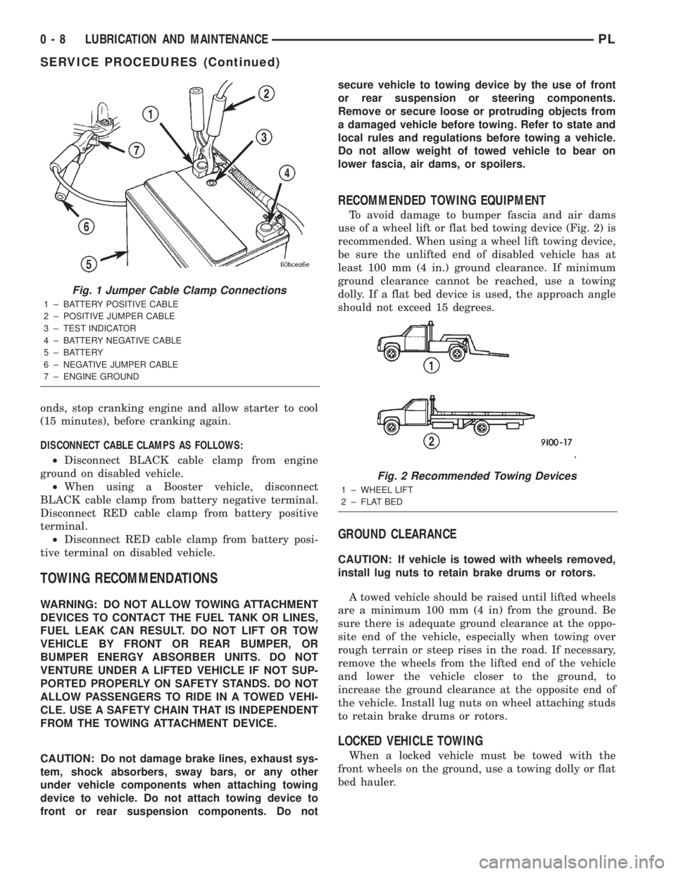
ground cable attaching point as possible (Fig. 1).
(6) Start the engine in the vehicle which has the
booster battery, let the engine idle a few minutes,
then start the engine in the vehicle with the dis-
charged battery.
CAUTION: Do not crank starter motor on disabled
vehicle for more than 15 seconds, starter will over-
heat and could fail.
(7) Allow battery in disabled vehicle to charge to
at least 12.4 volts (75% charge) before attempting to
start engine. If engine does not start within 15 sec-
PLLUBRICATION AND MAINTENANCE 0 - 7
Page 9 of 1285
onds, stop cranking engine and allow starter to cool
(15 minutes), before cranking again.
DISCONNECT CABLE CLAMPS AS FOLLOWS:
²Disconnect BLACK cable clamp from engine
ground on disabled vehicle.
²When using a Booster vehicle, disconnect
BLACK cable clamp from battery negative terminal.
Disconnect RED cable clamp from battery positive
terminal.
²Disconnect RED cable clamp from battery posi-
tive terminal on disabled vehicle.
TOWING RECOMMENDATIONS
WARNING: DO NOT ALLOW TOWING ATTACHMENT
DEVICES TO CONTACT THE FUEL TANK OR LINES,
FUEL LEAK CAN RESULT. DO NOT LIFT OR TOW
VEHICLE BY FRONT OR REAR BUMPER, OR
BUMPER ENERGY ABSORBER UNITS. DO NOT
VENTURE UNDER A LIFTED VEHICLE IF NOT SUP-
PORTED PROPERLY ON SAFETY STANDS. DO NOT
ALLOW PASSENGERS TO RIDE IN A TOWED VEHI-
CLE. USE A SAFETY CHAIN THAT IS INDEPENDENT
FROM THE TOWING ATTACHMENT DEVICE.
CAUTION: Do not damage brake lines, exhaust sys-
tem, shock absorbers, sway bars, or any other
under vehicle components when attaching towing
device to vehicle. Do not attach towing device to
front or rear suspension components. Do notsecure vehicle to towing device by the use of front
or rear suspension or steering components.
Remove or secure loose or protruding objects from
a damaged vehicle before towing. Refer to state and
local rules and regulations before towing a vehicle.
Do not allow weight of towed vehicle to bear on
lower fascia, air dams, or spoilers.
RECOMMENDED TOWING EQUIPMENT
To avoid damage to bumper fascia and air dams
use of a wheel lift or flat bed towing device (Fig. 2) is
recommended. When using a wheel lift towing device,
be sure the unlifted end of disabled vehicle has at
least 100 mm (4 in.) ground clearance. If minimum
ground clearance cannot be reached, use a towing
dolly. If a flat bed device is used, the approach angle
should not exceed 15 degrees.
GROUND CLEARANCE
CAUTION: If vehicle is towed with wheels removed,
install lug nuts to retain brake drums or rotors.
A towed vehicle should be raised until lifted wheels
are a minimum 100 mm (4 in) from the ground. Be
sure there is adequate ground clearance at the oppo-
site end of the vehicle, especially when towing over
rough terrain or steep rises in the road. If necessary,
remove the wheels from the lifted end of the vehicle
and lower the vehicle closer to the ground, to
increase the ground clearance at the opposite end of
the vehicle. Install lug nuts on wheel attaching studs
to retain brake drums or rotors.
LOCKED VEHICLE TOWING
When a locked vehicle must be towed with the
front wheels on the ground, use a towing dolly or flat
bed hauler.
Fig. 1 Jumper Cable Clamp Connections
1 ± BATTERY POSITIVE CABLE
2 ± POSITIVE JUMPER CABLE
3 ± TEST INDICATOR
4 ± BATTERY NEGATIVE CABLE
5 ± BATTERY
6 ± NEGATIVE JUMPER CABLE
7 ± ENGINE GROUND
Fig. 2 Recommended Towing Devices
1 ± WHEEL LIFT
2 ± FLAT BED
0 - 8 LUBRICATION AND MAINTENANCEPL
SERVICE PROCEDURES (Continued)
Page 92 of 1285
Some discoloration or wear of the rotor surface is
normal and does not require resurfacing when lin-
ings are replaced. If cracks or burned spots are evi-
dent, the rotor must be replaced.
ROTOR MINIMUM THICKNESS
Measure rotor thickness at the center of the brake
shoe contact surface. Replace the rotor if it is worn
below minimum thickness or if machining the rotor
will cause its thickness to fall below specifications.
CAUTION: Do not machine the rotor if it will cause
the rotor to fall below minimum thickness.
Minimum thickness specifications are cast on the
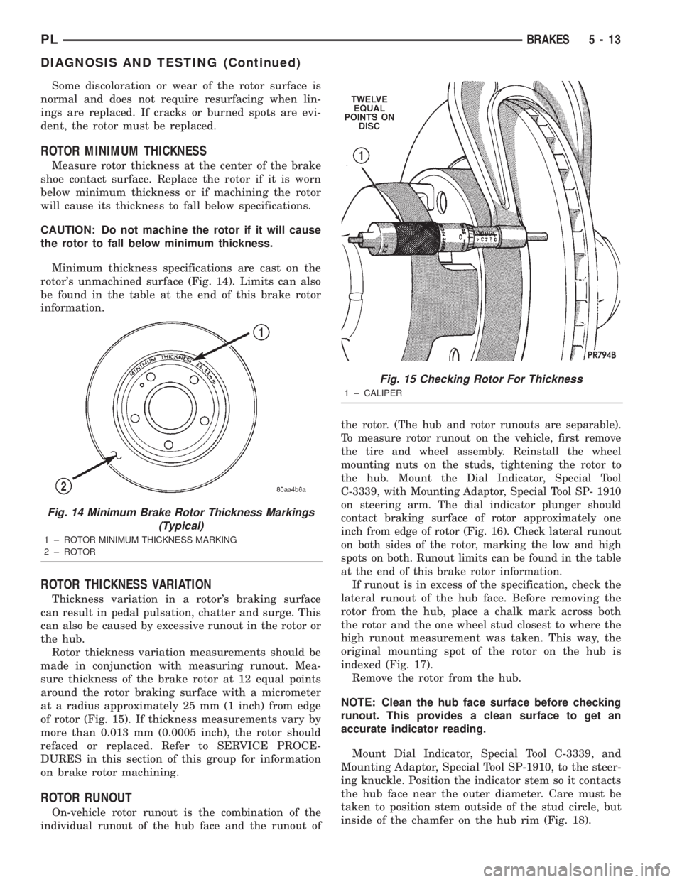
rotor's unmachined surface (Fig. 14). Limits can also
be found in the table at the end of this brake rotor
information.
ROTOR THICKNESS VARIATION
Thickness variation in a rotor's braking surface
can result in pedal pulsation, chatter and surge. This
can also be caused by excessive runout in the rotor or
the hub.
Rotor thickness variation measurements should be
made in conjunction with measuring runout. Mea-
sure thickness of the brake rotor at 12 equal points
around the rotor braking surface with a micrometer
at a radius approximately 25 mm (1 inch) from edge
of rotor (Fig. 15). If thickness measurements vary by
more than 0.013 mm (0.0005 inch), the rotor should
refaced or replaced. Refer to SERVICE PROCE-
DURES in this section of this group for information
on brake rotor machining.
ROTOR RUNOUT
On-vehicle rotor runout is the combination of the
individual runout of the hub face and the runout ofthe rotor. (The hub and rotor runouts are separable).
To measure rotor runout on the vehicle, first remove
the tire and wheel assembly. Reinstall the wheel
mounting nuts on the studs, tightening the rotor to
the hub. Mount the Dial Indicator, Special Tool
C-3339, with Mounting Adaptor, Special Tool SP- 1910
on steering arm. The dial indicator plunger should
contact braking surface of rotor approximately one
inch from edge of rotor (Fig. 16). Check lateral runout
on both sides of the rotor, marking the low and high
spots on both. Runout limits can be found in the table
at the end of this brake rotor information.
If runout is in excess of the specification, check the
lateral runout of the hub face. Before removing the
rotor from the hub, place a chalk mark across both
the rotor and the one wheel stud closest to where the
high runout measurement was taken. This way, the
original mounting spot of the rotor on the hub is
indexed (Fig. 17).
Remove the rotor from the hub.
NOTE: Clean the hub face surface before checking
runout. This provides a clean surface to get an
accurate indicator reading.
Mount Dial Indicator, Special Tool C-3339, and
Mounting Adaptor, Special Tool SP-1910, to the steer-
ing knuckle. Position the indicator stem so it contacts
the hub face near the outer diameter. Care must be
taken to position stem outside of the stud circle, but
inside of the chamfer on the hub rim (Fig. 18).
Fig. 14 Minimum Brake Rotor Thickness Markings
(Typical)
1 ± ROTOR MINIMUM THICKNESS MARKING
2 ± ROTOR
Fig. 15 Checking Rotor For Thickness
1 ± CALIPER
PLBRAKES 5 - 13
DIAGNOSIS AND TESTING (Continued)
Page 94 of 1285
BRAKE ROTOR LIMITS
Braking Rotor Rotor ThicknessMinimum
Rotor
ThicknessRotor
Thickness
VariationRotor
Runout*Rotor Micro
Finish
Front Rotor21.87±22.13 mm
0.861-0.871 in.20.4 mm
0.803 in.0.013 mm
0.0005 in.0.13 mm
0.005 in.15-80 RMS
Rear Rotor8.75±9.25 mm
0.344 -0.364 in.7.25 mm
0.285 in.0.013 mm
0.0005 in.0.13 mm
0.005 in.15-80 RMS
* TIR Total Indicator Reading (Measured On Vehicle)
BRAKE DRUM
With the drum off the vehicle, measure the drum
for diameter variation (oval shape). The diameter
variation of the drum braking surface must not
exceed either 0.0635 mm (0.0025 inch) in 30É or
0.0889 mm (0.0035 inch) in 360É.
Measure brake drum runout. Brake drum runout
should be checked with the drum mounted on a
brake lathe. Brake drum runout should not exceed
0.1524 mm (0.006 inch).
If either of these measurements are not within
specification, reface or replace the drum. Refer to
BRAKE DRUM MACHINING in the SERVICE PRO-
CEDURES section of this service manual group for
refacing procedures.
Always replace the drum if machining will cause
the diameter to exceed drum maximum diameter. All
brake drums are marked with the maximum allow-
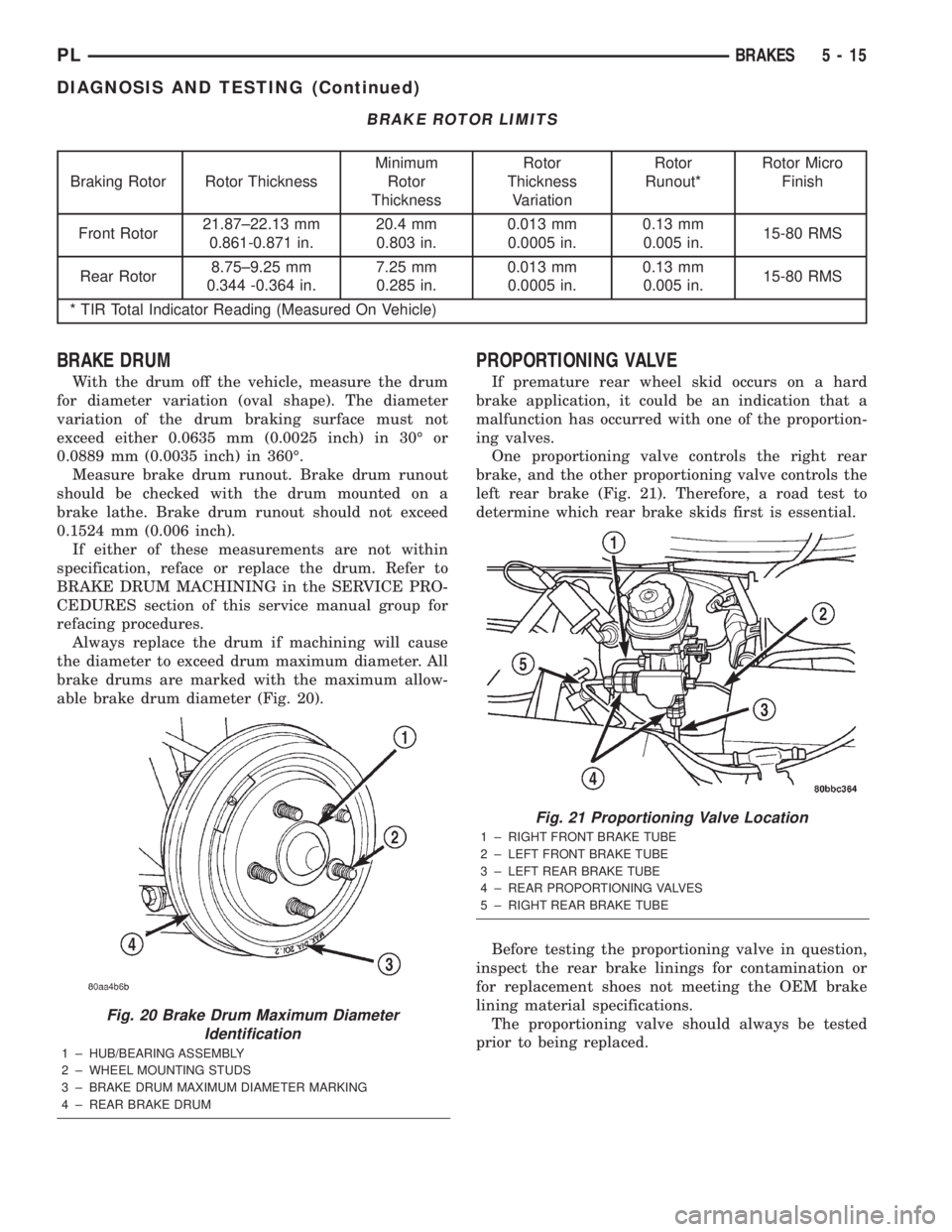
able brake drum diameter (Fig. 20).
PROPORTIONING VALVE
If premature rear wheel skid occurs on a hard
brake application, it could be an indication that a
malfunction has occurred with one of the proportion-
ing valves.
One proportioning valve controls the right rear
brake, and the other proportioning valve controls the
left rear brake (Fig. 21). Therefore, a road test to
determine which rear brake skids first is essential.
Before testing the proportioning valve in question,
inspect the rear brake linings for contamination or
for replacement shoes not meeting the OEM brake
lining material specifications.
The proportioning valve should always be tested
prior to being replaced.
Fig. 20 Brake Drum Maximum Diameter
Identification
1 ± HUB/BEARING ASSEMBLY
2 ± WHEEL MOUNTING STUDS
3 ± BRAKE DRUM MAXIMUM DIAMETER MARKING
4 ± REAR BRAKE DRUM
Fig. 21 Proportioning Valve Location
1 ± RIGHT FRONT BRAKE TUBE
2 ± LEFT FRONT BRAKE TUBE
3 ± LEFT REAR BRAKE TUBE
4 ± REAR PROPORTIONING VALVES
5 ± RIGHT REAR BRAKE TUBE
PLBRAKES 5 - 15
DIAGNOSIS AND TESTING (Continued)
Page 100 of 1285
(5) Place the gauge (From A) over the end of the
brake tube. Adjust the tube height in the tool's jaws
until the end of the tube contacts the recessed notch
in the gauge that matches the tubing size. Squeeze
the handles of the flaring tool, locking the tubing in
place. Remove the gauge.
(6) Place the 3/16 inch plug gauge (A) down into
the end of the tube. Tighten the flaring handle, push-
ing the gauge into the tube until the gauge contacts
the vertical posts of the tool.
(7) Release the flaring handle and remove the plug
gauge from the partially flared tube.
(8) Tighten the flaring handle down once more
until the tools flaring tip has firmly seated the tube
to the vertical posts, thus completing the flare.
CAUTION: When inspecting the flare, make sure no
tubing nygal coating has been involved in the flare.
(9) Remove the flared tube from the flaring tool
and inspect the flare to make sure it is uniform.
BRAKE ROTOR MACHINING
NOTE: Refacing the rotor is not required each time
the brake pads are replaced, only when the need is
foreseen.
Any servicing of the rotor requires extreme care to
maintain the rotor within service tolerances to
ensure proper brake action.
If the rotor surface is deeply scored or warped, or
there is a complaint of brake roughness or brake
pedal pulsation, the rotor should be refaced using a
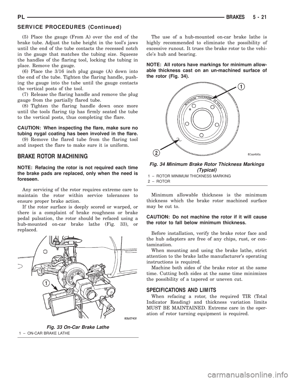
hub-mounted on-car brake lathe (Fig. 33), or
replaced.The use of a hub-mounted on-car brake lathe is
highly recommended to eliminate the possibility of
excessive runout. It trues the brake rotor to the vehi-
cle's hub and bearing.
NOTE: All rotors have markings for minimum allow-
able thickness cast on an un-machined surface of
the rotor (Fig. 34).
Minimum allowable thickness is the minimum
thickness which the brake rotor machined surface
may be cut to.
CAUTION: Do not machine the rotor if it will cause
the rotor to fall below minimum thickness.
Before installation, verify the brake rotor face and
the hub adapters are free of any chips, rust, or con-
tamination.
When mounting and using the brake lathe, strict
attention to the brake lathe manufacturer's operating
instructions is required.
Machine both sides of the brake rotor at the same
time. Cutting both sides at the same time minimizes
the possibility of a tapered or uneven cut.
SPECIFICATIONS AND LIMITS
When refacing a rotor, the required TIR (Total
Indicator Reading) and thickness variation limits
MUST BE MAINTAINED. Extreme care in the oper-
ation of rotor turning equipment is required.
Fig. 33 On-Car Brake Lathe
1 ± ON-CAR BRAKE LATHE
Fig. 34 Minimum Brake Rotor Thickness Markings
(Typical)
1 ± ROTOR MINIMUM THICKNESS MARKING
2 ± ROTOR
PLBRAKES 5 - 21
SERVICE PROCEDURES (Continued)
Page 101 of 1285
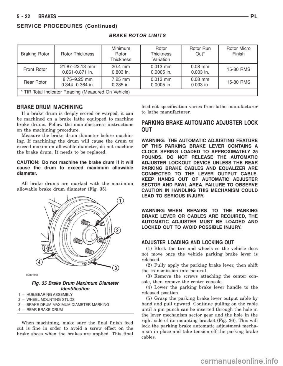
BRAKE ROTOR LIMITS
Braking Rotor Rotor ThicknessMinimum
Rotor
ThicknessRotor
Thickness
VariationRotor Run
Out*Rotor Micro
Finish
Front Rotor21.87±22.13 mm
0.861-0.871 in.20.4 mm
0.803 in.0.013 mm
0.0005 in.0.08 mm
0.003 in.15-80 RMS
Rear Rotor8.75±9.25 mm
0.344 -0.364 in.7.25 mm
0.285 in.0.013 mm
0.0005 in.0.08 mm
0.003 in.15-80 RMS
* TIR Total Indicator Reading (Measured On Vehicle)
BRAKE DRUM MACHINING
If a brake drum is deeply scored or warped, it can
be machined on a brake lathe equipped to machine
brake drums. Follow the manufacturers instructions
on the machining procedure.
Measure the brake drum diameter before machin-
ing. If machining the drum will cause the drum to
exceed maximum allowable diameter, do not machine
the brake drum. It needs to be replaced.
CAUTION: Do not machine the brake drum if it will
cause the drum to exceed maximum allowable
diameter.
All brake drums are marked with the maximum
allowable brake drum diameter (Fig. 35).
When machining, make sure the final finish feed
cut is fine in order to avoid a screw effect on the
brake shoes when the brakes are applied. This finalfeed cut specification varies from lathe manufacturer
to lathe manufacturer.
PARKING BRAKE AUTOMATIC ADJUSTER LOCK
OUT
WARNING: THE AUTOMATIC ADJUSTING FEATURE
OF THIS PARKING BRAKE LEVER CONTAINS A
CLOCK SPRING LOADED TO APPROXIMATELY 25
POUNDS. DO NOT RELEASE THE AUTOMATIC
ADJUSTER LOCKOUT DEVICE UNLESS THE REAR
PARKING BRAKE CABLES AND EQUALIZER ARE
CONNECTED TO THE LEVER OUTPUT CABLE.
KEEP HANDS OUT OF AUTOMATIC ADJUSTER
SECTOR AND PAWL AREA. FAILURE TO OBSERVE
CAUTION IN HANDLING THIS MECHANISM COULD
LEAD TO SERIOUS INJURY.
WARNING: WHEN REPAIRS TO THE PARKING
BRAKE LEVER OR CABLES ARE REQUIRED, THE
AUTOMATIC ADJUSTER MUST BE LOADED AND
LOCKED OUT TO AVOID POSSIBLE INJURY.
ADJUSTER LOADING AND LOCKING OUT
(1) Block the tire and wheels so the vehicle does
not move once the vehicle parking brake lever is
released.
(2) Fully apply the parking brake lever, then shift
the transmission into neutral.
(3) Remove the screws attaching the center con-
sole, then remove the center console.
(4) Lower the parking brake lever handle to the
released position.
(5) Grasp the parking brake lever output cable by
hand and pull upward. Continue pulling on the cable
until a pin punch can be inserted through the hole in
the lever mechanism sector gear and the hole in the
right side of its mounting bracket (Fig. 36). This will
lock the parking brake automatic adjustment mecha-
nism in place and take tension off the parking brake
cables.
Fig. 35 Brake Drum Maximum Diameter
Identification
1 ± HUB/BEARING ASSEMBLY
2 ± WHEEL MOUNTING STUDS
3 ± BRAKE DRUM MAXIMUM DIAMETER MARKING
4 ± REAR BRAKE DRUM
5 - 22 BRAKESPL
SERVICE PROCEDURES (Continued)
Page 205 of 1285
(3) Install power steering pump and A/C compres-
sor drive belt.
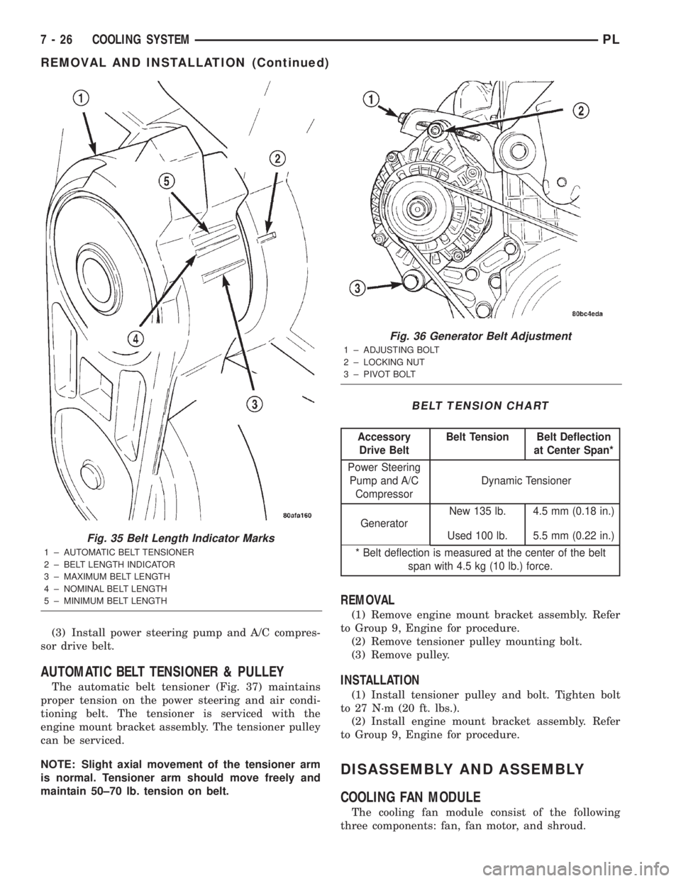
AUTOMATIC BELT TENSIONER & PULLEY
The automatic belt tensioner (Fig. 37) maintains
proper tension on the power steering and air condi-
tioning belt. The tensioner is serviced with the
engine mount bracket assembly. The tensioner pulley
can be serviced.
NOTE: Slight axial movement of the tensioner arm
is normal. Tensioner arm should move freely and
maintain 50±70 lb. tension on belt.
REMOVAL
(1) Remove engine mount bracket assembly. Refer
to Group 9, Engine for procedure.
(2) Remove tensioner pulley mounting bolt.
(3) Remove pulley.
INSTALLATION
(1) Install tensioner pulley and bolt. Tighten bolt
to 27 N´m (20 ft. lbs.).
(2) Install engine mount bracket assembly. Refer
to Group 9, Engine for procedure.
DISASSEMBLY AND ASSEMBLY
COOLING FAN MODULE
The cooling fan module consist of the following
three components: fan, fan motor, and shroud.
Fig. 35 Belt Length Indicator Marks
1 ± AUTOMATIC BELT TENSIONER
2 ± BELT LENGTH INDICATOR
3 ± MAXIMUM BELT LENGTH
4 ± NOMINAL BELT LENGTH
5 ± MINIMUM BELT LENGTH
Fig. 36 Generator Belt Adjustment
1 ± ADJUSTING BOLT
2 ± LOCKING NUT
3 ± PIVOT BOLT
BELT TENSION CHART
Accessory
Drive BeltBelt Tension Belt Deflection
at Center Span*
Power Steering
Pump and A/C
CompressorDynamic Tensioner
GeneratorNew 135 lb. 4.5 mm (0.18 in.)
Used 100 lb. 5.5 mm (0.22 in.)
* Belt deflection is measured at the center of the belt
span with 4.5 kg (10 lb.) force.
7 - 26 COOLING SYSTEMPL
REMOVAL AND INSTALLATION (Continued)
Page 210 of 1285
BATTERY
TABLE OF CONTENTS
page page
GENERAL INFORMATION
INTRODUCTION..........................1
DESCRIPTION AND OPERATION
BATTERY IGNITION OFF DRAW (IOD).........2
CHARGING TIME REQUIRED................2
DIAGNOSIS AND TESTING
BATTERY BUILT-IN TEST INDICATOR.........3
BATTERY IGNITION OFF DRAW (IOD).........4
BATTERY LOAD TEST......................6
BATTERY OPEN CIRCUIT VOLTAGE...........7
SERVICE PROCEDURES
BATTERY CHARGING......................7CHARGING COMPLETELY DISCHARGED
BATTERY..............................8
VISUAL INSPECTION......................9
REMOVAL AND INSTALLATION
BATTERY...............................10
BATTERY THERMOWRAP..................10
BATTERY TRAY..........................11
SPECIFICATIONS
BATTERY SPECIFICATIONS................11
TORQUE...............................11
GENERAL INFORMATION
INTRODUCTION
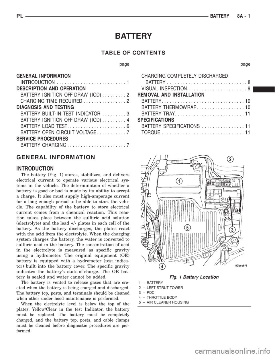
The battery (Fig. 1) stores, stabilizes, and delivers
electrical current to operate various electrical sys-
tems in the vehicle. The determination of whether a
battery is good or bad is made by its ability to accept
a charge. It also must supply high-amperage current
for a long enough period to be able to start the vehi-
cle. The capability of the battery to store electrical
current comes from a chemical reaction. This reac-
tion takes place between the sulfuric acid solution
(electrolyte) and the lead +/- plates in each cell of the
battery. As the battery discharges, the plates react
with the acid from the electrolyte. When the charging
system charges the battery, the water is converted to
sulfuric acid in the battery. The concentration of acid
in the electrolyte is measured as specific gravity
using a hydrometer. The original equipment (OE)
battery is equipped with a hydrometer (test indica-
tor) built into the battery cover. The specific gravity
indicates the battery's state-of-charge. The OE bat-
tery is sealed and water cannot be added.
The battery is vented to release gases that are cre-
ated when the battery is being charged and discharged.
The battery top, posts, and terminals should be cleaned
when other under hood maintenance is performed.
When the electrolyte level is below the top of the
plates, Yellow/Clear in the test Indicator, the battery
must be replaced. The battery must be completely
charged, and the battery top, posts, and cable clamps
must be cleaned before diagnostic procedures are per-
formed.
Fig. 1 Battery Location
1 ± BATTERY
2 ± LEFT STRUT TOWER
3 ± PDC
4 ± THROTTLE BODY
5 ± AIR CLEANER HOUSING
PLBATTERY 8A - 1