Page 1077 of 1285

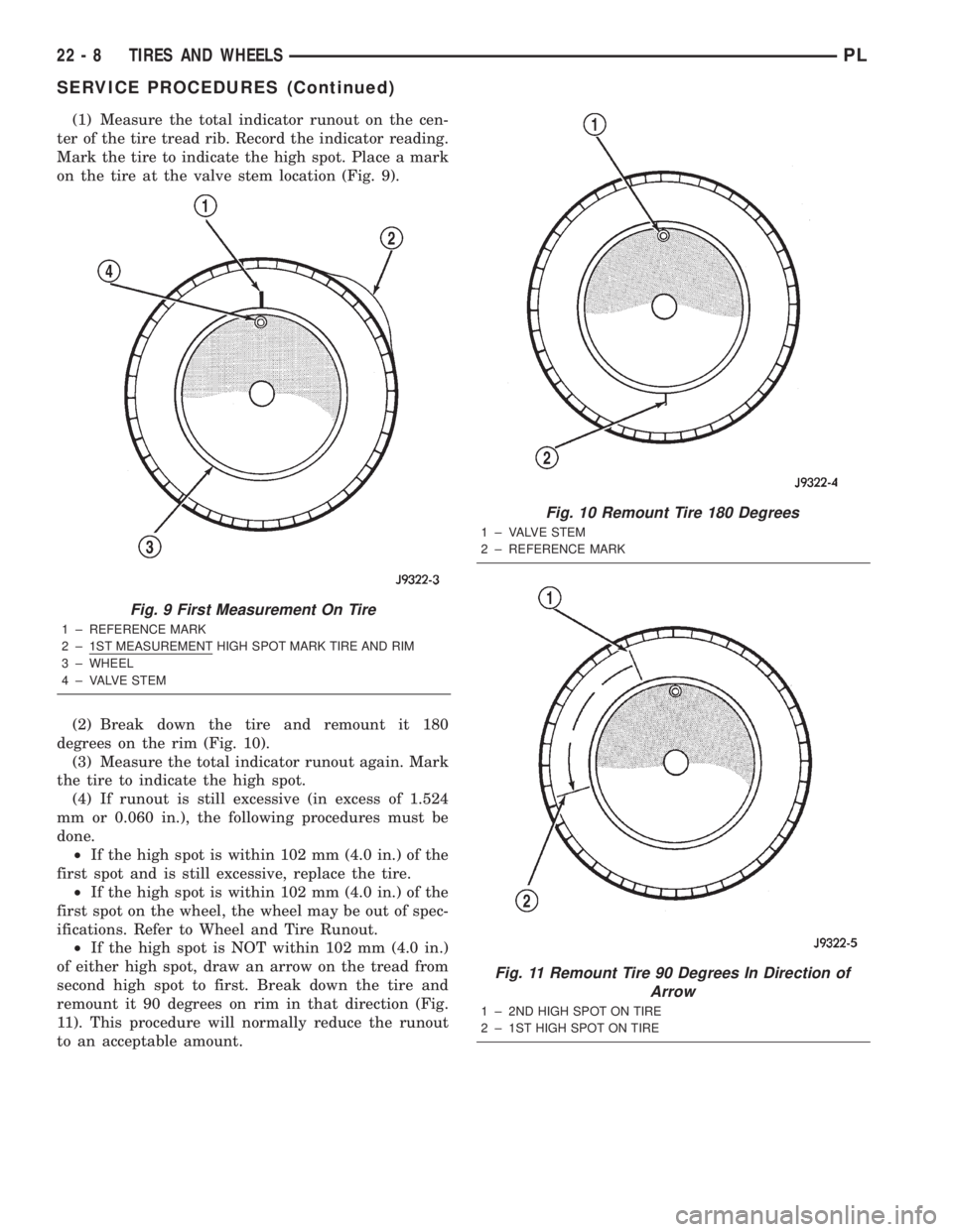
(1) Measure the total indicator runout on the cen-
ter of the tire tread rib. Record the indicator reading.
Mark the tire to indicate the high spot. Place a mark
on the tire at the valve stem location (Fig. 9).
(2) Break down the tire and remount it 180
degrees on the rim (Fig. 10).
(3) Measure the total indicator runout again. Mark
the tire to indicate the high spot.
(4) If runout is still excessive (in excess of 1.524
mm or 0.060 in.), the following procedures must be
done.
²If the high spot is within 102 mm (4.0 in.) of the
first spot and is still excessive, replace the tire.
²If the high spot is within 102 mm (4.0 in.) of the
first spot on the wheel, the wheel may be out of spec-
ifications. Refer to Wheel and Tire Runout.
²If the high spot is NOT within 102 mm (4.0 in.)
of either high spot, draw an arrow on the tread from
second high spot to first. Break down the tire and
remount it 90 degrees on rim in that direction (Fig.
11). This procedure will normally reduce the runout
to an acceptable amount.
Fig. 9 First Measurement On Tire
1 ± REFERENCE MARK
2 ± 1ST MEASUREMENT HIGH SPOT MARK TIRE AND RIM
3 ± WHEEL
4 ± VALVE STEM
Fig. 10 Remount Tire 180 Degrees
1 ± VALVE STEM
2 ± REFERENCE MARK
Fig. 11 Remount Tire 90 Degrees In Direction of
Arrow
1 ± 2ND HIGH SPOT ON TIRE
2 ± 1ST HIGH SPOT ON TIRE
22 - 8 TIRES AND WHEELSPL
SERVICE PROCEDURES (Continued)
Page 1082 of 1285

METHOD 2 (RELOCATE TIRE ON WHEEL)
Rotating tire on wheel is particularly effective
when there is run out in both tire and wheel.
Remove tire from wheel and remount wheel on hub
in former position.
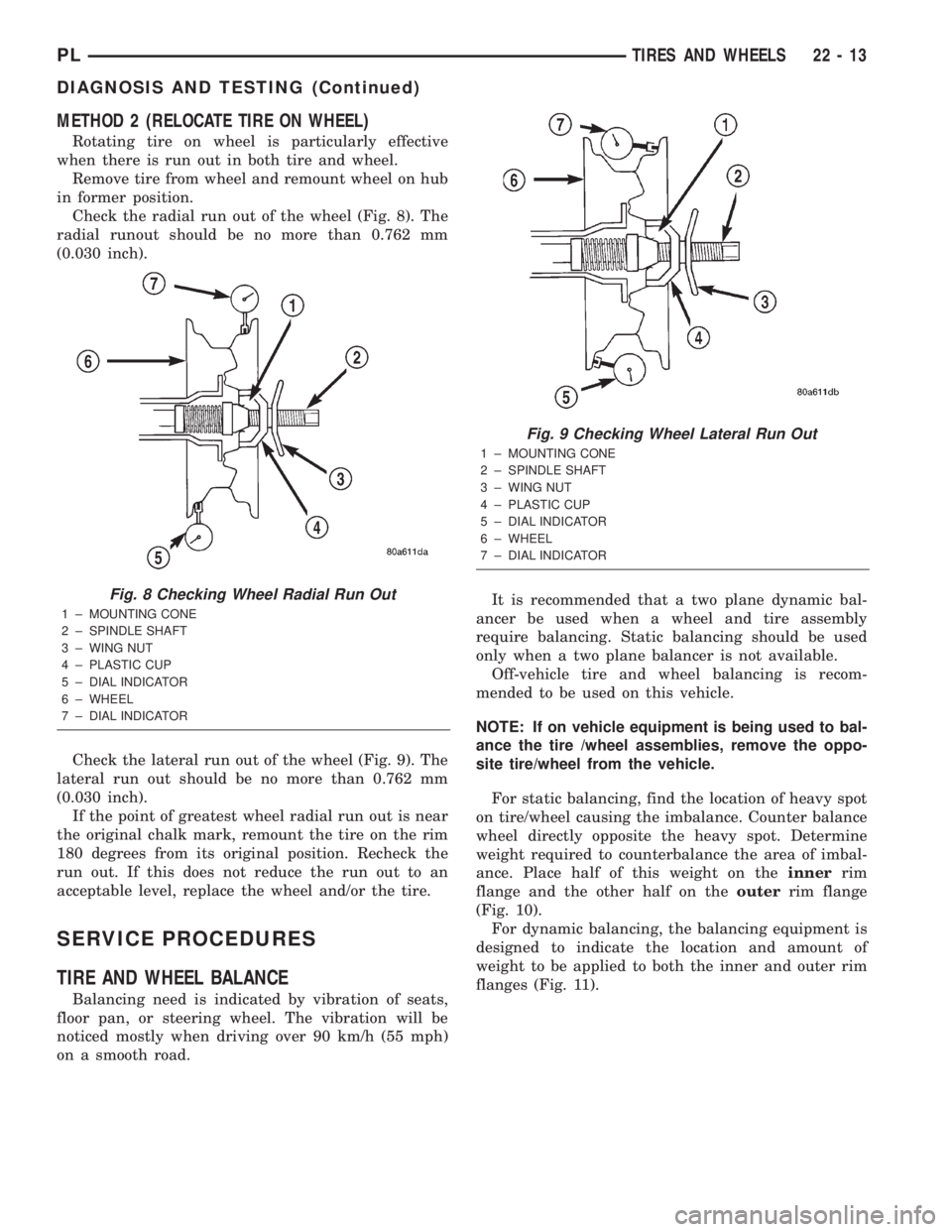
Check the radial run out of the wheel (Fig. 8). The
radial runout should be no more than 0.762 mm
(0.030 inch).
Check the lateral run out of the wheel (Fig. 9). The
lateral run out should be no more than 0.762 mm
(0.030 inch).
If the point of greatest wheel radial run out is near
the original chalk mark, remount the tire on the rim
180 degrees from its original position. Recheck the
run out. If this does not reduce the run out to an
acceptable level, replace the wheel and/or the tire.
SERVICE PROCEDURES
TIRE AND WHEEL BALANCE
Balancing need is indicated by vibration of seats,
floor pan, or steering wheel. The vibration will be
noticed mostly when driving over 90 km/h (55 mph)
on a smooth road.It is recommended that a two plane dynamic bal-
ancer be used when a wheel and tire assembly
require balancing. Static balancing should be used
only when a two plane balancer is not available.
Off-vehicle tire and wheel balancing is recom-
mended to be used on this vehicle.
NOTE: If on vehicle equipment is being used to bal-
ance the tire /wheel assemblies, remove the oppo-
site tire/wheel from the vehicle.
For static balancing, find the location of heavy spot
on tire/wheel causing the imbalance. Counter balance
wheel directly opposite the heavy spot. Determine
weight required to counterbalance the area of imbal-
ance. Place half of this weight on theinnerrim
flange and the other half on theouterrim flange
(Fig. 10).
For dynamic balancing, the balancing equipment is
designed to indicate the location and amount of
weight to be applied to both the inner and outer rim
flanges (Fig. 11).
Fig. 8 Checking Wheel Radial Run Out
1 ± MOUNTING CONE
2 ± SPINDLE SHAFT
3 ± WING NUT
4 ± PLASTIC CUP
5 ± DIAL INDICATOR
6 ± WHEEL
7 ± DIAL INDICATOR
Fig. 9 Checking Wheel Lateral Run Out
1 ± MOUNTING CONE
2 ± SPINDLE SHAFT
3 ± WING NUT
4 ± PLASTIC CUP
5 ± DIAL INDICATOR
6 ± WHEEL
7 ± DIAL INDICATOR
PLTIRES AND WHEELS 22 - 13
DIAGNOSIS AND TESTING (Continued)
Page 1101 of 1285

(M) Check Engine Lamp (MIL) will illuminate during engine operation if this Diagnostic Trouble Code was recorded.
P1684 The battery has been disconnected within the last 50
starts.
P1685 Skim Invalid Key The engine controler has received an invalid key from
the SKIM.
P1686 No SKIM BUS Messages Received No CCD/J1850 messages received from the Smart Key
Immobilizer Module (SKIM).
P1687 No MIC BUS Message No CCD/J1850 messages received from the Mechanical
Instrument Cluster (MIC) module.
P1693 DTC Detected in Companion
ModuleA fault has been generated in the companion engine
control module.
P1694 Fault In Companion Module No CCD/J1850 messages received from the powertrain
control module-Aisin transmission.
P1695 No CCD/J1850 Message From
Body Control ModuleNo CCD/J1850 messages received from the body
control module.
P1696 (M) PCM Failure EEPROM Write
DeniedUnsuccessful attempt to write to an EEPROM location
by the control module.
P1697 (M) PCM Failure SRI Mile Not Stored Unsuccessful attempt to update Service Reminder
Indicator (SRI or EMR) mileage in the control module
EEPROM.
P1698 (M) No CCD/J1850 Message From TCM No CCD/J1850 messages received from the electronic
transmission control module (EATX) or the Aisin
transmission controller.
P1719 Skip Shift Solenoid Circuit An open or shorted condition detected in the
transmission 2-3 gear lock-out solenoid control circuit.
P1756 GOV Press Not Equal to Target @
15-20 PSIThe requested pressure and the actual pressure are not
within a tolerance band for the Governor Control
System which is used to regulate governor pressure to
control shifts for 1st, 2nd, and 3rd gear. (Mid Pressure
Malfunction)
P1757 GOV Press Not Equal to Target @
15-20 PSIThe requested pressure and the actual pressure are not
within a tolerance band for the Governor Control
System which is used to regulate governor pressure to
control shifts for 1st, 2nd, and 3rd gear (Zero Pressure
Malfunction)
P1762 Gov Press Sen Offset Volts Too Lo
or HighThe Governor Pressure Sensor input is greater than a
calibration limit or is less than a calibration limit for 3
consecutive park/neutral calibrations.
P1763 Governor Pressure Sensor Volts
To o H iThe Governor Pressure Sensor input is above an
acceptable voltage level.
P1764 Governor Pressure Sensor Volts
Too LowThe Governor Pressure Sensor input is below an
acceptable voltage level.
P1765 Trans 12 Volt Supply Relay CTRL
CircuitAn open or shorted condition is detected in the
Transmission Relay control circuit. This relay supplies
power to the TCC>
P1899 (M) P/N Switch Stuck in Park or in Gear Incorrect input state detected for the Park/Neutral
switch.
25 - 14 EMISSION CONTROL SYSTEMSPL
DESCRIPTION AND OPERATION (Continued)