2000 DODGE NEON service indicator
[x] Cancel search: service indicatorPage 375 of 1285
memory to determine whether a valid key is in the
ignition lock cylinder.
The Sentry Key transponder cannot be repaired
and, if faulty or damaged, it must be replaced.
SENTRY KEY IMMOBILIZER SYSTEM
INDICATOR LAMP
The Sentry Key Immobilizer System (SKIS) uses
the Vehicle Theft Security System (VTSS) indicator
LED to give an indication when the SKIS is faulty or
when the vehicle has been immobilized due to the
use of an invalid ignition key. The LED is controlled
by the instrument cluster circuitry based upon mes-
sages received from the Sentry Key Immobilizer
Module (SKIM) through the Body Control Module
(BCM) on the Programmable Communication Inter-
face (PCI) bus.
The SKIM sends messages to the instrument clus-
ter, via the BCM, to turn the LED on for about three
seconds when the ignition switch is turned to the ON
position as a bulb test. After completion of the bulb
test, the SKIM sends PCI bus messages to keep the
LED off for a duration of about one second. Then the
SKIM sends messages to the instrument cluster cir-
cuitry to turn the LED on or off based upon the
results of the SKIS self-tests. If the VTSS indicator
LED comes on and stays on after the bulb test, it
indicates that the SKIM has detected a system mal-
function and/or that the SKIS has become inopera-
tive. If the SKIM detects an invalid key when the
ignition switch is turned to the ON position, it sends
messages to the instrument cluster to flash the VTSS
indicator LED.
The SKIM can also send messages to the instru-
ment cluster to flash the LED and to generate a sin-
gle audible chime tone. These functions serve as an
indication to the customer that the SKIS has been
placed in its ªCustomer Learnº programming mode.
See Sentry Key Immobilizer System Transponder
Programming in this group for more information on
the ªCustomer Learnº programming mode.
The VTSS indicator LED uses a replaceable Light
Emitting Diode (LED) on the instrument cluster elec-
tronic circuit board. Refer to Group 8E - Instrument
Panel Systems for Cluster Lamp Removal and Instal-
lation. If the VTSS indicator LED comes on and
stays on after the bulb test function, diagnosis of the
SKIS should be performed with a DRB IIItscan tool
and the proper Body Diagnostic Procedures Manual.
TRIGGERING THE VTSS
After the VTSS is armed, any of the following will
trigger the system:
²Opening any door.
²Opening the hood.
²Removing the trunk lock cylinder.²Turning the ignition to the RUN/START position
with an invalid Sentry Key.
NOTE: The ignition switch can be turned to the
accessory position without triggering the alarm sys-
tem.
DIAGNOSIS AND TESTING
SENTRY KEY IMMOBILIZER SYSTEM
WARNING: ON VEHICLES EQUIPPED WITH AIR-
BAGS, REFER TO GROUP 8M - PASSIVE
RESTRAINT SYSTEMS BEFORE ATTEMPTING ANY
STEERING WHEEL, STEERING COLUMN, OR
INSTRUMENT PANEL COMPONENT DIAGNOSIS OR
SERVICE. FAILURE TO TAKE THE PROPER PRE-
CAUTIONS COULD RESULT IN ACCIDENTAL AIR-
BAG DEPLOYMENT AND POSSIBLE PERSONAL
INJURY.
NOTE: The following tests may not prove conclu-
sive in the diagnosis of this system. The most reli-
able, efficient, and accurate means to diagnose the
Sentry Key Immobilizer System (SKIS) involves the
use of a DRB lllTscan tool and the proper Body
Diagnostic Procedures Manual.
The Sentry Key Immobilizer System (SKIS) and
the Programmable Communication Interface (PCI)
bus network should be diagnosed using a DRB lllt
scan tool. The DRB IIItwill allow confirmation that
the PCI bus is functional, that the Sentry Key Immo-
bilizer Module (SKIM) is placing the proper messages
on the PCI bus, and that the Powertrain Control
Module (PCM) and the instrument cluster are receiv-
ing the PCI bus messages. Refer to the proper Body
Diagnostic Procedures Manual. Refer to Group
8W-Wiring Diagrams for complete circuit descriptions
and diagrams.
(1) Check the fuses in the fuse block. If OK, go to
Step 2. If not OK, repair the shorted circuit or com-
ponent as required and replace the faulty fuse.
(2) Disconnect and isolate the battery negative
cable (Fig. 3). Unplug the wire harness connector at
the SKIM. Check for continuity between the ground
circuit cavity of the SKIM wire harness connector
and a good ground. There should be continuity. If
OK, go to Step 3. If not OK, repair the open circuit to
ground as required.
(3) Connect the battery negative cable. Check for
battery voltage at the fused B(+) circuit cavity of the
SKIM wire harness connector. If OK, go to Step 4. If
not OK, repair the open circuit to the fuse in the fuse
block as required.
8Q - 4 VEHICLE THEFT/SECURITY SYSTEMPL
DESCRIPTION AND OPERATION (Continued)
Page 377 of 1285
(3) After the ignition switch has been in the ON
position for about three seconds, but no more than
fifteen seconds, cycle the ignition switch back to the
OFF position. Replace the first valid Sentry Key in
the ignition lock cylinder with the second valid Sen-
try Key and turn the ignition switch back to the ON
position. Both operations must be performed within
15 seconds.
(4) About ten seconds after the completion of Step
3, the VTSS indicator LED will start to flash and a
single audible chime tone will sound to indicate that
the system has entered the ªCustomer Learnº pro-
gramming mode.
(5) Within about fifty seconds of entering the ªCus-
tomer Learnº programming mode, turn the ignition
switch to the OFF position, replace the valid Sentry
Key with a blank Sentry Key transponder, and turn
the ignition switch back to the ON position.
(6) About ten seconds after the completion of Step
5, a single audible chime tone will sound and the
VTSS indicator LED will stop flashing and stay on
solid for about three seconds to indicate that the
blank Sentry Key transponder has been successfully
programmed. The SKIS will immediately return to
normal system operation following exit from the
ªCustomer Learnº programming mode.
(7) Go back to Step 2 and repeat this process for
each additional Sentry Key transponder blank to be
programmed.
If any of the above steps is not completed in the
proper sequence, or within the allotted time, the
SKIS will automatically exit the ªCustomer Learnº
programming mode. The SKIS will also automatically
exit the ªCustomer Learnº programming mode if it
sees a non-blank Sentry Key transponder when it
should see a blank, if it has already programmed
eight valid Sentry Keys, or if the ignition switch is
turned to the OFF position for more than about fifty
seconds.
PROGRAMMING BLANK SENTRY KEY
TRANSPONDERS WITH A DRB lllTSCAN TOOL
When programming a blank Sentry Key transpon-
der, the key blank must first be cut to match the
ignition lock cylinder. It will also be necessary to
enter the vehicle's four digit PIN code into the DRB
IIItscan tool to enter the Sentry Key Immobilizer
Module's (SKIM's) secured access mode.
NOTE: Once a Sentry Key is programmed to a par-
ticular vehicle, it cannot be transferred to another
vehicle.
Insert the blank key into the ignition and turn it to
the RUN position. Using the DRB IIItscan tool,
select ªTheft Alarm,º then ªSKIM,º then ªMiscella-
neous.º Select ªProgram New Key.º Enter the fourdigit PIN code using the DRB IIIt. When program-
ming is completed, the SKIM will exit secured access
mode and display the status of the key. One of five
different status messages may be displayed as fol-
lows:
²ªProgramming Successfulº is displayed if SKIM
Sentry Key programming succeeds.
²ªLearned Key in Ignitionº is displayed if the key
in the ignition has already been programmed into
that vehicle's SKIM.
²ª8 Keys Already Learned (At The Maximum)
Programming Not Doneº is displayed if eight keys
have already been programmed into the SKIM. In
this case, if a new key needs to be added due to a
lost or defective key, the ªErase All Keysº function
(requires entering secured access mode) has to be
performed. Then the customer is seven keys plus the
new key MUST be reprogrammed into the SKIM.
²ªProgramming Not Attemptedº is displayed after
an ªErase All Keysº function is executed.
²ªProgramming Key Failedº is displayed if fur-
ther diagnosis is required.
²To learn additional keys, turn the ignition OFF,
remove the learned key, and insert the next new
blank key. Turn ignition to the RUN position and re-
enter the secured access mode function and repeat
the ªProgram New Keyº procedure outlined above.
SWITCHING OPERATING MODES/
CONFIGURING A NEW MODULE
To switch operating modes or to configure a new
module, a DRB IIItscan tool must be used.
(1) Hook up the DRB IIItscan tool to the Data
Link Connector (DLC) (Fig. 4).
(2) With the key in the ignition, turn the key to
the RUN position.
(3) After the DRB IIItscan tool initialization, per-
form the following:
(a) Select ªTheft Alarm.º
(b) Select ªVTSS.º
(c) Select ªMiscellaneous.º
(4) Once in the ªMiscellaneousº screen:
(a) If you wish to configure a new module, select
ªConfigure Module.º
(b) If you wish to put the module into customer
usage mode, select ªEnable VTSS.º
(c) If you wish to put the module into dealer lot
mode, select ªDealer Lot.º
8Q - 6 VEHICLE THEFT/SECURITY SYSTEMPL
SERVICE PROCEDURES (Continued)
Page 731 of 1285
ENGINE DIAGNOSIS
TABLE OF CONTENTS
page page
DIAGNOSIS AND TESTING
GENERAL INFORMATION...................8
INTAKE MANIFOLD LEAKAGE DIAGNOSIS......8
CYLINDER COMPRESSION PRESSURE TEST . . . 8
CYLINDER COMBUSTION PRESSURE
LEAKAGE TEST.........................9LASH ADJUSTER (TAPPET) NOISE
DIAGNOSIS............................9
ENGINE OIL LEAK INSPECTION..............9
ENGINE DIAGNOSISÐPERFORMANCE........11
ENGINE DIAGNOSISÐMECHANICAL.........12
DIAGNOSIS AND TESTING
GENERAL INFORMATION
Engine diagnosis is helpful in determining the
causes of malfunctions not detected and remedied by
routine maintenance.
These malfunctions may be classified as either
mechanical (e.g., a strange noise), or performance
(e.g., engine idles rough and stalls).
Refer to the Service DiagnosisÐMechanical Chart
and the Service DiagnosisÐPerformance Chart, for
possible causes and corrections of malfunctions. Refer
to Group 14, Fuel System, for the fuel system diag-
nosis.
Additional tests and diagnostic procedures may be
necessary for specific engine malfunctions that can-
not be isolated with the Service Diagnosis charts.
Information concerning additional tests and diagno-
sis is provided within the following:
²Cylinder Compression Pressure Test
²Cylinder Combustion Pressure Leakage Test
²Engine Cylinder Head Gasket Failure Diagnosis
²Intake Manifold Leakage Diagnosis
INTAKE MANIFOLD LEAKAGE DIAGNOSIS
An intake manifold air leak is characterized by
lower than normal manifold vacuum. Also, one or
more cylinders may not be functioning.
WARNING: USE EXTREME CAUTION WHEN THE
ENGINE IS OPERATING. DO NOT STAND IN A
DIRECT LINE WITH THE FAN. DO NOT PUT YOUR
HANDS NEAR THE PULLEYS, BELTS OR THE FAN.
DO NOT WEAR LOOSE CLOTHING.
(1) Start the engine.
(2) Spray a small stream of water (Spray Bottle) at
the suspected leak area.
(3) If engine RPM'S change, the area of the sus-
pected leak has been found.
(4) Repair as required.
CYLINDER COMPRESSION PRESSURE TEST
The results of a cylinder compression pressure test
can be utilized to diagnose several engine malfunc-
tions.
Ensure the battery is completely charged and the
engine starter motor is in good operating condition.
Otherwise the indicated compression pressures may
not be valid for diagnosis purposes.
(1) Check engine oil level and add oil if necessary.
(2) Drive the vehicle until engine reaches normal
operating temperature. Select a route free from traf-
fic and other forms of congestion, observe all traffic
laws, and accelerate through the gears several times
briskly.
(3) Remove all spark plugs from engine. As spark
plugs are being removed, check electrodes for abnor-
mal firing indicators fouled, hot, oily, etc. Record cyl-
inder number of spark plug for future reference.
(4) Disconnect coil wire from distributor and
secure to good ground to prevent a spark from start-
ing a fire (Conventional Ignition System). For Direct
Ignition System DIS disconnect the coil connector.
(5) Be sure throttle blade is fully open during the
compression check.
(6) Insert compression gage adaptor into the #1
spark plug hole in cylinder head. Crank engine until
maximum pressure is reached on gage. Record this
pressure as #1 cylinder pressure.
(7) Repeat the previous step for all remaining cyl-
inders.
(8) Compression should not be less than (689 kPa)
100 psi and not vary more than 25 percent from cyl-
inder to cylinder.
(9) If one or more cylinders have abnormally low
compression pressures, repeat the compression test.
(10) If the same cylinder or cylinders repeat an
abnormally low reading on the second compression
test, it could indicate the existence of a problem in
the cylinder in question.The recommended com-
pression pressures are to be used only as a
guide to diagnosing engine problems. An engine
9 - 8 ENGINEPL
Page 743 of 1285
CRANKSHAFT END PLAY
DIAL INDICATOR METHOD
(1) Mount a dial indicator to front of engine, locat-
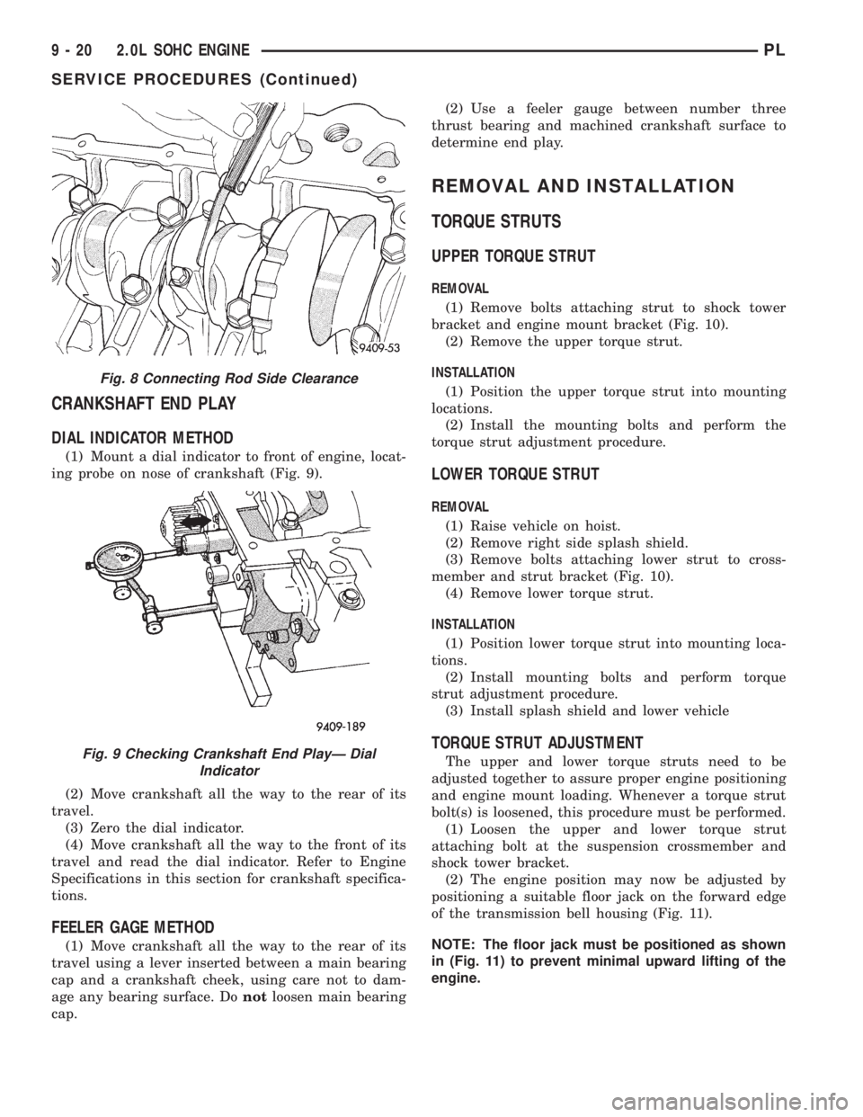
ing probe on nose of crankshaft (Fig. 9).
(2) Move crankshaft all the way to the rear of its
travel.
(3) Zero the dial indicator.
(4) Move crankshaft all the way to the front of its
travel and read the dial indicator. Refer to Engine
Specifications in this section for crankshaft specifica-
tions.
FEELER GAGE METHOD
(1) Move crankshaft all the way to the rear of its
travel using a lever inserted between a main bearing
cap and a crankshaft cheek, using care not to dam-
age any bearing surface. Donotloosen main bearing
cap.(2) Use a feeler gauge between number three
thrust bearing and machined crankshaft surface to
determine end play.
REMOVAL AND INSTALLATION
TORQUE STRUTS
UPPER TORQUE STRUT
REMOVAL
(1) Remove bolts attaching strut to shock tower
bracket and engine mount bracket (Fig. 10).
(2) Remove the upper torque strut.
INSTALLATION
(1) Position the upper torque strut into mounting
locations.
(2) Install the mounting bolts and perform the
torque strut adjustment procedure.
LOWER TORQUE STRUT
REMOVAL
(1) Raise vehicle on hoist.
(2) Remove right side splash shield.
(3) Remove bolts attaching lower strut to cross-
member and strut bracket (Fig. 10).
(4) Remove lower torque strut.
INSTALLATION
(1) Position lower torque strut into mounting loca-
tions.
(2) Install mounting bolts and perform torque
strut adjustment procedure.
(3) Install splash shield and lower vehicle
TORQUE STRUT ADJUSTMENT
The upper and lower torque struts need to be
adjusted together to assure proper engine positioning
and engine mount loading. Whenever a torque strut
bolt(s) is loosened, this procedure must be performed.
(1) Loosen the upper and lower torque strut
attaching bolt at the suspension crossmember and
shock tower bracket.
(2) The engine position may now be adjusted by
positioning a suitable floor jack on the forward edge
of the transmission bell housing (Fig. 11).
NOTE: The floor jack must be positioned as shown
in (Fig. 11) to prevent minimal upward lifting of the
engine.
Fig. 8 Connecting Rod Side Clearance
Fig. 9 Checking Crankshaft End PlayÐ Dial
Indicator
9 - 20 2.0L SOHC ENGINEPL
SERVICE PROCEDURES (Continued)
Page 862 of 1285
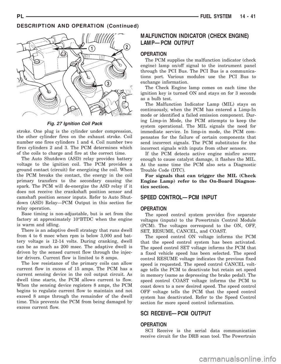
stroke. One plug is the cylinder under compression,
the other cylinder fires on the exhaust stroke. Coil
number one fires cylinders 1 and 4. Coil number two
fires cylinders 2 and 3. The PCM determines which
of the coils to charge and fire at the correct time.
The Auto Shutdown (ASD) relay provides battery
voltage to the ignition coil. The PCM provides a
ground contact (circuit) for energizing the coil. When
the PCM breaks the contact, the energy in the coil
primary transfers to the secondary causing the
spark. The PCM will de-energize the ASD relay if it
does not receive the crankshaft position sensor and
camshaft position sensor inputs. Refer to Auto Shut-
down (ASD) RelayÐPCM Output in this section for
relay operation.
Base timing is non-adjustable, but is set from the
factory at approximately 10ÉBTDC when the engine
is warm and idling.
There is an adaptive dwell strategy that runs dwell
from 4 to 6 msec when rpm is below 3,000 and bat-
tery voltage is 12-14 volts. During cranking, dwell
can be as much as 200 msec. The adaptive dwell is
driven by the sensed current flow through the injec-
tor drivers. Current flow is limited to 8 amps.
The low resistance of the primary coils can allow
current flow in excess of 15 amps. The PCM has a
current sensing device in the coil output circuit. As
dwell time starts, the PCM allows current to flow.
When the sensing device registers 8 amps, the PCM
begins to regulate current flow to maintain and not
exceed 8 amps through the remainder of the dwell
time. This prevents the PCM from being damaged by
excess current flow.
MALFUNCTION INDICATOR (CHECK ENGINE)
LAMPÐPCM OUTPUT
OPERATION
The PCM supplies the malfunction indicator (check
engine) lamp on/off signal to the instrument panel
through the PCI Bus. The PCI Bus is a communica-
tions port. Various modules use the PCI Bus to
exchange information.
The Check Engine lamp comes on each time the
ignition key is turned ON and stays on for 3 seconds
as a bulb test.
The Malfunction Indicator Lamp (MIL) stays on
continuously, when the PCM has entered a Limp-In
mode or identified a failed emission component. Dur-
ing Limp-in Mode, the PCM attempts to keep the
system operational. The MIL signals the need for
immediate service. In limp-in mode, the PCM com-
pensates for the failure of certain components that
send incorrect signals. The PCM substitutes for the
incorrect signals with inputs from other sensors.
If the PCM detects active engine misfire severe
enough to cause catalyst damage, it flashes the MIL.
At the same time the PCM also sets a Diagnostic
Trouble Code (DTC).
For signals that can trigger the MIL (Check
Engine Lamp) refer to the On-Board Diagnos-
tics section.
SPEED CONTROLÐPCM INPUT
OPERATION
The speed control system provides five separate
voltages (inputs) to the Powertrain Control Module
(PCM). The voltages correspond to the ON, OFF,
SET, RESUME, CANCEL, and COAST.
The speed control ON voltage informs the PCM
that the speed control system has been activated.
The speed control SET voltage informs the PCM that
a fixed vehicle speed has been selected. The speed
control RESUME voltage indicates the previous fixed
speed is requested. The speed control CANCEL volt-
age tells the PCM to deactivate but retain set speed
in memory (same as depressing the brake pedal). The
speed control COAST voltage informs the PCM to
coast down to a new desired speed. The speed control
OFF voltage tells the PCM that the speed control
system has deactivated. Refer to the Speed Control
section for more speed control information.
SCI RECEIVEÐPCM OUTPUT
OPERATION
SCI Receive is the serial data communication
receive circuit for the DRB scan tool. The Powertrain
Fig. 27 Ignition Coil Pack
PLFUEL SYSTEM 14 - 41
DESCRIPTION AND OPERATION (Continued)
Page 954 of 1285
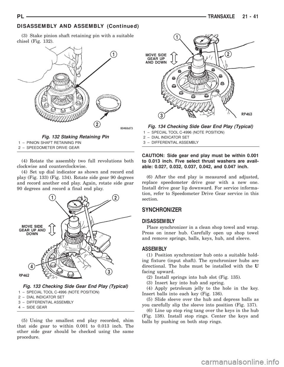
(3) Stake pinion shaft retaining pin with a suitable
chisel (Fig. 132).
(4) Rotate the assembly two full revolutions both
clockwise and counterclockwise.
(4) Set up dial indicator as shown and record end
play (Fig. 133) (Fig. 134). Rotate side gear 90 degrees
and record another end play. Again, rotate side gear
90 degrees and record a final end play.
(5) Using the smallest end play recorded, shim
that side gear to within 0.001 to 0.013 inch. The
other side gear should be checked using the same
procedure.CAUTION: Side gear end play must be within 0.001
to 0.013 inch. Five select thrust washers are avail-
able: 0.027, 0.032, 0.037, 0.042, and 0.047 inch.
(6) After the end play is measured and adjusted,
replace speedometer drive gear with a new one.
Install drive gear lip downward. For service informa-
tion, refer to Speedometer Drive Gear service in this
section.
SYNCHRONIZER
DISASSEMBLY
Place synchronizer in a clean shop towel and wrap.
Press on inner hub. Carefully open up shop towel
and remove springs, balls, keys, hub, and sleeve.
ASSEMBLY
(1) Position synchronizer hub onto a suitable hold-
ing fixture (input shaft). The synchronizer hubs are
directional. The hubs must be installed with theU
facing upward.
(2) Install springs into hub slot (Fig. 135).
(3) Insert key into hub and spring.
(4) Apply petroleum jelly to the hole in the key.
Insert balls into each key (Fig. 136).
(5) Slide sleeve over the hub and depress balls as
you carefully slip the sleeve into position (Fig. 137).
(6) Line up stop ring tang over the keys in the hub
(Fig. 138). Install stop rings. Center the keys and
balls by pushing on both stop rings.
Fig. 132 Staking Retaining Pin
1 ± PINION SHAFT RETAINING PIN
2 ± SPEEDOMETER DRIVE GEAR
Fig. 133 Checking Side Gear End Play (Typical)
1 ± SPECIAL TOOL C-4996 (NOTE POSITION)
2 ± DIAL INDICATOR SET
3 ± DIFFERENTIAL ASSEMBLY
4 ± SIDE GEAR
Fig. 134 Checking Side Gear End Play (Typical)
1 ± SPECIAL TOOL C-4996 (NOTE POSITION)
2 ± DIAL INDICATOR SET
3 ± DIFFERENTIAL ASSEMBLY
PLTRANSAXLE 21 - 41
DISASSEMBLY AND ASSEMBLY (Continued)
Page 1046 of 1285
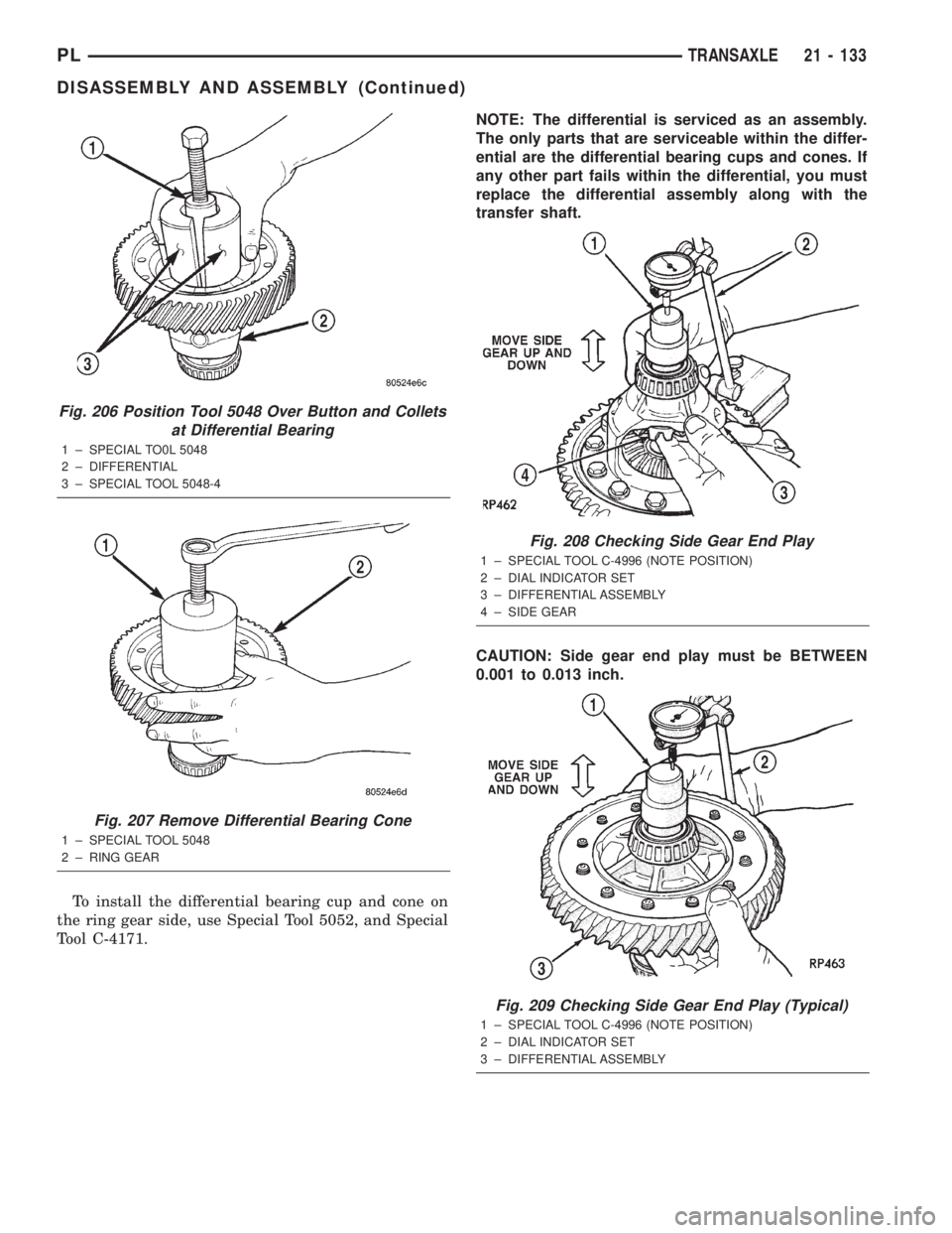
To install the differential bearing cup and cone on
the ring gear side, use Special Tool 5052, and Special
Tool C-4171.NOTE: The differential is serviced as an assembly.
The only parts that are serviceable within the differ-
ential are the differential bearing cups and cones. If
any other part fails within the differential, you must
replace the differential assembly along with the
transfer shaft.
CAUTION: Side gear end play must be BETWEEN
0.001 to 0.013 inch.
Fig. 206 Position Tool 5048 Over Button and Collets
at Differential Bearing
1 ± SPECIAL TO0L 5048
2 ± DIFFERENTIAL
3 ± SPECIAL TOOL 5048-4
Fig. 207 Remove Differential Bearing Cone
1 ± SPECIAL TOOL 5048
2 ± RING GEAR
Fig. 208 Checking Side Gear End Play
1 ± SPECIAL TOOL C-4996 (NOTE POSITION)
2 ± DIAL INDICATOR SET
3 ± DIFFERENTIAL ASSEMBLY
4 ± SIDE GEAR
Fig. 209 Checking Side Gear End Play (Typical)
1 ± SPECIAL TOOL C-4996 (NOTE POSITION)
2 ± DIAL INDICATOR SET
3 ± DIFFERENTIAL ASSEMBLY
PLTRANSAXLE 21 - 133
DISASSEMBLY AND ASSEMBLY (Continued)
Page 1070 of 1285
TIRES AND WHEELS
TABLE OF CONTENTS
page page
TIRES................................... 1WHEELS................................ 10
TIRES
TABLE OF CONTENTS
page page
DESCRIPTION AND OPERATION
TIRE...................................1
RADIAL-PLY TIRES........................2
SPARE TIRE±TEMPORARY..................3
REPLACEMENT TIRES.....................3
DIAGNOSIS AND TESTING
TREAD WEAR INDICATORS.................3
TIRE WEAR PATTERNS.....................4
TIRE NOISE OR VIBRATION.................4
VEHICLE LEAD DIAGNOSIS AND
CORRECTION..........................4
SERVICE PROCEDURES
PRESSURE GAUGES......................6TIRE INFLATION PRESSURES...............6
TIRE PRESSURE FOR HIGH SPEED
OPERATION............................6
TIRE AND WHEEL ROTATION................6
REPAIRING TIRE LEAKS....................7
TIRE AND WHEEL MATCH MOUNTING.........7
CLEANING AND INSPECTION
CLEANING TIRES.........................9
SPECIFICATIONS
TIRE SPECIFICATIONS.....................9
DESCRIPTION AND OPERATION
TIRE
Tires are designed and engineered for each specific
vehicle (Fig. 1). They provide the best overall perfor-
mance for normal operation. The ride and handling
characteristics match the vehicle's requirements.
With proper care they will give excellent reliability,
traction, skid resistance, and tread life.
Driving habits have more effect on tire life than
any other factor. Careful drivers will obtain, in most
cases, much greater mileage than severe use or care-
less drivers. A few of the driving habits which will
shorten the life of any tire are:²Rapid acceleration
²Severe application of brakes
²High-speed driving
²Taking turns at excessive speeds
²Striking curbs and other obstacles
²Operating vehicle with over or under inflated
tire pressures
Radial ply tires are more prone to irregular tread
wear. It is important to follow the tire rotation inter-
val shown in the section on Tire Rotation. This will
help to achieve a greater tread-life potential.
PLTIRES AND WHEELS 22 - 1