2000 DODGE NEON service indicator
[x] Cancel search: service indicatorPage 314 of 1285
LAMP BULB SERVICE
TABLE OF CONTENTS
page page
DESCRIPTION AND OPERATION
BULB...................................7
REMOVAL AND INSTALLATION
HEADLAMP BULB.........................7
FOG LAMP BULB..........................8
PARK AND TURN SIGNAL LAMP BULB.........8
FRONT SIDE MARKER LAMP BULB...........9
CENTER HIGH MOUNTED STOP LAMP BULB....9
TAIL, STOP, BACK-UP AND TURN SIGNAL
LAMP BULB............................9LICENSE PLATE LAMP BULB...............10
UNDERHOOD LAMP BULB.................10
REAR CARGO LAMP BULB.................10
DOME LAMP BULB.......................10
TRANSAXLE RANGE INDICATOR LAMP BULB . . 10
GLOVE BOX LAMP BULB...................11
FLOOR CONSOLE LAMP BULB..............11
VISOR VANITY LAMP BULB.................11
DESCRIPTION AND OPERATION
BULB
The electric light bulb is a source of electromag-
netic radiation which generates light. Vehicles use
many different types of bulbs:
²Headlamp bulb
²Fog Lamp bulb
²Tail Lamp bulb
²Stop Lamp bulb
²Turn Signal bulb
²Back up Lamp bulb
²Dome Lamp bulb
²Transaxle Range Indicator Lamp bulb (PRNDL)
²Glove Box Lamp bulb
²Floor Console Lamp bulb
²Rear Cargo Lamp bulb
²Visor Vanity Lamp bulb
²Underhood Lamp bulb
²etc.
REMOVAL AND INSTALLATION
HEADLAMP BULB
REMOVAL
(1) Release hood latch and open hood.
(2) Remove screws attaching headlamp module to
upper crossmember.
(3) Remove headlamp module from vehicle.
(4) Disconnect wire connector from back of head-
lamp bulb.
(5) Rotate retaining ring counterclockwise one
quarter turn.
(6) Remove retaining ring from headlamp module.
(7) Remove bulb from headlamp module (Fig. 1).
INSTALLATION
CAUTION: Do not touch the glass of halogen bulbs
with fingers or other possibly oily surface, reduced
bulb life will result.
(1) Install bulb into headlamp module.
(2) Install retaining ring to headlamp module.
(3) Rotate retaining ring clockwise one quarter
turn.
(4) Connect wire connector to the back of head-
lamp bulb.
(5) Place headlamp module in position.
(6) Install screws attaching headlamp module to
upper crossmember.
(7) Close hood.
PLLAMPS 8L - 7
Page 319 of 1285
LAMP SERVICE
TABLE OF CONTENTS
page page
DESCRIPTION AND OPERATION
LAMP ASSEMBLIES.......................12
REMOVAL AND INSTALLATION
HEADLAMP MODULE.....................12
FOG LAMP..............................13
PARK AND TURN SIGNAL LAMP BULB........13
FRONT SIDE MARKER LAMP...............13
CENTER HIGH MOUNTED STOP LAMP
(CHMSL)..............................14TAIL, STOP AND TURN SIGNAL LAMP........14
LICENSE PLATE LAMP....................14
UNDERHOOD LAMP......................14
REAR CARGO LAMP......................15
DOME LAMP............................15
GLOVE BOX LAMP BULB..................15
FLOOR CONSOLE LAMP BULB..............15
VISOR VANITY LAMP......................15
DESCRIPTION AND OPERATION
LAMP ASSEMBLIES
The lamp assemblies or modules generally consist
of a housing, reflector(s) and lens that directs a light
source. Vehicles use many different types of lamps:
²Headlamp
²Fog Lamp
²Tail Lamp
²Stop Lamp
²Turn Signal Lamp
²Back up Lamp
²Dome Lamp
²Transaxle Range Indicator Lamp (PRNDL)
²Glove Box Lamp
²Floor Console Lamp
²Rear Cargo Lamp
²Visor Vanity Lamp
²Underhood Lamp
²etc.
REMOVAL AND INSTALLATION
HEADLAMP MODULE
REMOVAL
(1) Release hood latch and open hood.
(2) Remove screws attaching headlamp module to
upper crossmember.
(3) Remove headlamp module from vehicle.
(4) Disconnect wire connectors from back of head-
lamp module.
(5) Remove headlamp module (Fig. 1).
INSTALLATION
CAUTION: Do not touch the glass of halogen bulbs
with fingers or other possibly oily surface, reduced
bulb life will result.
(1) Connect wire connectors to the back of head-
lamp module.
(2) Place headlamp module in position.
(3) Install screws attaching headlamp module to
upper crossmember.
(4) Close hood.
8L - 12 LAMPSPL
Page 324 of 1285
BULB APPLICATION
TABLE OF CONTENTS
page page
SPECIFICATIONS
EXTERIOR LAMPS........................17INTERIOR LAMPS........................17
SPECIFICATIONS
EXTERIOR LAMPS
CAUTION: Do not use bulbs that have a higher can-
dle power than the bulb listed in the chart below.
Damage to lamp can result. Do not touch halogen
bulbs with fingers or other oily surfaces. Bulb life
will be reduced.
LAMP BULB
Back Up Lamp................3157 ± P27/7W
Center High Mounted Stop Lamp
(CHMSL).........................W16W
Front Fog Lamp..................... GE881
Front Park/Turn Signal Lamp..........3157NA
Front Side Marker Lamp................. 168
Headlamp............................9007
License Plate Lamp..................... 168
Rear Tail/Stop/
Turn Signal Lamp............3157 ± P27/7W
INTERIOR LAMPS
Service procedures for most of the lamps in the
instrument panel, Instrument cluster and switches
are located in Group 8E, Instrument Panel and
Gauges.
CAUTION: Do not use bulbs that have a higher can-
dle power than the bulb listed in the chart below.
Damage to lamp can result.LAMP BULB
ABS Indicator......................... LED
Airbag Indicator....................... LED
Brake System Warning Indicator.......... LED
Climate Controls....................... LED
Console Gear Selector W/Auto...........PC194
Dome Lamp..........................T579
Floor Console Lamp..................... T37
Front Fog Lamp Indicator................ LED
Glove Compartment....................T194
High Beam Lamp Indicator.............PC194
Ignition Lock........................... 161
Instrument Cluster Illumination.........PC194
Low Fuel Indicator..................... LED
Low Oil Pressure Indicator............... LED
Rear Cargo...........................T906
Seat Belt Indicator..................... LED
Security Alarm Indicator................. LED
Malfunction Indicator Light.............. LED
TRAC OFF Indicator.................... LED
Turn Signal Indicator..................PC194
Underhood............................ 105
Visor Vanity........................6501966
Voltage Indicator....................... LED
All the inside bulbs brass or glass wedge base. Alu-
minum base bulbs are not approved and should not
be used for replacement.
PLLAMPS 8L - 17
Page 327 of 1285
HEADLAMP ALIGNMENT
TABLE OF CONTENTS
page page
DESCRIPTION AND OPERATION
HEADLAMP ALIGNMENT....................2
SERVICE PROCEDURES
HEADLAMP ALIGNMENT PREPARATION........2ADJUSTMENTS
HEADLAMP ADJUSTMENT USING
ALIGNMENT SCREEN....................2
DESCRIPTION AND OPERATION
HEADLAMP ALIGNMENT
Headlamps can be aligned using the screen method
provided in this section. This method will require the
vehicle to be parked on a flat, level surface with a
minimum of 15 meters of working room in front of a
flat, level perpendicular wall or aiming.
Each headlamp has a focal point circle molded on
the lens directly in front of each headlamp bulb.
These focal point circles are used to set up lines on a
wall, or aiming board for visually aiming the head-
lamps.
The driving (high) beam location does not require
adjustment. It will be correct when the passing (low)
beam headlamps are aimed correctly.
SERVICE PROCEDURES
HEADLAMP ALIGNMENT PREPARATION
(1) Verify headlamp dimmer switch and high beam
indicator operation.
(2) Inspect and correct damaged or defective com-
ponents that could interfere with proper headlamp
alignment.
(3) Verify that the headlamp leveling switch is in
the ª0º position.
(4) Verify proper tire inflation.
(5) Clean the headlamp lenses.
(6) Verify that the luggage area is not heavily
loaded.
(7) Fuel tank should be FULL. Add 2.94 kg (6.5
lbs.) of weight over the fuel tank for each estimated
gallon of missing fuel.
ADJUSTMENTS
HEADLAMP ADJUSTMENT USING ALIGNMENT
SCREEN
ALIGNMENT SCREEN PREPARATION
(1) Position the vehicle on a level surface 10
meters in front of a level, flat wall or aiming board.
(2) Tape a vertical line on the wall extending 1
meter up from the floor, making sure this line is even
with the centerline of the vehicle (Fig. 1).
(3) Measure the cross-car distance between the
two headlamp focal point circles (1174mm). Transfer
half of this distance (587mm) to the left of the vehicle
centerline and tape another vertical line up from the
floor 1 meter (Fig. 1). Repeat for the right side of the
centerline.
(4) Measure the distance from the floor to the focal
point circle on the headlamp lens (635mm, but may
vary due to variations in tire size and vehicle suspen-
sion height). Transfer this measurement to the wall
and tape a horizontal line extending approximately 1
meter beyond each vertical focal point line (Fig. 1).
(5) Use these lines for left and right adjustment
reference.
HEADLAMP ADJUSTMENT
Horizontal Adjustment
The horizontal position of the passing (low) beam
pattern is adjusted by turning the T-15 Torx screw.
Located through the slot in the upper-crossmember
between the two attaching straps of the headlamp.
Vertical Adjustment
The vertical position of the passing (low) beam pat-
tern is adjusted by turning the Phillips screw on top
of the headlamp leveling motor. Located between the
headlamp housing and the upper-crossmember, just
inboard of the fender.
Adjust the passing (low) beam headlamp pat-
terns to the locations shown in the chart pro-
vided (Fig. 1).
8L - 2 LAMPSPL
Page 344 of 1285
BULB APPLICATION
TABLE OF CONTENTS
page page
GENERAL INFORMATION
INTRODUCTION.........................19
SPECIFICATIONS
EXTERIOR LAMPS........................19INTERIOR LAMPS........................19
GENERAL INFORMATION
INTRODUCTION
The following Bulb Application Tables list the lamp
title on the left side of the column and trade number
or part number on the right.
CAUTION: Do not use bulbs that have a higher can-
dle power than the bulb listed in the Bulb Applica-
tion Table. Damage to lamp can result.
Do not touch halogen bulbs with fingers or other
possibly oily surfaces. Bulb life will be reduced.
If a halogen bulb is contaminated with oil, clean
bulb with denatured alcohol or ammonia based sol-
vent.
SPECIFICATIONS
EXTERIOR LAMPS
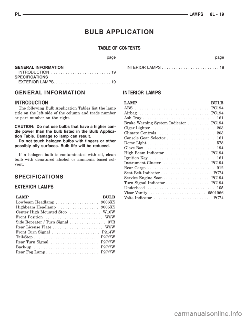
LAMP BULB
Lowbeam Headlamp..................9006XS
Highbeam Headlamp.................9005XS
Center High Mounted Stop.............W16W
Front Position........................ W5W
Side Repeater / Turn Signal............... 37R
Rear License Plate..................... W5W
Front Turn Signal....................P214W
Tail/Stop...........................P27/7W
Rear Turn Signal....................P27/7W
Back-up...........................P27/7W
Rear Fog Lamp......................P27/7W
INTERIOR LAMPS
LAMP BULB
ABS ...............................PC194
Airbag.............................PC194
AshTray .............................. 161
Brake Warning System Indicator.........PC194
Cigar Lighter.......................... 203
Climate Controls........................ 203
Console Gear Selector.................... 161
Dome Light............................ 578
Glove Box............................. 194
High Beam Indicator..................PC194
Ignition Key........................... 161
Instrument Cluster...................PC194
Rear Cargo............................ 912
Seat Belt Indicator.....................PC74
Service Engine Soon...................PC194
Turn Signal Indicator..................PC194
Underhood............................ 105
Visor Vanity........................6501966
Volts Indicator........................PC74
PLLAMPS 8L - 19
Page 358 of 1285
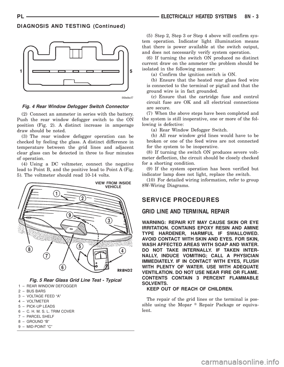
(2) Connect an ammeter in series with the battery.
Push the rear window defogger switch to the ON
position (Fig. 2). A distinct increase in amperage
draw should be noted.
(3) The rear window defogger operation can be
checked by feeling the glass. A distinct difference in
temperature between the grid lines and adjacent
clear glass can be detected in three to four minutes
of operation.
(4) Using a DC voltmeter, connect the negative
lead to Point B, and the positive lead to Point A (Fig.
5). The voltmeter should read 10-14 volts.(5) Step 2, Step 3 or Step 4 above will confirm sys-
tem operation. Indicator light illumination means
that there is power available at the switch output,
and does not necessarily verify system operation.
(6) If turning the switch ON produced no distinct
current draw on the ammeter the problem should be
isolated in the following manner:
(a) Confirm the ignition switch is ON.
(b) Ensure that the heated rear glass feed wire
is connected to the terminal or pigtail and that the
ground wire is in fact grounded.
(c) Ensure that the cartridge fuse and control
circuit fuse are OK and all electrical connections
are secure.
(7) When the above steps have been completed and
the system is still inoperative, one or more of the fol-
lowing is defective:
(a) Rear Window Defogger Switch.
(b) All rear window grid lines would have to be
broken or one of the feed wires are not connected
for the system to be inoperative.
(8) If turning the switch ON produces severe volt-
meter deflection, the circuit should be closely checked
for a shorting condition.
(9) If the system operation has been verified but
indicator lamp does not light, replace the switch.
(10) For detailed wiring information, refer to group
8W-Wiring Diagrams.
SERVICE PROCEDURES
GRID LINE AND TERMINAL REPAIR
WARNING: REPAIR KIT MAY CAUSE SKIN OR EYE
IRRITATION. CONTAINS EPOXY RESIN AND AMINE
TYPE HARDENER, HARMFUL IF SWALLOWED.
AVOID CONTACT WITH SKIN AND EYES. FOR SKIN,
WASH AFFECTED AREAS WITH SOAP AND WATER.
DO NOT TAKE INTERNALLY. IF TAKEN INTER-
NALLY, INDUCE VOMITING; CALL A PHYSICIAN
IMMEDIATELY. IF IN CONTACT WITH EYES, FLUSH
WITH PLENTY OF WATER. USE WITH ADEQUATE
VENTILATION. DO NOT USE NEAR FIRE OR FLAME.
CONTENTS CONTAIN 3 PERCENT FLAMMABLE
SOLVENTS.
KEEP OUT OF REACH OF CHILDREN.
The repair of the grid lines or the terminal is pos-
sible using the MopartRepair Package or equiva-
lent.
Fig. 4 Rear Window Defogger Switch Connector
Fig. 5 Rear Glass Grid Line Test - Typical
1 ± REAR WINDOW DEFOGGER
2 ± BUS BARS
3 ± VOLTAGE FEED ªAº
4 ± VOLTMETER
5 ± PICK-UP LEADS
6 ± C. H. M. S. L. TRIM COVER
7 ± PARCEL SHELF
8 ± GROUND ªBº
9 ± MID-POINT ªCº
PLELECTRICALLY HEATED SYSTEMS 8N - 3
DIAGNOSIS AND TESTING (Continued)
Page 372 of 1285
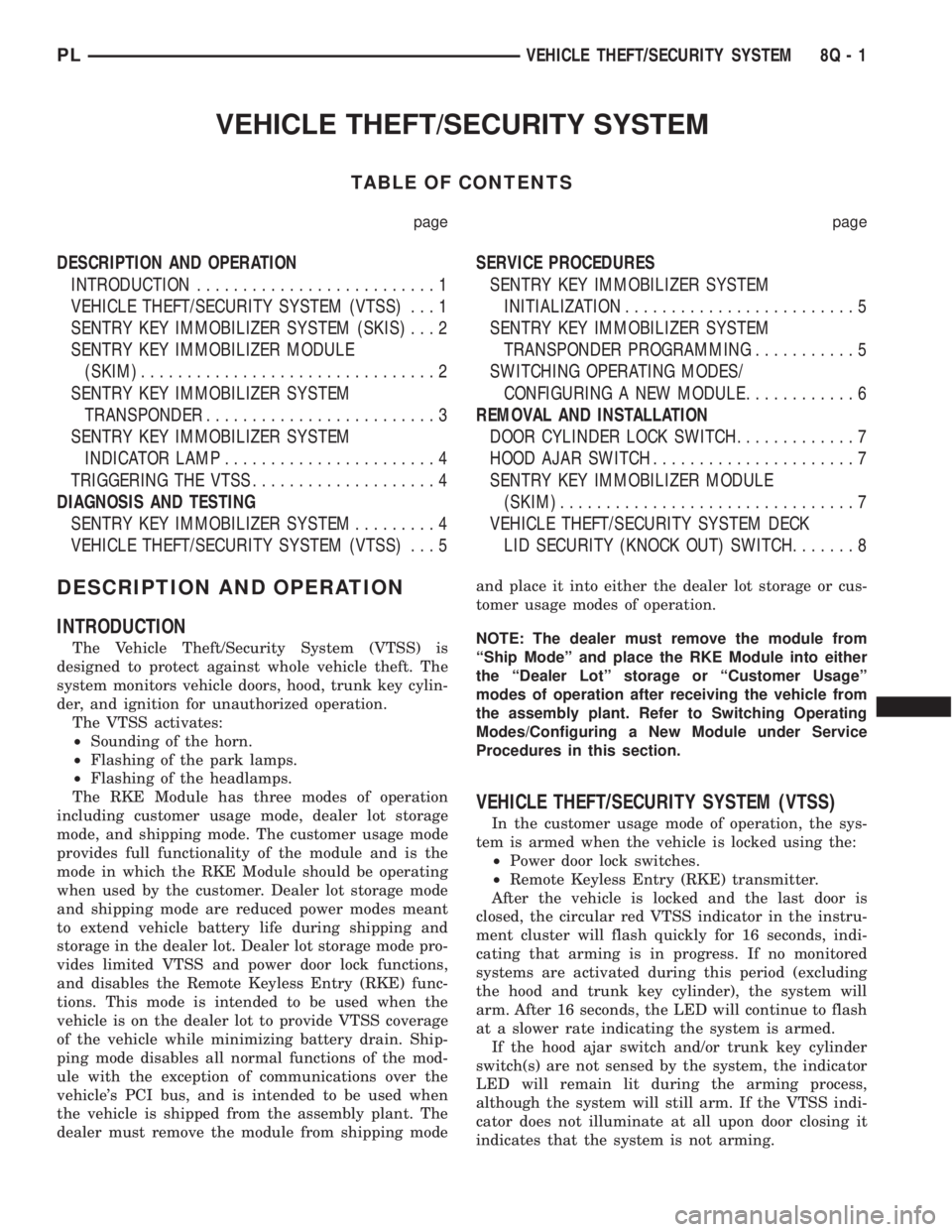
VEHICLE THEFT/SECURITY SYSTEM
TABLE OF CONTENTS
page page
DESCRIPTION AND OPERATION
INTRODUCTION..........................1
VEHICLE THEFT/SECURITY SYSTEM (VTSS)...1
SENTRY KEY IMMOBILIZER SYSTEM (SKIS)...2
SENTRY KEY IMMOBILIZER MODULE
(SKIM)................................2
SENTRY KEY IMMOBILIZER SYSTEM
TRANSPONDER.........................3
SENTRY KEY IMMOBILIZER SYSTEM
INDICATOR LAMP.......................4
TRIGGERING THE VTSS....................4
DIAGNOSIS AND TESTING
SENTRY KEY IMMOBILIZER SYSTEM.........4
VEHICLE THEFT/SECURITY SYSTEM (VTSS)...5SERVICE PROCEDURES
SENTRY KEY IMMOBILIZER SYSTEM
INITIALIZATION.........................5
SENTRY KEY IMMOBILIZER SYSTEM
TRANSPONDER PROGRAMMING...........5
SWITCHING OPERATING MODES/
CONFIGURING A NEW MODULE............6
REMOVAL AND INSTALLATION
DOOR CYLINDER LOCK SWITCH.............7
HOOD AJAR SWITCH......................7
SENTRY KEY IMMOBILIZER MODULE
(SKIM)................................7
VEHICLE THEFT/SECURITY SYSTEM DECK
LID SECURITY (KNOCK OUT) SWITCH.......8
DESCRIPTION AND OPERATION
INTRODUCTION
The Vehicle Theft/Security System (VTSS) is
designed to protect against whole vehicle theft. The
system monitors vehicle doors, hood, trunk key cylin-
der, and ignition for unauthorized operation.
The VTSS activates:
²Sounding of the horn.
²Flashing of the park lamps.
²Flashing of the headlamps.
The RKE Module has three modes of operation
including customer usage mode, dealer lot storage
mode, and shipping mode. The customer usage mode
provides full functionality of the module and is the
mode in which the RKE Module should be operating
when used by the customer. Dealer lot storage mode
and shipping mode are reduced power modes meant
to extend vehicle battery life during shipping and
storage in the dealer lot. Dealer lot storage mode pro-
vides limited VTSS and power door lock functions,
and disables the Remote Keyless Entry (RKE) func-
tions. This mode is intended to be used when the
vehicle is on the dealer lot to provide VTSS coverage
of the vehicle while minimizing battery drain. Ship-
ping mode disables all normal functions of the mod-
ule with the exception of communications over the
vehicle's PCI bus, and is intended to be used when
the vehicle is shipped from the assembly plant. The
dealer must remove the module from shipping modeand place it into either the dealer lot storage or cus-
tomer usage modes of operation.
NOTE: The dealer must remove the module from
ªShip Modeº and place the RKE Module into either
the ªDealer Lotº storage or ªCustomer Usageº
modes of operation after receiving the vehicle from
the assembly plant. Refer to Switching Operating
Modes/Configuring a New Module under Service
Procedures in this section.
VEHICLE THEFT/SECURITY SYSTEM (VTSS)
In the customer usage mode of operation, the sys-
tem is armed when the vehicle is locked using the:
²Power door lock switches.
²Remote Keyless Entry (RKE) transmitter.
After the vehicle is locked and the last door is
closed, the circular red VTSS indicator in the instru-
ment cluster will flash quickly for 16 seconds, indi-
cating that arming is in progress. If no monitored
systems are activated during this period (excluding
the hood and trunk key cylinder), the system will
arm. After 16 seconds, the LED will continue to flash
at a slower rate indicating the system is armed.
If the hood ajar switch and/or trunk key cylinder
switch(s) are not sensed by the system, the indicator
LED will remain lit during the arming process,
although the system will still arm. If the VTSS indi-
cator does not illuminate at all upon door closing it
indicates that the system is not arming.
PLVEHICLE THEFT/SECURITY SYSTEM 8Q - 1
Page 373 of 1285
VTSS disarming occurs upon normal vehicle entry
by unlocking either door via the key cylinders or
RKE transmitter, or by starting the vehicle with a
valid Sentry Key. This disarming will also halt the
alarm once it has been activated.
A tamper alert exists to notify the driver that the
system had been activated. This alert consists of 3
horn pulses when the vehicle is disarmed.
The VTSS will not arm by mechanically locking the
vehicle doors. This will manually override the sys-
tem.
In the dealer lot storage mode of operation, all of
the above descriptions of the VTSS are true with the
following exceptions:
²Remote Keyless Entry functions are disabled,
and cannot be used for arming/disarming the VTSS.
²The VTSS indicator is non-operational.
SENTRY KEY IMMOBILIZER SYSTEM (SKIS)
The Sentry Key Immobilizer System (SKIS) is
designed to provide passive protection against unau-
thorized vehicle use by preventing the engine from
operating while the system is armed. The primary
components of this system are the Sentry Key Immo-
bilizer Module (SKIM), the Sentry Key transponder,
the Vehicle Theft/Security System (VTSS) indicator
LED, and the Powertrain Control Module (PCM).
The SKIM is installed on the steering column near
the ignition lock cylinder. The transponder is located
under the molded rubber cap on the head of the igni-
tion key. The VTSS indicator LED is located in the
instrument cluster.
The SKIS includes three valid Sentry Key tran-
sponders from the factory, one being a valet key. This
is so the customer can self program new keys if one
is lost. If the customer wishes, additional non-coded
blank Sentry Keys are available. These blank keys
can be cut to match a valid ignition key, but the
engine will not start unless the key transponder is
also programmed to the vehicle. The SKIS will recog-
nize no more than eight valid Sentry Key transpon-
ders at any one time.
The SKIS performs a self-test each time the igni-
tion switch is turned to the ON position, and will
store Diagnostic Trouble Codes (DTC's) if a system
malfunction is detected. The SKIS can be diagnosed,
and any stored DTC can be retrieved using a DRB
llltscan tool as described in the proper Body Diag-
nostic Procedures Manual.
SENTRY KEY IMMOBILIZER MODULE (SKIM)
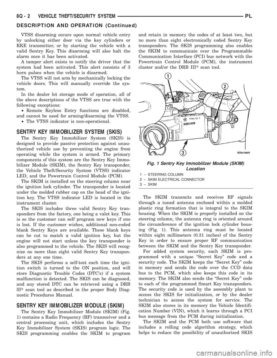
The Sentry Key Immobilizer Module (SKIM) (Fig.
1) contains a Radio Frequency (RF) transceiver and a
central processing unit, which includes the Sentry
Key Immobilizer System (SKIS) program logic. The
SKIS programming enables the SKIM to programand retain in memory the codes of at least two, but
no more than eight electronically coded Sentry Key
transponders. The SKIS programming also enables
the SKIM to communicate over the Programmable
Communication Interface (PCI) bus network with the
Powertrain Control Module (PCM), the instrument
cluster and/or the DRB IIItscan tool.
The SKIM transmits and receives RF signals
through a tuned antenna enclosed within a molded
plastic ring formation that is integral to the SKIM
housing. When the SKIM is properly installed on the
steering column, the antenna ring is oriented around
the circumference of the ignition lock cylinder hous-
ing (Fig. 1). This antenna ring must be located
within eight millimeters (0.31 inches) of the Sentry
Key in order to ensure proper RF communication
between the SKIM and the Sentry Key transponder.
For added system security, each SKIM is pro-
grammed with a unique ªSecret Keyº code and a
security code. The SKIM keeps the ªSecret Keyº code
in memory and sends the code over the CCD data
bus to the PCM, which also keeps this code in its
memory. The SKIM also sends the ªSecret Keyº code
to each of the programmed Smart Key transponders.
The security code is used by the assembly plant to
access the SKIS for initialization, or by the dealer
technician to access the system for service. The
SKIM also stores in its memory the Vehicle Identifi-
cation Number (VIN), which it learns through a PCI
bus message from the PCM during initialization.
The SKIM and the PCM both use software that
includes a rolling code algorithm strategy, which
helps to reduce the possibility of unauthorized SKIS
Fig. 1 Sentry Key Immobilizer Module (SKIM)
Location
1 ± STEERING COLUMN
2 ± SKIM ELECTRICAL CONNECTOR
3 ± SKIM
8Q - 2 VEHICLE THEFT/SECURITY SYSTEMPL
DESCRIPTION AND OPERATION (Continued)