2000 DODGE NEON gas type
[x] Cancel search: gas typePage 20 of 1285
FRONT SUSPENSION
TABLE OF CONTENTS
page page
DESCRIPTION AND OPERATION
FRONT SUSPENSION SYSTEM...............9
STRUT ASSEMBLY (FRONT)................11
STEERING KNUCKLE.....................11
LOWER CONTROL ARM...................11
STABILIZER BAR (FRONT).................12
DIAGNOSIS AND TESTING
STRUT ASSEMBLY (FRONT)................12
STEERING KNUCKLE.....................13
WHEEL BEARING AND HUB................13
LOWER CONTROL ARM...................13
BALL JOINT.............................13
STABILIZER BAR (FRONT).................14
SERVICE PROCEDURES
LUBRICATION...........................14
REMOVAL AND INSTALLATION
SERVICE WARNINGS AND CAUTIONS........14STRUT ASSEMBLY (FRONT)................14
STEERING KNUCKLE.....................15
LOWER CONTROL ARM...................18
STABILIZER BAR (FRONT).................20
WHEEL MOUNTING STUD (FRONT)..........21
DISASSEMBLY AND ASSEMBLY
STRUT ASSEMBLY (FRONT)................22
STEERING KNUCKLE (WHEEL BEARING AND
HUB).................................25
LOWER CONTROL ARM (BALL JOINT)........29
LOWER CONTROL ARM (REAR ISOLATOR
BUSHING).............................31
SPECIFICATIONS
FRONT SUSPENSION FASTENER TORQUE
SPECIFICATIONS.......................33
SPECIAL TOOLS
FRONT SUSPENSION.....................33
DESCRIPTION AND OPERATION
FRONT SUSPENSION SYSTEM
The front suspension allows each front wheel on a
vehicle to adapt to different road surfaces and condi-
tions without greatly affecting the opposite wheel
and the ability to control the vehicle. Each side of the
front suspension is allowed to pivot so the vehicle can
be steered in the direction preferred.
This vehicle has a gas pressurized MacPherson
strut type front suspension design (Fig. 1).A strut assembly is used in place of the front sus-
pension upper control arm and upper ball joint.
When a vehicle strikes a bump, the force is trans-
ferred through the hub, bearing, and knuckle, into
the strut assembly to absorb the force and dampen it.
The top of the strut is mounted directly to the strut
tower of the vehicle. During steering maneuvers, the
strut assembly (through a pivot bearing in the upper
strut mount) and steering knuckle (through the lower
ball joint mounted on the lower control arm) turn as
an assembly.
PLSUSPENSION 2 - 9
Page 207 of 1285
SHROUD
REMOVAL
(1) Remove cooling fan module. Refer to procedure
in this section.
(2) Remove fan and fan motor as previously
described.
INSTALLATION
(1) Install fan motor and fan as previously
described.
(2) Install cooling fan module. Refer to procedure
in this section.
CLEANING AND INSPECTION
WATER PUMP
Replace water pump body assembly if it has any of
these defects:
(1) Cracks or damage on the body.
(2) Coolant leaks from the shaft seal, evident by
coolant traces on the pump body.
(3) Loose or rough turning bearing.
(4) Impeller rubs either the pump body or the
engine block.
(5) Impeller loose or damaged.
(6) Sprocket or sprocket flange loose or damaged.
ACCESSORY DRIVE BELT INSPECTION
Belt replacement under any or all of the following
conditions is required, excessive wear, frayed cords or
severe glazing.
Poly-V Belt system may develop minor cracks
across the ribbed side. These minor cracks are con-
sidered normal and acceptable. Cracks parallel are
not (Fig. 40).
NOTE: Do not use any type of belt dressing or
restorer on Poly-V Belts.
COOLING SYSTEM CAP
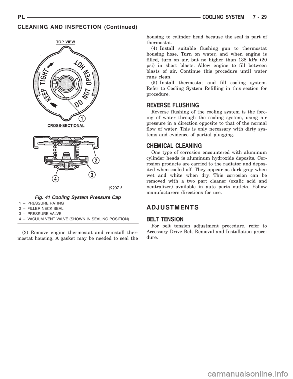
Hold the cap in your hand,right side up(Fig. 41).
The vent valve at the bottom of the cap should open
with a slight pull. If the rubber gasket has swollen,
preventing the valve from opening, replace the cap.
If any light can be seen between vent valve and
the rubber gasket, replace the cap.Use only a
replacement cap that has a spring to hold the
vent shut.
A replacement cap must be of the type designed for
coolant reserve systems. This design ensures system
pressurization.
COOLING SYSTEM CLEANING
(1) Drain cooling system. Refer to Cooling System
Draining in this section for procedure.
(2) Refill with clean water. Refer to Cooling Sys-
tem Refilling in this section for procedure.
(3) Run engine with radiator cap installed until
upper radiator hose is hot.
(4) Stop engine and drain water from system. If
water is dirty, fill, run and drain the system again
until water runs clear.
RADIATOR FLUSHING
(1) Drain cooling system. Refer to Cooling System
Draining in this section for procedure.
(2) Remove radiator hoses from engine.
(3) Install suitable flushing gun in radiator lower
hose.
(4) Fill radiator with clean water and turn on air
in short blasts.
CAUTION: Internal radiator pressure must not
exceed 138 kPa (20 psi) as damage to radiator may
result. Continue this procedure until water runs
clear.
ENGINE FLUSHING
(1) Drain radiator. Refer to Cooling System Drain-
ing in this section for procedure.
(2) Remove hoses from radiator.
Fig. 40 Drive Belt Wear Pattern
1 ± NORMAL CRACKS BELT OK
2 ± NOT NORMAL CRACKS REPLACE BELT
7 - 28 COOLING SYSTEMPL
DISASSEMBLY AND ASSEMBLY (Continued)
Page 208 of 1285
(3) Remove engine thermostat and reinstall ther-
mostat housing. A gasket may be needed to seal thehousing to cylinder head because the seal is part of
thermostat.
(4) Install suitable flushing gun to thermostat
housing hose. Turn on water, and when engine is
filled, turn on air, but no higher than 138 kPa (20
psi) in short blasts. Allow engine to fill between
blasts of air. Continue this procedure until water
runs clean.
(5) Install thermostat and fill cooling system.
Refer to Cooling System Refilling in this section for
procedure.
REVERSE FLUSHING
Reverse flushing of the cooling system is the forc-
ing of water through the cooling system, using air
pressure in a direction opposite to that of the normal
flow of water. This is only necessary with dirty sys-
tems and evidence of partial plugging.
CHEMICAL CLEANING
One type of corrosion encountered with aluminum
cylinder heads is aluminum hydroxide deposits. Cor-
rosion products are carried to the radiator and depos-
ited when cooled off. They appear as dark grey when
wet and white when dry. This corrosion can be
removed with a two part cleaner (oxalic acid and
neutralizer) available in auto parts outlets. Follow
manufacturers directions for use.
ADJUSTMENTS
BELT TENSION
For belt tension adjustment procedure, refer to
Accessory Drive Belt Removal and Installation proce-
dure.
Fig. 41 Cooling System Pressure Cap
1 ± PRESSURE RATING
2 ± FILLER NECK SEAL
3 ± PRESSURE VALVE
4 ± VACUUM VENT VALVE (SHOWN IN SEALING POSITION)
PLCOOLING SYSTEM 7 - 29
CLEANING AND INSPECTION (Continued)
Page 724 of 1285
ENGINE
TABLE OF CONTENTS
page page
STANDARD SERVICE PROCEDURES........... 1
ENGINE DIAGNOSIS........................ 82.0L SOHC ENGINE....................... 15
STANDARD SERVICE PROCEDURES
TABLE OF CONTENTS
page page
GENERAL INFORMATION
FORM-IN-PLACE GASKETS & SEALERS........1
ENGINE GASKET SURFACE PREPARATION.....2
CRANKSHAFT DAMPER BOLT ACCESS PLUG . . . 2
ENGINE CORE PLUGS.....................2
ENGINE PERFORMANCE...................3HONING CYLINDER BORES.................3
MEASURING WITH PLASTIGAGE.............4
REPAIR OF DAMAGED OR WORN THREADS....5
HYDROSTATIC LOCKED ENGINE.............5
CHECKING ENGINE OIL LEVEL..............6
ENGINE OIL SERVICE......................7
GENERAL INFORMATION
FORM-IN-PLACE GASKETS & SEALERS
There are numerous places where form-in-place
gaskets are used on the engine. Care must be taken
when applying form-in-place gaskets to assure
obtaining the desired results.Do not use form-in-
place gasket material unless specified.Bead size,
continuity, and location are of great importance. Too
thin a bead can result in leakage while too much can
result in spill-over which can break off and obstruct
fluid feed lines. A continuous bead of the proper
width is essential to obtain a leak-free gasket.
There are numerous types of form-in-place gasket
materials that are used in the engine area. Mopart
Engine RTV GEN II, MopartATF-RTV, and Mopart
Gasket Maker gasket materials, each have different
properties and can not be used in place of the other.
MOPARtENGINE RTV GEN II
MopartEngine RTV GEN II is used to seal com-
ponents exposed to engine oil. This material is a spe-
cially designed black silicone rubber RTV that
retains adhesion and sealing properties when
exposed to engine oil. Moisture in the air causes the
material to cure. This material is available in three
ounce tubes and has a shelf life of one year. After one
year this material will not properly cure. Alwaysinspect the package for the expiration date before
use.
MOPARtATF RTV
MopartATF RTV is a specifically designed black
silicone rubber RTV that retains adhesion and seal-
ing properties to seal components exposed to auto-
matic transmission fluid, engine coolants, and
moisture. This material is available in three ounce
tubes and has a shelf life of one year. After one year
this material will not properly cure. Always inspect
the package for the expiration date before use.
MOPARtGASKET MAKER
MopartGasket Maker is an anaerobic type gasket
material. The material cures in the absence of air
when squeezed between two metallic surfaces. It will
not cure if left in the uncovered tube. The anaerobic
material is for use between two machined surfaces.
Do not use on flexible metal flanges.
MOPARtBED PLATE SEALANT
MopartBed Plate Sealant is a unique (green-in-
color) anaerobic type gasket material that is specially
made to seal the area between the bedplate and cyl-
inder block without disturbing the bearing clearance
or alignment of these components. The material
cures slowly in the absence of air when torqued
between two metallic surfaces, and will rapidly cure
when heat is applied.
PLENGINE 9 - 1
Page 730 of 1285
ENGINE OIL SERVICE
WARNING: NEW OR USED ENGINE OIL CAN BE
IRRITATING TO THE SKIN. AVOID PROLONGED OR
REPEATED SKIN CONTACT WITH ENGINE OIL.
CONTAMINANTS IN USED ENGINE OIL, CAUSED BY
INTERNAL COMBUSTION, CAN BE HAZARDOUS TO
YOUR HEALTH. THOROUGHLY WASH EXPOSED
SKIN WITH SOAP AND WATER. DO NOT WASH
SKIN WITH GASOLINE, DIESEL FUEL, THINNER, OR
SOLVENTS, HEALTH PROBLEMS CAN RESULT. DO
NOT POLLUTE, DISPOSE OF USED ENGINE OIL
PROPERLY. CONTACT YOUR DEALER OR GOVERN-
MENT AGENCY FOR LOCATION OF COLLECTION
CENTER IN YOUR AREA.
ENGINE OIL SPECIFICATION
CAUTION: Do not use non-detergent or straight
mineral oil when adding or changing crankcase
lubricant. Engine failure can result.
API SERVICE GRADE CERTIFIED
Use an engine oil that is API Service Grade Certi-
fied. MOPARtprovides engine oils that conforms to
this service grade.
SAE VISCOSITY
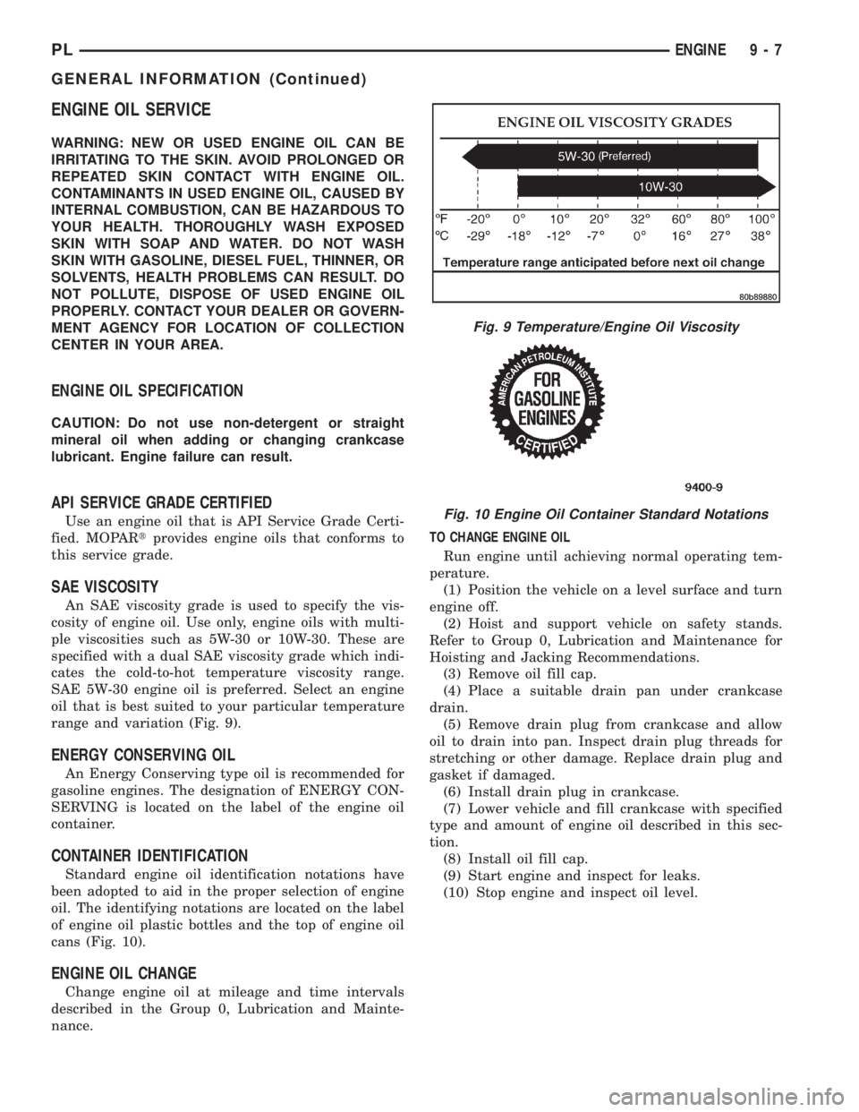
An SAE viscosity grade is used to specify the vis-
cosity of engine oil. Use only, engine oils with multi-
ple viscosities such as 5W-30 or 10W-30. These are
specified with a dual SAE viscosity grade which indi-
cates the cold-to-hot temperature viscosity range.
SAE 5W-30 engine oil is preferred. Select an engine
oil that is best suited to your particular temperature
range and variation (Fig. 9).
ENERGY CONSERVING OIL
An Energy Conserving type oil is recommended for
gasoline engines. The designation of ENERGY CON-
SERVING is located on the label of the engine oil
container.
CONTAINER IDENTIFICATION
Standard engine oil identification notations have
been adopted to aid in the proper selection of engine
oil. The identifying notations are located on the label
of engine oil plastic bottles and the top of engine oil
cans (Fig. 10).
ENGINE OIL CHANGE
Change engine oil at mileage and time intervals
described in the Group 0, Lubrication and Mainte-
nance.TO CHANGE ENGINE OIL
Run engine until achieving normal operating tem-
perature.
(1) Position the vehicle on a level surface and turn
engine off.
(2) Hoist and support vehicle on safety stands.
Refer to Group 0, Lubrication and Maintenance for
Hoisting and Jacking Recommendations.
(3) Remove oil fill cap.
(4) Place a suitable drain pan under crankcase
drain.
(5) Remove drain plug from crankcase and allow
oil to drain into pan. Inspect drain plug threads for
stretching or other damage. Replace drain plug and
gasket if damaged.
(6) Install drain plug in crankcase.
(7) Lower vehicle and fill crankcase with specified
type and amount of engine oil described in this sec-
tion.
(8) Install oil fill cap.
(9) Start engine and inspect for leaks.
(10) Stop engine and inspect oil level.
Fig. 9 Temperature/Engine Oil Viscosity
Fig. 10 Engine Oil Container Standard Notations
PLENGINE 9 - 7
GENERAL INFORMATION (Continued)
Page 740 of 1285
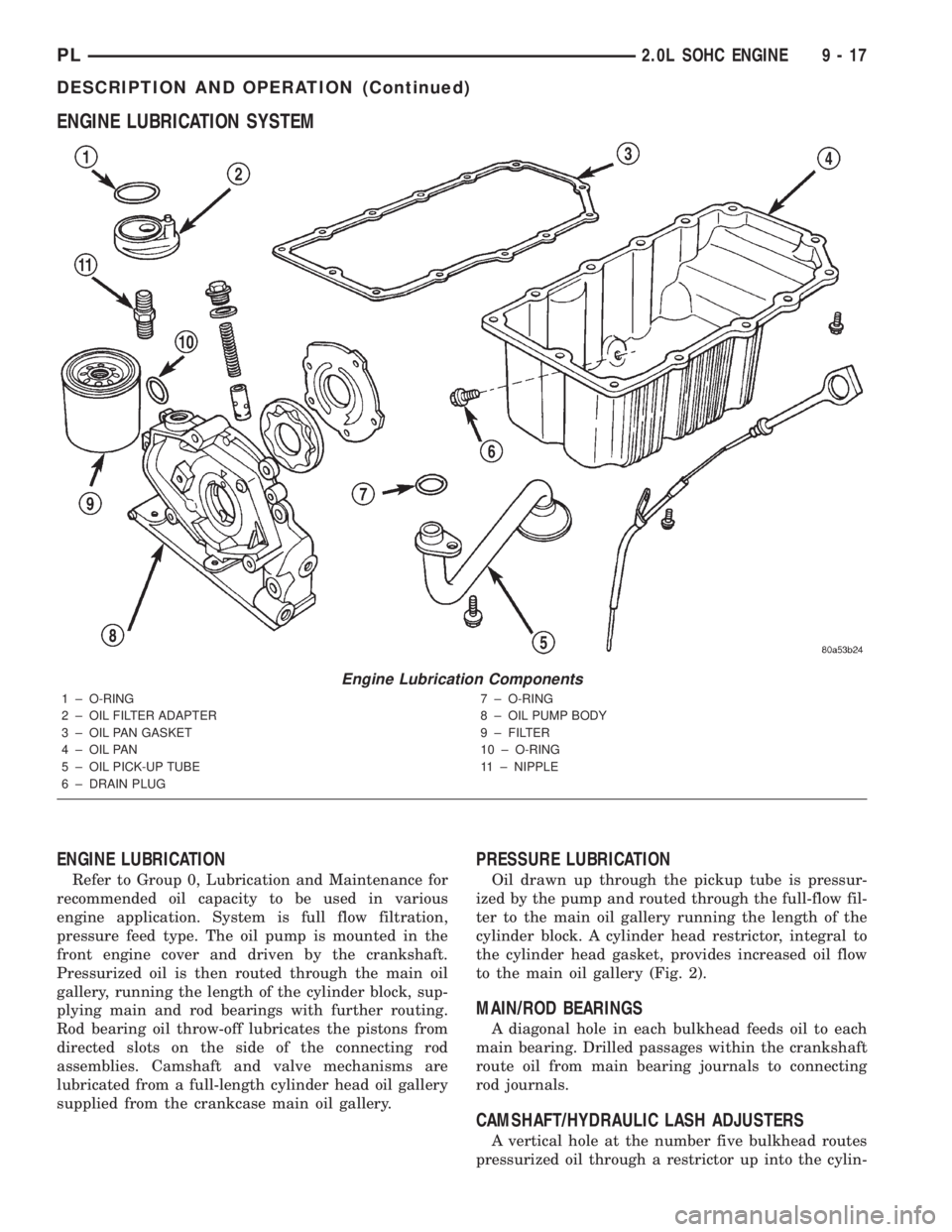
ENGINE LUBRICATION SYSTEM
ENGINE LUBRICATION
Refer to Group 0, Lubrication and Maintenance for
recommended oil capacity to be used in various
engine application. System is full flow filtration,
pressure feed type. The oil pump is mounted in the
front engine cover and driven by the crankshaft.
Pressurized oil is then routed through the main oil
gallery, running the length of the cylinder block, sup-
plying main and rod bearings with further routing.
Rod bearing oil throw-off lubricates the pistons from
directed slots on the side of the connecting rod
assemblies. Camshaft and valve mechanisms are
lubricated from a full-length cylinder head oil gallery
supplied from the crankcase main oil gallery.
PRESSURE LUBRICATION
Oil drawn up through the pickup tube is pressur-
ized by the pump and routed through the full-flow fil-
ter to the main oil gallery running the length of the
cylinder block. A cylinder head restrictor, integral to
the cylinder head gasket, provides increased oil flow
to the main oil gallery (Fig. 2).
MAIN/ROD BEARINGS
A diagonal hole in each bulkhead feeds oil to each
main bearing. Drilled passages within the crankshaft
route oil from main bearing journals to connecting
rod journals.
CAMSHAFT/HYDRAULIC LASH ADJUSTERS
A vertical hole at the number five bulkhead routes
pressurized oil through a restrictor up into the cylin-
Engine Lubrication Components
1 ± O-RING
2 ± OIL FILTER ADAPTER
3 ± OIL PAN GASKET
4 ± OIL PAN
5 ± OIL PICK-UP TUBE
6 ± DRAIN PLUG7 ± O-RING
8 ± OIL PUMP BODY
9 ± FILTER
10 ± O-RING
11 ± NIPPLE
PL2.0L SOHC ENGINE 9 - 17
DESCRIPTION AND OPERATION (Continued)
Page 824 of 1285
carbon monoxide emissions. The type and amount of
oxygenate used in the blend is important.
The following are generally used in gasoline
blends:
Ethanol- (Ethyl or Grain Alcohol) properly
blended, is used as a mixture of 10 percent ethanol
and 90 percent gasoline. Gasoline blended with etha-
nol may be used in your vehicle.
MTBE/ETBE- Gasoline and MTBE (Methyl Ter-
tiary Butyl Ether) blends are a mixture of unleaded
gasoline and up to 15 percent MTBE. Gasoline and
ETBE (Ethyl Tertiary Butyl Ether) are blends of gas-
oline and up to 17 percent ETBE. Gasoline blended
with MTBE or ETBE may be used in your vehicle.
Methanol- Methanol (Methyl or Wood Alcohol) is
used in a variety of concentrations blended with
unleaded gasoline. You may encounter fuels contain-
ing 3 percent or more methanol along with other
alcohols called cosolvents.
DO NOT USE GASOLINE CONTAINING
METHANOL.
Use of methanol/gasoline blends may result in
starting and driveability problems and damage criti-
cal fuel system components.
Problems that are the result of using methanol/
gasoline blends are not the responsibility of
DaimlerChrysler Corporation and may not be covered
by the vehicle warranty.
Reformulated Gasoline
Many areas of the country are requiring the use of
cleaner-burning fuel referred to asReformulated
Gasoline. Reformulated gasoline are specially
blended to reduce vehicle emissions and improve air
quality.
DaimlerChrysler Corporation strongly supports the
use of reformulated gasoline whenever available.
Although your vehicle was designed to provide opti-
mum performance and lowest emissions operating on
high quality unleaded gasoline, it will perform
equally well and produce even lower emissions when
operating on reformulated gasoline.
Materials Added to Fuel
Indiscriminate use of fuel system cleaning agents
should be avoided. Many of these materials intended
for gum and varnish removal may contain active sol-
vents of similar ingredients that can be harmful to
fuel system gasket and diaphragm materials.
FUEL DELIVERY SYSTEM
OPERATION
The fuel delivery system consists of: the electric
fuel pump, fuel filter/fuel pressure regulator, fuel
tubes/lines/hoses, fuel rail, fuel injectors, fuel tank,
accelerator pedal and throttle cable.A fuel return system is used on all models (all
engines). Fuel is returned through the fuel pump
module and back into the fuel tank through the fuel
filter/fuel pressure regulator. A separate fuel return
line from the engine to the tank is no longer used
with any engine.
The fuel tank assembly consists of: the fuel tank,
filler tube, fuel gauge sending unit/electric fuel pump
module, a rollover valve(s) and a pressure-vacuum
filler cap.
Also to be considered part of the fuel system is the
evaporation control system or Onboard Refueling
Vapor recovery (ORVR). This is designed to reduce
the emission of fuel vapors into the atmosphere. The
description and function of the Evaporative Control
System is found in the Emission Control Systems
section.
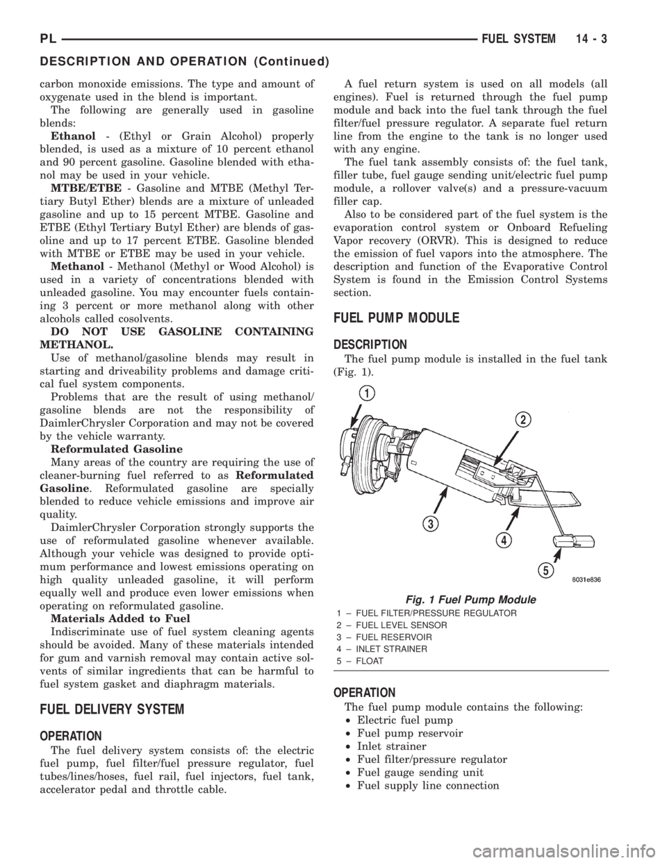
FUEL PUMP MODULE
DESCRIPTION
The fuel pump module is installed in the fuel tank
(Fig. 1).
OPERATION
The fuel pump module contains the following:
²Electric fuel pump
²Fuel pump reservoir
²Inlet strainer
²Fuel filter/pressure regulator
²Fuel gauge sending unit
²Fuel supply line connection
Fig. 1 Fuel Pump Module
1 ± FUEL FILTER/PRESSURE REGULATOR
2 ± FUEL LEVEL SENSOR
3 ± FUEL RESERVOIR
4 ± INLET STRAINER
5 ± FLOAT
PLFUEL SYSTEM 14 - 3
DESCRIPTION AND OPERATION (Continued)
Page 825 of 1285
The inlet strainer, fuel pressure regulator and fuel
level sensor are the only serviceable items. If the fuel
pump requires service, replace the fuel pump module.
ELECTRIC FUEL PUMP
DESCRIPTION
The electric fuel pump is located in and is part of
the fuel pump module. It is a positive displacement,
gerotor type, immersible pump with a permanent
magnet electric motor. The fuel pump module is sus-
pended in fuel in the fuel tank.
OPERATION
The pump draws fuel through a strainer and
pushes it through the motor to the outlet. The pump
contains a check valve. The valve, in the pump out-
let, maintains pump pressure during engine off con-
ditions. The fuel pump relay provides voltage to the
fuel pump. The fuel pump has a maximum dead-
headed pressure output of approximately 880 kPa
(130 psi). The regulator adjusts fuel system pressure
to approximately 338 kPa (49 psi).
FUEL GAUGE SENDING UNIT
DESCRIPTION
The fuel gauge sending unit (fuel level sensor) is
attached to the side of the fuel pump module. The
sending unit consists of a float, an arm, and a vari-
able resistor (track). The resistor track is used to
send electrical signals to the instrument cluster for
fuel gauge operation and are then transmitted to the
engine controller for OBDII emission requirements.
OPERATION
For fuel gauge operation:As fuel level
increases, the float and arm move up. This increases
the sending unit resistance, causing the fuel gauge to
read full. As fuel level decreases, the float and arm
move down. This decreases the sending unit resis-
tance causing the fuel gauge to read empty.
After this fuel level signal is sent to the instru-
ment cluster, the instrument cluster will transmit
the data across the J1850 bus circuit to the PCM.
For OBD II emission requirements:The voltage
signal is sent to the instrument cluster to indicate
fuel level. The cluster transmits the fuel level to the
PCM where it is used to prevent a false setting of
misfire and fuel system monitor trouble codes. This
occurs if the fuel level in the tank is less than
approximately 15 percent of its rated capacity.
FUEL FILTER/FUEL PRESSURE REGULATOR
DESCRIPTION
A combination fuel filter and fuel pressure regula-
tor is used on all gas powered engines. It is located
on the top of the fuel pump module. A separate frame
mounted fuel filter is not used.
OPERATION
Fuel Pressure Regulator Operation:The pres-
sure regulator is a mechanical device that is cali-
brated to maintain fuel system operating pressure of
approximately 338 kPa (49 psi) at the fuel injectors.
It contains a diaphragm, calibrated springs and a
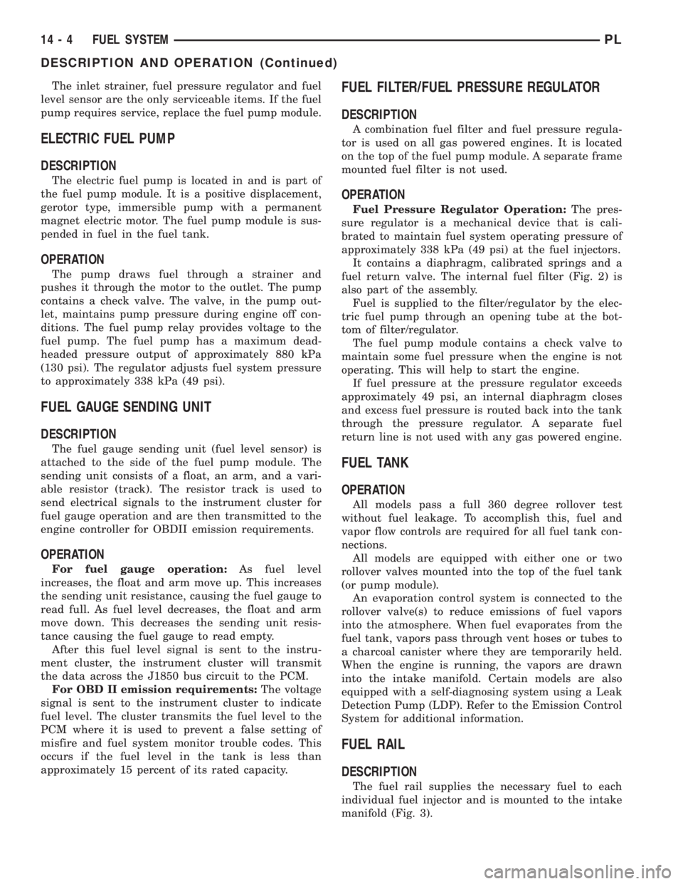
fuel return valve. The internal fuel filter (Fig. 2) is
also part of the assembly.
Fuel is supplied to the filter/regulator by the elec-
tric fuel pump through an opening tube at the bot-
tom of filter/regulator.
The fuel pump module contains a check valve to
maintain some fuel pressure when the engine is not
operating. This will help to start the engine.
If fuel pressure at the pressure regulator exceeds
approximately 49 psi, an internal diaphragm closes
and excess fuel pressure is routed back into the tank
through the pressure regulator. A separate fuel
return line is not used with any gas powered engine.
FUEL TANK
OPERATION
All models pass a full 360 degree rollover test
without fuel leakage. To accomplish this, fuel and
vapor flow controls are required for all fuel tank con-
nections.
All models are equipped with either one or two
rollover valves mounted into the top of the fuel tank
(or pump module).
An evaporation control system is connected to the
rollover valve(s) to reduce emissions of fuel vapors
into the atmosphere. When fuel evaporates from the
fuel tank, vapors pass through vent hoses or tubes to
a charcoal canister where they are temporarily held.
When the engine is running, the vapors are drawn
into the intake manifold. Certain models are also
equipped with a self-diagnosing system using a Leak
Detection Pump (LDP). Refer to the Emission Control
System for additional information.
FUEL RAIL
DESCRIPTION
The fuel rail supplies the necessary fuel to each
individual fuel injector and is mounted to the intake
manifold (Fig. 3).
14 - 4 FUEL SYSTEMPL
DESCRIPTION AND OPERATION (Continued)