2000 DODGE NEON brake light
[x] Cancel search: brake lightPage 4 of 1285
MAINTENANCE SCHEDULES
TABLE OF CONTENTS
page page
DESCRIPTION AND OPERATION
MAINTENANCE SCHEDULES................3
SPECIFICATIONS
UNSCHEDULED INSPECTION................3SCHEDULE ± A...........................3
SCHEDULE ± B...........................4
DESCRIPTION AND OPERATION
MAINTENANCE SCHEDULES
There are two maintenance schedules that show
proper service for your vehicle.
First is Schedule ±A. It lists all the scheduled
maintenance to be performed under ªnormalº operat-
ing conditions.
Second is Schedule ±B. It is a schedule for vehi-
cles that are operated under the following conditions:
²Frequent short trip driving less than 5 miles (8
km)
²Frequent driving in dusty conditions
²Extensive idling
²More than 50% of the driving is at sustained
high speeds during hot weather, above 90É F (32É C)
SPECIFICATIONS
UNSCHEDULED INSPECTION
At Each Stop For Fuel
²Check engine oil level and add as required.
²Check windshield washer solvent and add as
required.
Once A Month
²Check tire pressure and look for unusual wear
or damage.
²Inspect the battery and clean and tighten termi-
nals as required.
²Check fluid levels of coolant reservoir, brake
master cylinder, power steering and transmission.
Add fluid as required.
²Check all lights and all other electrical items for
correct operation.
At Each Oil Change
²Inspect the exhaust system.
²Inspect brake hoses.
²Inspect the CV joints and front suspension com-
ponent boots and seals.²Rotate the tires at each oil change interval
shown on Schedule ± A (7,500 miles - 12 000 km) or
every other interval on Schedule ± B (6,000 miles -
10 000 km).
²Check the engine coolant level, hoses, and
clamps.
If mileage is less than 7,500 miles (12 000 km)
yearly, replace the engine oil filter at each oil change.
EMISSION CONTROL SYSTEM MAINTENANCE
The scheduled emission maintenance listed inbold
typeon the Maintenance Schedules, must be done at
the mileage specified to assure the continued proper
functioning of the emission control system. These,
and all other maintenance services included in this
manual, should be done to provide the best vehicle
performance and reliability. More frequent mainte-
nance may be needed for vehicles in severe operating
conditions such as dusty areas and very short trip
driving.
FLUID FILL POINTS AND LUBRICATION
LOCATIONS
The fluid fill/check locations and lubrication loca-
tions are located in each applicable group.
SCHEDULE ± A
7,500 Miles (12 000 km) or at 6 months
²Change the engine oil.
²Replace the engine oil filter.
15,000 Miles (24 000 km) or at 12 months
²Change the engine oil.
²Replace the engine oil filter.
²Adjust the drive belt tension.
22,500 Miles (36 000 km) or at 18 months
²Change the engine oil.
²Replace the engine oil filter.
²Inspect the front brake pads and rear brake lin-
ings.
PLLUBRICATION AND MAINTENANCE 0 - 3
Page 63 of 1285
Driveshafts used on both the right and left sides of
the vehicle use a tuned rubber damper weight
mounted to the interconnecting shaft (Fig. 1). The
damper weight applications vary by which side of the
vehicle the driveshaft is located on and the transmis-
sion application of the vehicle. When replacing a
driveshaft, be sure the replacement driveshaft has
the same damper weight as the original.
Both driveshaft assemblies use the same type of
inner and outer joints. The inner joint of both drive-
shaft assemblies is a tripod joint, and the outer joint
of both driveshaft assemblies is a Rzeppa joint. Both
tripod joints and Rzeppa joints are true constant
velocity (C/V) joint assemblies. The inner tripod joint
allows for the changes in driveshaft length through
the jounce and rebound travel of the front suspen-
sion.
On vehicles equipped with ABS brakes, the outer
C/V joint is equipped with a tone wheel used to
determine vehicle speed for ABS brake operation.
The inner tripod joint of both driveshafts is splined
into the transaxle side gears. The inner tripod joints
are retained in the side gears of the transaxle using
a snap ring located in the stub shaft of the tripod
joint. The outer C/V joint has a stub shaft that is
splined into the wheel hub and retained by a single
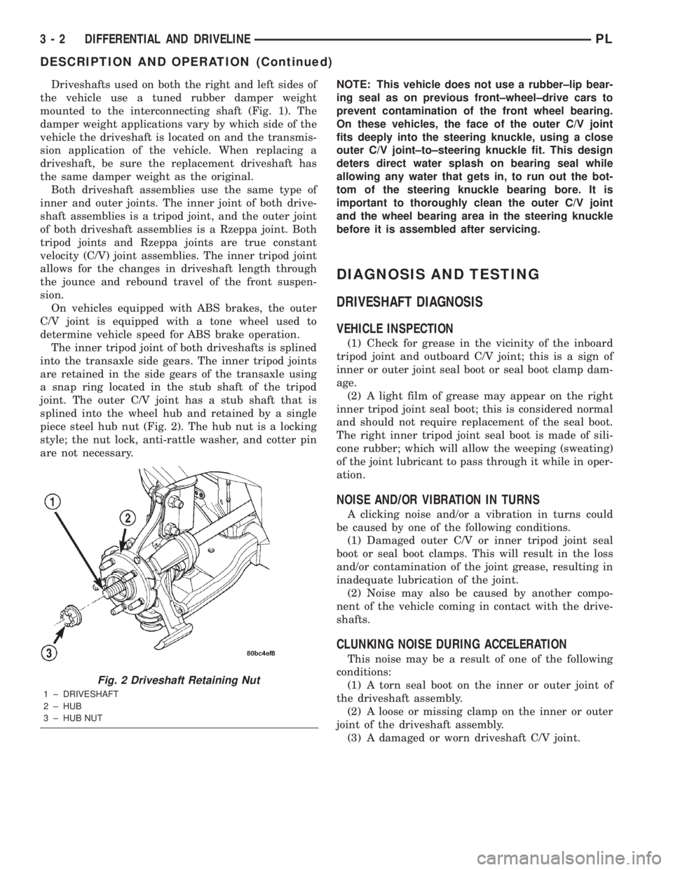
piece steel hub nut (Fig. 2). The hub nut is a locking
style; the nut lock, anti-rattle washer, and cotter pin
are not necessary.NOTE: This vehicle does not use a rubber±lip bear-
ing seal as on previous front±wheel±drive cars to
prevent contamination of the front wheel bearing.
On these vehicles, the face of the outer C/V joint
fits deeply into the steering knuckle, using a close
outer C/V joint±to±steering knuckle fit. This design
deters direct water splash on bearing seal while
allowing any water that gets in, to run out the bot-
tom of the steering knuckle bearing bore. It is
important to thoroughly clean the outer C/V joint
and the wheel bearing area in the steering knuckle
before it is assembled after servicing.
DIAGNOSIS AND TESTING
DRIVESHAFT DIAGNOSIS
VEHICLE INSPECTION
(1) Check for grease in the vicinity of the inboard
tripod joint and outboard C/V joint; this is a sign of
inner or outer joint seal boot or seal boot clamp dam-
age.
(2) A light film of grease may appear on the right
inner tripod joint seal boot; this is considered normal
and should not require replacement of the seal boot.
The right inner tripod joint seal boot is made of sili-
cone rubber; which will allow the weeping (sweating)
of the joint lubricant to pass through it while in oper-
ation.
NOISE AND/OR VIBRATION IN TURNS
A clicking noise and/or a vibration in turns could
be caused by one of the following conditions.
(1) Damaged outer C/V or inner tripod joint seal
boot or seal boot clamps. This will result in the loss
and/or contamination of the joint grease, resulting in
inadequate lubrication of the joint.
(2) Noise may also be caused by another compo-
nent of the vehicle coming in contact with the drive-
shafts.
CLUNKING NOISE DURING ACCELERATION
This noise may be a result of one of the following
conditions:
(1) A torn seal boot on the inner or outer joint of
the driveshaft assembly.
(2) A loose or missing clamp on the inner or outer
joint of the driveshaft assembly.
(3) A damaged or worn driveshaft C/V joint.
Fig. 2 Driveshaft Retaining Nut
1 ± DRIVESHAFT
2 ± HUB
3 ± HUB NUT
3 - 2 DIFFERENTIAL AND DRIVELINEPL
DESCRIPTION AND OPERATION (Continued)
Page 83 of 1285
Proportioning valves balance front to rear braking
by controlling the brake fluid hydraulic pressure to
the rear brakes. Under light pedal application, the
proportioning valve allows normal fluid flow to the
rear brakes. Under higher pedal effort, the valve
reduces fluid pressure to the rear brakes.
The non-antilock master cylinder is a four-outlet
design with two screw-in proportioning valves
attached directly to the master cylinder housing (Fig.
3). One proportioning valve controls each rear brake.
BRAKE TUBES AND HOSES
The purpose of the brake tubes and flex hoses is to
transfer the pressurized brake fluid developed by the
master cylinder to the brakes at each wheel of the
vehicle. The flex hoses connect the chassis brake
tubes, which are mounted to the vehicle's underbody,
to the brake at each wheel, allowing for movement of
the vehicle's suspension. The brake tubes are steel
with a corrosion-resistant nylon coating applied to
the external surfaces. The flex hoses are made of
reinforced rubber.
DISC BRAKES (FRONT)
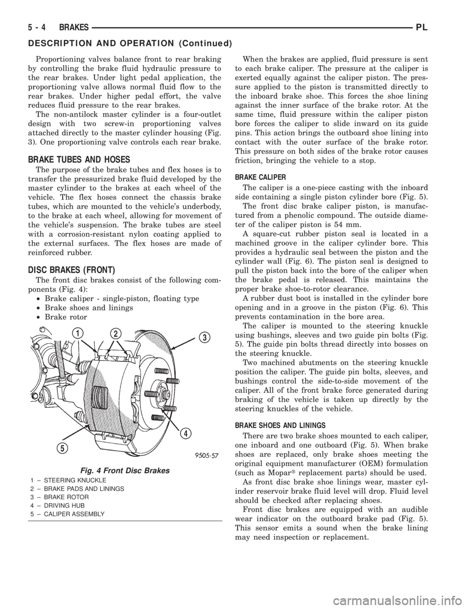
The front disc brakes consist of the following com-
ponents (Fig. 4):
²Brake caliper - single-piston, floating type
²Brake shoes and linings
²Brake rotorWhen the brakes are applied, fluid pressure is sent
to each brake caliper. The pressure at the caliper is
exerted equally against the caliper piston. The pres-
sure applied to the piston is transmitted directly to
the inboard brake shoe. This forces the shoe lining
against the inner surface of the brake rotor. At the
same time, fluid pressure within the caliper piston
bore forces the caliper to slide inward on its guide
pins. This action brings the outboard shoe lining into
contact with the outer surface of the brake rotor.
This pressure on both sides of the brake rotor causes
friction, bringing the vehicle to a stop.
BRAKE CALIPER
The caliper is a one-piece casting with the inboard
side containing a single piston cylinder bore (Fig. 5).
The front disc brake caliper piston, is manufac-
tured from a phenolic compound. The outside diame-
ter of the caliper piston is 54 mm.
A square-cut rubber piston seal is located in a
machined groove in the caliper cylinder bore. This
provides a hydraulic seal between the piston and the
cylinder wall (Fig. 6). The piston seal is designed to
pull the piston back into the bore of the caliper when
the brake pedal is released. This maintains the
proper brake shoe-to-rotor clearance.
A rubber dust boot is installed in the cylinder bore
opening and in a groove in the piston (Fig. 6). This
prevents contamination in the bore area.
The caliper is mounted to the steering knuckle
using bushings, sleeves and two guide pin bolts (Fig.
5). The guide pin bolts thread directly into bosses on
the steering knuckle.
Two machined abutments on the steering knuckle
position the caliper. The guide pin bolts, sleeves, and
bushings control the side-to-side movement of the
caliper. All of the front brake force generated during
braking of the vehicle is taken up directly by the
steering knuckles of the vehicle.
BRAKE SHOES AND LININGS
There are two brake shoes mounted to each caliper,
one inboard and one outboard (Fig. 5). When brake
shoes are replaced, only brake shoes meeting the
original equipment manufacturer (OEM) formulation
(such as Mopartreplacement parts) should be used.
As front disc brake shoe linings wear, master cyl-
inder reservoir brake fluid level will drop. Fluid level
should be checked after replacing shoes.
Front disc brakes are equipped with an audible
wear indicator on the outboard brake pad (Fig. 5).
This sensor emits a sound when the brake lining
may need inspection or replacement.
Fig. 4 Front Disc Brakes
1 ± STEERING KNUCKLE
2 ± BRAKE PADS AND LININGS
3 ± BRAKE ROTOR
4 ± DRIVING HUB
5 ± CALIPER ASSEMBLY
5 - 4 BRAKESPL
DESCRIPTION AND OPERATION (Continued)
Page 88 of 1285
DIAGNOSIS AND TESTING
BASE BRAKE SYSTEM DIAGNOSIS CHARTS
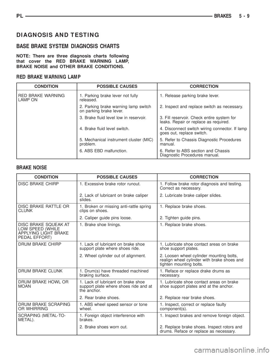
NOTE: There are three diagnosis charts following
that cover the RED BRAKE WARNING LAMP,
BRAKE NOISE and OTHER BRAKE CONDITIONS.
RED BRAKE WARNING LAMP
CONDITION POSSIBLE CAUSES CORRECTION
RED BRAKE WARNING
LAMP ON1. Parking brake lever not fully
released.1. Release parking brake lever.
2. Parking brake warning lamp switch
on parking brake lever.2. Inspect and replace switch as necessary.
3. Brake fluid level low in reservoir. 3. Fill reservoir. Check entire system for
leaks. Repair or replace as required.
4. Brake fluid level switch. 4. Disconnect switch wiring connector. If lamp
goes out, replace switch.
5. Mechanical instrument cluster (MIC)
problem.5. Refer to Chassis Diagnostic Procedures
manual.
6. ABS EBD malfunction. 6. Refer to ABS section and Chassis
Diagnostic Procedures manual.
BRAKE NOISE
CONDITION POSSIBLE CAUSES CORRECTION
DISC BRAKE CHIRP 1. Excessive brake rotor runout. 1. Follow brake rotor diagnosis and testing.
Correct as necessary.
2. Lack of lubricant on brake caliper
slides.2. Lubricate brake caliper slides.
DISC BRAKE RATTLE OR
CLUNK1. Broken or missing anti-rattle spring
clips on shoes.1. Replace brake shoes.
2. Caliper guide pins loose. 2. Tighten guide pins.
DISC BRAKE SQUEAK AT
LOW SPEED (WHILE
APPLYING LIGHT BRAKE
PEDAL EFFORT)1. Brake shoe linings. 1. Replace brake shoes.
DRUM BRAKE CHIRP 1. Lack of lubricant on brake shoe
support plate where shoes ride.1. Lubricate shoe contact areas on brake
shoe support plates.
2. Wheel cylinder out of alignment. 2. Loosen wheel cylinder mounting bolts,
realign wheel cylinder with brake shoes and
tighten mounting bolts.
DRUM BRAKE CLUNK 1. Drum(s) have threaded machined
braking surface.1. Reface or replace drake drums as
necessary.
DRUM BRAKE HOWL OR
MOAN1. Lack of lubricant on brake shoe
support plate where shoes ride and at
the anchor.1. Lubricate shoe contact areas on brake
shoe support plates and at the anchor.
2. Rear brake shoes. 2. Replace rear brake shoes.
DRUM BRAKE SCRAPING
OR WHIRRING1. ABS wheel speed sensor or tone
wheel.1. Inspect, correct or replace faulty
component(s).
SCRAPING (METAL-TO-
METAL).1. Foreign object interference with
brakes.1. Inspect brakes and remove foreign object.
2. Brake shoes worn out. 2. Replace brake shoes. Inspect rotors and
drums. Reface or replace as necessary.
PLBRAKES 5 - 9
Page 90 of 1285
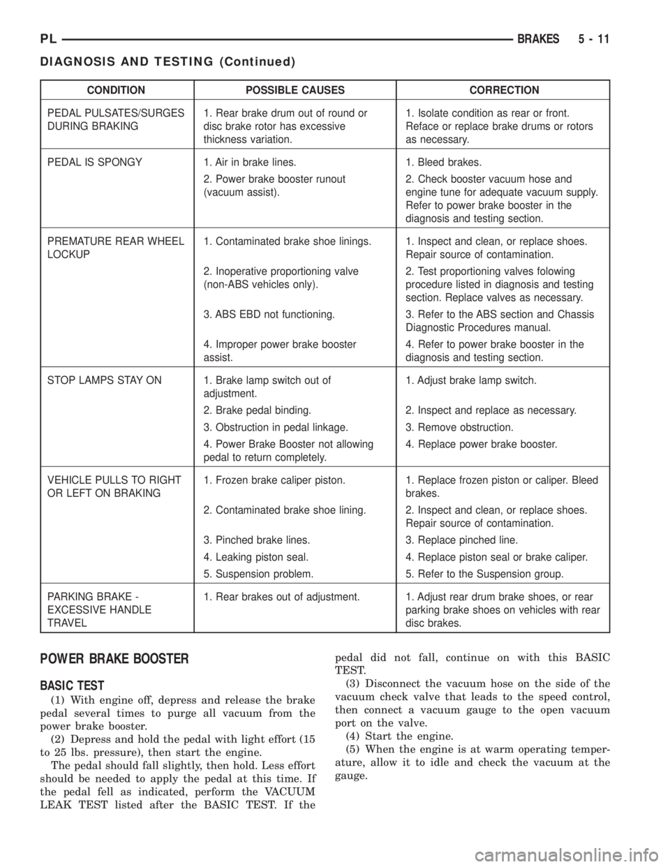
CONDITION POSSIBLE CAUSES CORRECTION
PEDAL PULSATES/SURGES
DURING BRAKING1. Rear brake drum out of round or
disc brake rotor has excessive
thickness variation.1. Isolate condition as rear or front.
Reface or replace brake drums or rotors
as necessary.
PEDAL IS SPONGY 1. Air in brake lines. 1. Bleed brakes.
2. Power brake booster runout
(vacuum assist).2. Check booster vacuum hose and
engine tune for adequate vacuum supply.
Refer to power brake booster in the
diagnosis and testing section.
PREMATURE REAR WHEEL
LOCKUP1. Contaminated brake shoe linings. 1. Inspect and clean, or replace shoes.
Repair source of contamination.
2. Inoperative proportioning valve
(non-ABS vehicles only).2. Test proportioning valves folowing
procedure listed in diagnosis and testing
section. Replace valves as necessary.
3. ABS EBD not functioning. 3. Refer to the ABS section and Chassis
Diagnostic Procedures manual.
4. Improper power brake booster
assist.4. Refer to power brake booster in the
diagnosis and testing section.
STOP LAMPS STAY ON 1. Brake lamp switch out of
adjustment.1. Adjust brake lamp switch.
2. Brake pedal binding. 2. Inspect and replace as necessary.
3. Obstruction in pedal linkage. 3. Remove obstruction.
4. Power Brake Booster not allowing
pedal to return completely.4. Replace power brake booster.
VEHICLE PULLS TO RIGHT
OR LEFT ON BRAKING1. Frozen brake caliper piston. 1. Replace frozen piston or caliper. Bleed
brakes.
2. Contaminated brake shoe lining. 2. Inspect and clean, or replace shoes.
Repair source of contamination.
3. Pinched brake lines. 3. Replace pinched line.
4. Leaking piston seal. 4. Replace piston seal or brake caliper.
5. Suspension problem. 5. Refer to the Suspension group.
PARKING BRAKE -
EXCESSIVE HANDLE
TRAVEL1. Rear brakes out of adjustment. 1. Adjust rear drum brake shoes, or rear
parking brake shoes on vehicles with rear
disc brakes.
POWER BRAKE BOOSTER
BASIC TEST
(1) With engine off, depress and release the brake
pedal several times to purge all vacuum from the
power brake booster.
(2) Depress and hold the pedal with light effort (15
to 25 lbs. pressure), then start the engine.
The pedal should fall slightly, then hold. Less effort
should be needed to apply the pedal at this time. If
the pedal fell as indicated, perform the VACUUM
LEAK TEST listed after the BASIC TEST. If thepedal did not fall, continue on with this BASIC
TEST.
(3) Disconnect the vacuum hose on the side of the
vacuum check valve that leads to the speed control,
then connect a vacuum gauge to the open vacuum
port on the valve.
(4) Start the engine.
(5) When the engine is at warm operating temper-
ature, allow it to idle and check the vacuum at the
gauge.
PLBRAKES 5 - 11
DIAGNOSIS AND TESTING (Continued)
Page 91 of 1285
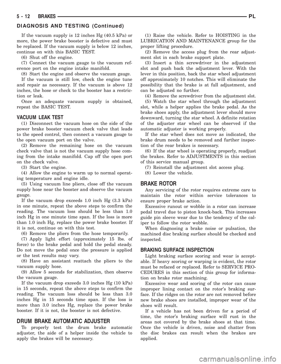
If the vacuum supply is 12 inches Hg (40.5 kPa) or
more, the power brake booster is defective and must
be replaced. If the vacuum supply is below 12 inches,
continue on with this BASIC TEST.
(6) Shut off the engine.
(7) Connect the vacuum gauge to the vacuum ref-
erence port on the engine intake manifold.
(8)
Start the engine and observe the vacuum gauge.
If the vacuum is still low, check the engine tune
and repair as necessary. If the vacuum is above 12
inches, the hose or check to the booster has a restric-
tion or leak.
Once an adequate vacuum supply is obtained,
repeat the BASIC TEST.
VACUUM LEAK TEST
(1) Disconnect the vacuum hose on the side of the
power brake booster vacuum check valve that leads
to the speed control, then connect a vacuum gauge to
the open vacuum port on the valve.
(2) Remove the remaining hose on the vacuum
check valve that is not the vacuum supply hose com-
ing from the intake manifold. Cap off the open port
on the check valve.
(3) Start the engine.
(4) Allow the engine to warm up to normal operat-
ing temperature and engine idle.
(5) Using vacuum line pliers, close off the vacuum
supply hose near the booster and observe the vacuum
gauge.
If the vacuum drop exceeds 1.0 inch Hg (3.3 kPa)
in one minute, repeat the above steps to confirm the
reading. The vacuum loss should be less than 1.0
inch Hg in one minute time span. If the loss is more
than 1.0 inch Hg, replace the power brake booster. If
it is not, continue on with this test.
(6) Remove the pliers from the hose temporarily.
(7) Apply light effort (approximately 15 lbs. of
force) to the brake pedal and hold the pedal steady.
Do not move the pedal once the pressure is applied
or the test results may vary.
(8) Have an assistant reattach the pliers to the
vacuum supply hose.
(9) Allow 5 seconds for stabilization, then observe
the vacuum gauge.
If the vacuum drop exceeds 3.0 inches Hg (10 kPa)
in 15 seconds, repeat the above steps to confirm the
reading. The vacuum loss should be less than 3.0
inches Hg in 15 seconds time span. If the loss is
more than 3.0 inches Hg, replace the power brake
booster. If it is not, the booster is not defective.
DRUM BRAKE AUTOMATIC ADJUSTER
To properly test the drum brake automatic
adjuster, the aide of a helper inside the vehicle to
apply the brakes will be necessary.(1) Raise the vehicle. Refer to HOISTING in the
LUBRICATION AND MAINTENANCE group for the
proper lifting procedure.
(2) Remove the access plug from the rear adjust-
ment slot in each brake support plate.
(3) Insert a thin screwdriver in the adjustment
slot and push back the adjustment lever. With the
lever in this position, back the star wheel adjustment
off approximately 10 notches. This will eliminate the
possibility that the brake is at full adjustment, and
can be adjusted no further.
(4)
Remove the screwdriver from the adjustment slot.
(5) Watch the star wheel through the adjustment
slot, while a helper applies the brake pedal. As the
brake shoes apply, the adjustment lever should move
downward, turning the star wheel. A definite rotation
of the adjuster star wheel can be observed if the
automatic adjuster is working properly.
If the star wheel does not move as indicated, the
brake drum needs to be removed and further inspec-
tion of the rear brakes is necessary.
(6) If the star wheel is operating properly, readjust
the brakes. Refer to ADJUSTMENTS in this section
of this service manual group.
(7) Reinstall the adjustment slot access plug.
(8) Lower the vehicle.
BRAKE ROTOR
Any servicing of the rotor requires extreme care to
maintain the rotor within service tolerances to
ensure proper brake action.
Excessive runout or wobble in a rotor can increase
pedal travel due to piston knock-back. This increases
guide pin sleeve wear due to the tendency of the cal-
iper to follow the rotor wobble.
When diagnosing a brake noise or pulsation, the
machined disc braking surface should be checked and
inspected.
BRAKING SURFACE INSPECTION
Light braking surface scoring and wear is accept-
able. If heavy scoring or warping is evident, the rotor
must be refaced or replaced. Refer to SERVICE PRO-
CEDURES in this section of this group for informa-
tion on brake rotor machining.
Excessive wear and scoring of the rotor can cause
improper lining contact on the rotor's braking sur-
face. If the ridges on the rotor are not removed before
new brake shoes are installed, improper wear of the
shoes will result.
If a vehicle has not been driven for a period of
time, the rotor's braking surface will rust in the
areas not covered by the brake shoes at that time.
Once the vehicle is driven, noise and chatter from
the disc brakes can result when the brakes are
applied.
5 - 12 BRAKESPL
DIAGNOSIS AND TESTING (Continued)
Page 124 of 1285
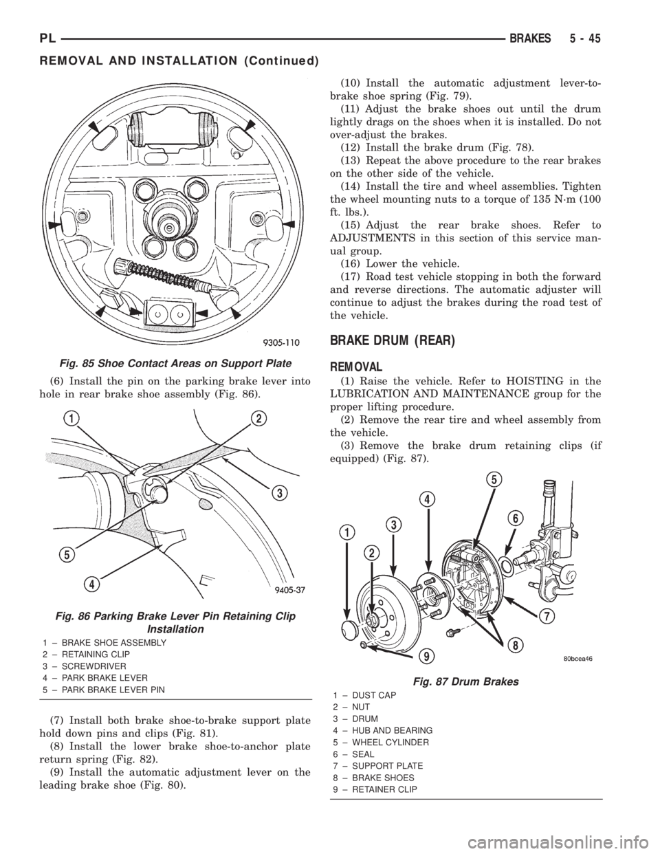
(6) Install the pin on the parking brake lever into
hole in rear brake shoe assembly (Fig. 86).
(7) Install both brake shoe-to-brake support plate
hold down pins and clips (Fig. 81).
(8) Install the lower brake shoe-to-anchor plate
return spring (Fig. 82).
(9) Install the automatic adjustment lever on the
leading brake shoe (Fig. 80).(10) Install the automatic adjustment lever-to-
brake shoe spring (Fig. 79).
(11) Adjust the brake shoes out until the drum
lightly drags on the shoes when it is installed. Do not
over-adjust the brakes.
(12) Install the brake drum (Fig. 78).
(13) Repeat the above procedure to the rear brakes
on the other side of the vehicle.
(14) Install the tire and wheel assemblies. Tighten
the wheel mounting nuts to a torque of 135 N´m (100
ft. lbs.).
(15) Adjust the rear brake shoes. Refer to
ADJUSTMENTS in this section of this service man-
ual group.
(16) Lower the vehicle.
(17) Road test vehicle stopping in both the forward
and reverse directions. The automatic adjuster will
continue to adjust the brakes during the road test of
the vehicle.
BRAKE DRUM (REAR)
REMOVAL
(1) Raise the vehicle. Refer to HOISTING in the
LUBRICATION AND MAINTENANCE group for the
proper lifting procedure.
(2) Remove the rear tire and wheel assembly from
the vehicle.
(3) Remove the brake drum retaining clips (if
equipped) (Fig. 87).
Fig. 85 Shoe Contact Areas on Support Plate
Fig. 86 Parking Brake Lever Pin Retaining Clip
Installation
1 ± BRAKE SHOE ASSEMBLY
2 ± RETAINING CLIP
3 ± SCREWDRIVER
4 ± PARK BRAKE LEVER
5 ± PARK BRAKE LEVER PIN
Fig. 87 Drum Brakes
1 ± DUST CAP
2 ± NUT
3 ± DRUM
4 ± HUB AND BEARING
5 ± WHEEL CYLINDER
6 ± SEAL
7 ± SUPPORT PLATE
8 ± BRAKE SHOES
9 ± RETAINER CLIP
PLBRAKES 5 - 45
REMOVAL AND INSTALLATION (Continued)
Page 136 of 1285
CALIPER PISTON AND SEALS
CALIPER PISTON REMOVAL
WARNING: UNDER NO CONDITION SHOULD HIGH
PRESSURE AIR EVER BE USED TO REMOVE A PIS-
TON FROM A CALIPER BORE. PERSONAL INJURY
COULD RESULT FROM SUCH A PRACTICE.
NOTE: The safest way to remove the piston from
the caliper bore is to use the hydraulic pressure of
the vehicle's brake system.
(1) Following the removal procedure in DISC
BRAKE SHOES found in this section, remove the
caliper from the brake rotor and hang the assembly
on a wire hook away from rotor and body of the vehi-
cle so brake fluid cannot get on these components.
Remove the brake shoes, and place a small piece of
wood between the piston and caliper fingers.
(2) Carefully depress the brake pedal to hydrauli-
cally push piston out of its bore. Once completed,
apply and hold down the brake pedal to any position
beyond the first inch of pedal travel using a brake
pedal holding tool. This will prevent the fluid in the
master cylinder reservoir from completely draining
out.(3) Disconnect the brake fluid flex hose from the
caliper assembly and remove it from the vehicle.
CALIPER SEAL REMOVAL
CAUTION: Do not use excessive force when clamp-
ing caliper in vise. Excessive vise pressure will
cause bore distortion.
(1) To disassemble the caliper, mount it in a vise
equipped with protective jaws.
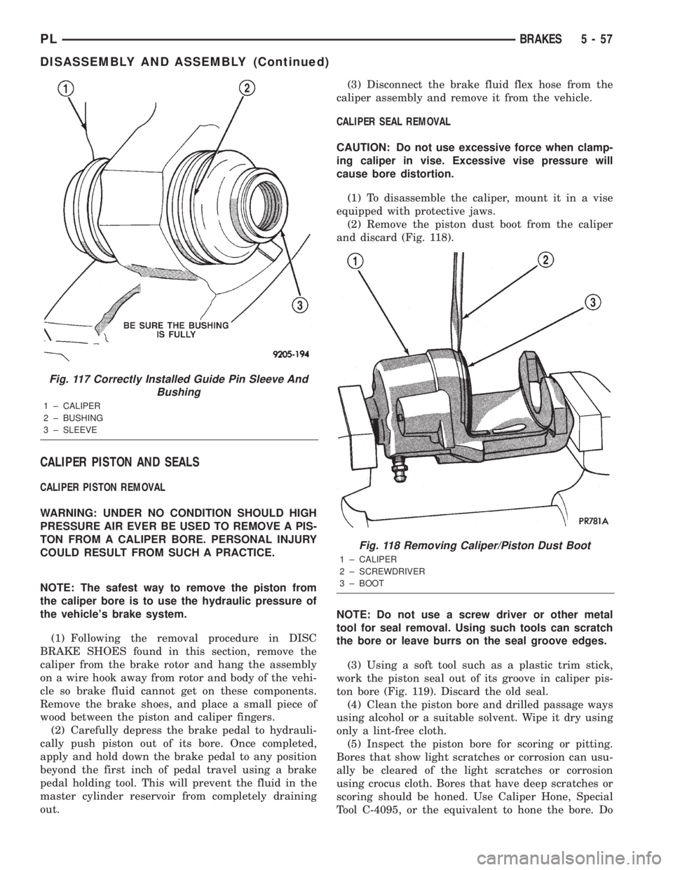
(2) Remove the piston dust boot from the caliper
and discard (Fig. 118).
NOTE: Do not use a screw driver or other metal
tool for seal removal. Using such tools can scratch
the bore or leave burrs on the seal groove edges.
(3) Using a soft tool such as a plastic trim stick,
work the piston seal out of its groove in caliper pis-
ton bore (Fig. 119). Discard the old seal.
(4) Clean the piston bore and drilled passage ways
using alcohol or a suitable solvent. Wipe it dry using
only a lint-free cloth.
(5) Inspect the piston bore for scoring or pitting.
Bores that show light scratches or corrosion can usu-
ally be cleared of the light scratches or corrosion
using crocus cloth. Bores that have deep scratches or
scoring should be honed. Use Caliper Hone, Special
Tool C-4095, or the equivalent to hone the bore. Do
Fig. 117 Correctly Installed Guide Pin Sleeve And
Bushing
1 ± CALIPER
2 ± BUSHING
3 ± SLEEVE
Fig. 118 Removing Caliper/Piston Dust Boot
1 ± CALIPER
2 ± SCREWDRIVER
3 ± BOOT
PLBRAKES 5 - 57
DISASSEMBLY AND ASSEMBLY (Continued)