2000 DODGE NEON stop start
[x] Cancel search: stop startPage 9 of 1285
onds, stop cranking engine and allow starter to cool
(15 minutes), before cranking again.
DISCONNECT CABLE CLAMPS AS FOLLOWS:
²Disconnect BLACK cable clamp from engine
ground on disabled vehicle.
²When using a Booster vehicle, disconnect
BLACK cable clamp from battery negative terminal.
Disconnect RED cable clamp from battery positive
terminal.
²Disconnect RED cable clamp from battery posi-
tive terminal on disabled vehicle.
TOWING RECOMMENDATIONS
WARNING: DO NOT ALLOW TOWING ATTACHMENT
DEVICES TO CONTACT THE FUEL TANK OR LINES,
FUEL LEAK CAN RESULT. DO NOT LIFT OR TOW
VEHICLE BY FRONT OR REAR BUMPER, OR
BUMPER ENERGY ABSORBER UNITS. DO NOT
VENTURE UNDER A LIFTED VEHICLE IF NOT SUP-
PORTED PROPERLY ON SAFETY STANDS. DO NOT
ALLOW PASSENGERS TO RIDE IN A TOWED VEHI-
CLE. USE A SAFETY CHAIN THAT IS INDEPENDENT
FROM THE TOWING ATTACHMENT DEVICE.
CAUTION: Do not damage brake lines, exhaust sys-
tem, shock absorbers, sway bars, or any other
under vehicle components when attaching towing
device to vehicle. Do not attach towing device to
front or rear suspension components. Do notsecure vehicle to towing device by the use of front
or rear suspension or steering components.
Remove or secure loose or protruding objects from
a damaged vehicle before towing. Refer to state and
local rules and regulations before towing a vehicle.
Do not allow weight of towed vehicle to bear on
lower fascia, air dams, or spoilers.
RECOMMENDED TOWING EQUIPMENT
To avoid damage to bumper fascia and air dams
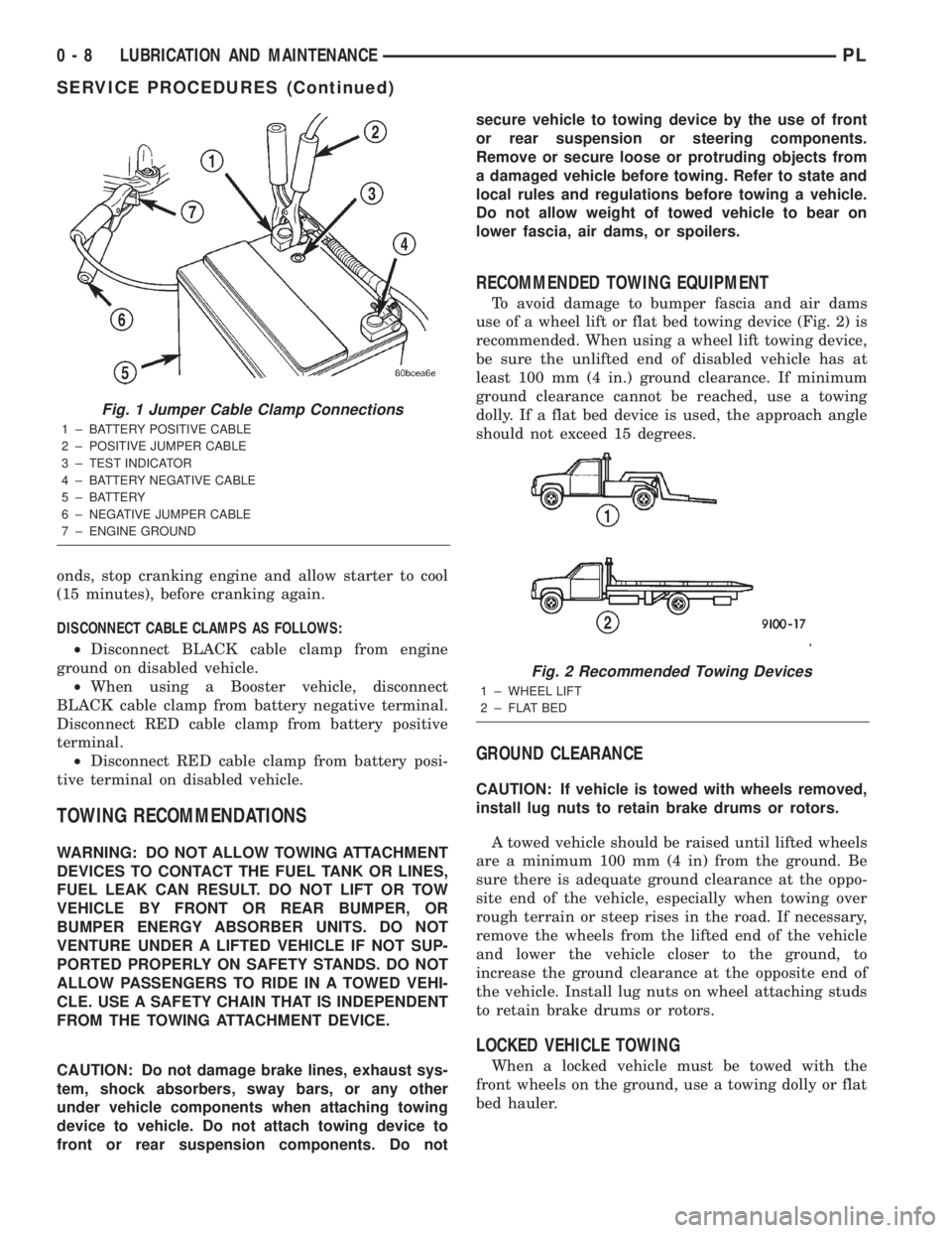
use of a wheel lift or flat bed towing device (Fig. 2) is
recommended. When using a wheel lift towing device,
be sure the unlifted end of disabled vehicle has at
least 100 mm (4 in.) ground clearance. If minimum
ground clearance cannot be reached, use a towing
dolly. If a flat bed device is used, the approach angle
should not exceed 15 degrees.
GROUND CLEARANCE
CAUTION: If vehicle is towed with wheels removed,
install lug nuts to retain brake drums or rotors.
A towed vehicle should be raised until lifted wheels
are a minimum 100 mm (4 in) from the ground. Be
sure there is adequate ground clearance at the oppo-
site end of the vehicle, especially when towing over
rough terrain or steep rises in the road. If necessary,
remove the wheels from the lifted end of the vehicle
and lower the vehicle closer to the ground, to
increase the ground clearance at the opposite end of
the vehicle. Install lug nuts on wheel attaching studs
to retain brake drums or rotors.
LOCKED VEHICLE TOWING
When a locked vehicle must be towed with the
front wheels on the ground, use a towing dolly or flat
bed hauler.
Fig. 1 Jumper Cable Clamp Connections
1 ± BATTERY POSITIVE CABLE
2 ± POSITIVE JUMPER CABLE
3 ± TEST INDICATOR
4 ± BATTERY NEGATIVE CABLE
5 ± BATTERY
6 ± NEGATIVE JUMPER CABLE
7 ± ENGINE GROUND
Fig. 2 Recommended Towing Devices
1 ± WHEEL LIFT
2 ± FLAT BED
0 - 8 LUBRICATION AND MAINTENANCEPL
SERVICE PROCEDURES (Continued)
Page 90 of 1285
CONDITION POSSIBLE CAUSES CORRECTION
PEDAL PULSATES/SURGES
DURING BRAKING1. Rear brake drum out of round or
disc brake rotor has excessive
thickness variation.1. Isolate condition as rear or front.
Reface or replace brake drums or rotors
as necessary.
PEDAL IS SPONGY 1. Air in brake lines. 1. Bleed brakes.
2. Power brake booster runout
(vacuum assist).2. Check booster vacuum hose and
engine tune for adequate vacuum supply.
Refer to power brake booster in the
diagnosis and testing section.
PREMATURE REAR WHEEL
LOCKUP1. Contaminated brake shoe linings. 1. Inspect and clean, or replace shoes.
Repair source of contamination.
2. Inoperative proportioning valve
(non-ABS vehicles only).2. Test proportioning valves folowing
procedure listed in diagnosis and testing
section. Replace valves as necessary.
3. ABS EBD not functioning. 3. Refer to the ABS section and Chassis
Diagnostic Procedures manual.
4. Improper power brake booster
assist.4. Refer to power brake booster in the
diagnosis and testing section.
STOP LAMPS STAY ON 1. Brake lamp switch out of
adjustment.1. Adjust brake lamp switch.
2. Brake pedal binding. 2. Inspect and replace as necessary.
3. Obstruction in pedal linkage. 3. Remove obstruction.
4. Power Brake Booster not allowing
pedal to return completely.4. Replace power brake booster.
VEHICLE PULLS TO RIGHT
OR LEFT ON BRAKING1. Frozen brake caliper piston. 1. Replace frozen piston or caliper. Bleed
brakes.
2. Contaminated brake shoe lining. 2. Inspect and clean, or replace shoes.
Repair source of contamination.
3. Pinched brake lines. 3. Replace pinched line.
4. Leaking piston seal. 4. Replace piston seal or brake caliper.
5. Suspension problem. 5. Refer to the Suspension group.
PARKING BRAKE -
EXCESSIVE HANDLE
TRAVEL1. Rear brakes out of adjustment. 1. Adjust rear drum brake shoes, or rear
parking brake shoes on vehicles with rear
disc brakes.
POWER BRAKE BOOSTER
BASIC TEST
(1) With engine off, depress and release the brake
pedal several times to purge all vacuum from the
power brake booster.
(2) Depress and hold the pedal with light effort (15
to 25 lbs. pressure), then start the engine.
The pedal should fall slightly, then hold. Less effort
should be needed to apply the pedal at this time. If
the pedal fell as indicated, perform the VACUUM
LEAK TEST listed after the BASIC TEST. If thepedal did not fall, continue on with this BASIC
TEST.
(3) Disconnect the vacuum hose on the side of the
vacuum check valve that leads to the speed control,
then connect a vacuum gauge to the open vacuum
port on the valve.
(4) Start the engine.
(5) When the engine is at warm operating temper-
ature, allow it to idle and check the vacuum at the
gauge.
PLBRAKES 5 - 11
DIAGNOSIS AND TESTING (Continued)
Page 118 of 1285
(1) Completely retract the caliper piston back into
piston bore of the caliper.
(2) Lubricate both adapter caliper slide abutments
with a liberal amount of MopartMultipurpose Lubri-
cant, or an equivalent.
CAUTION: Use care when installing the caliper
assembly onto adapter so the guide pin bushings
and sleeves do not get damaged by the mounting
bosses on adapter.
(3) Starting with the lower end, carefully lower the
caliper and brake shoes over the brake rotor and
catch the caliper's bottom edge behind the caliper
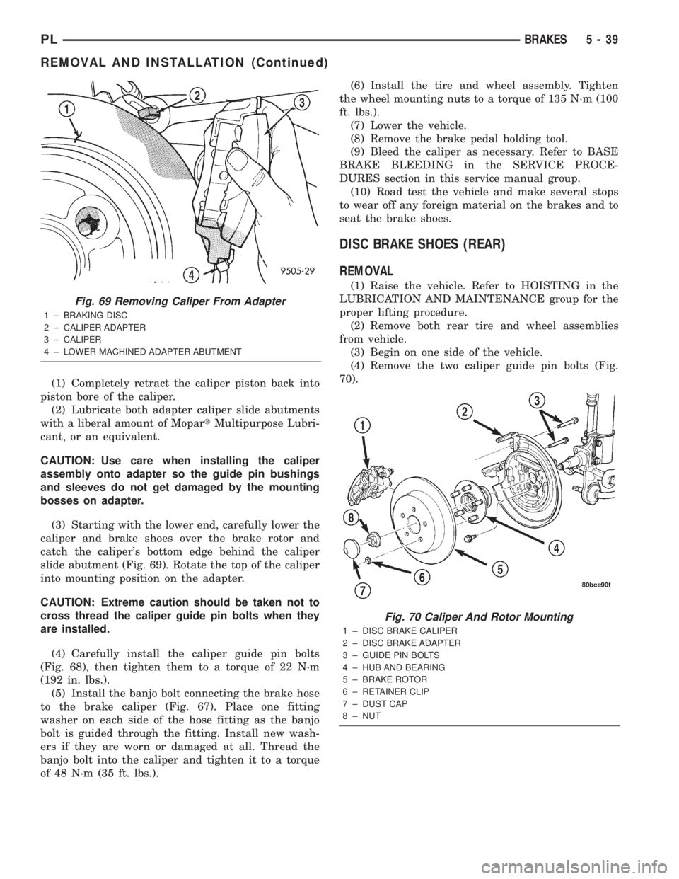
slide abutment (Fig. 69). Rotate the top of the caliper
into mounting position on the adapter.
CAUTION: Extreme caution should be taken not to
cross thread the caliper guide pin bolts when they
are installed.
(4) Carefully install the caliper guide pin bolts
(Fig. 68), then tighten them to a torque of 22 N´m
(192 in. lbs.).
(5) Install the banjo bolt connecting the brake hose
to the brake caliper (Fig. 67). Place one fitting
washer on each side of the hose fitting as the banjo
bolt is guided through the fitting. Install new wash-
ers if they are worn or damaged at all. Thread the
banjo bolt into the caliper and tighten it to a torque
of 48 N´m (35 ft. lbs.).(6) Install the tire and wheel assembly. Tighten
the wheel mounting nuts to a torque of 135 N´m (100
ft. lbs.).
(7) Lower the vehicle.
(8) Remove the brake pedal holding tool.
(9) Bleed the caliper as necessary. Refer to BASE
BRAKE BLEEDING in the SERVICE PROCE-
DURES section in this service manual group.
(10) Road test the vehicle and make several stops
to wear off any foreign material on the brakes and to
seat the brake shoes.
DISC BRAKE SHOES (REAR)
REMOVAL
(1) Raise the vehicle. Refer to HOISTING in the
LUBRICATION AND MAINTENANCE group for the
proper lifting procedure.
(2) Remove both rear tire and wheel assemblies
from vehicle.
(3) Begin on one side of the vehicle.
(4) Remove the two caliper guide pin bolts (Fig.
70).
Fig. 69 Removing Caliper From Adapter
1 ± BRAKING DISC
2 ± CALIPER ADAPTER
3 ± CALIPER
4 ± LOWER MACHINED ADAPTER ABUTMENT
Fig. 70 Caliper And Rotor Mounting
1 ± DISC BRAKE CALIPER
2 ± DISC BRAKE ADAPTER
3 ± GUIDE PIN BOLTS
4 ± HUB AND BEARING
5 ± BRAKE ROTOR
6 ± RETAINER CLIP
7 ± DUST CAP
8 ± NUT
PLBRAKES 5 - 39
REMOVAL AND INSTALLATION (Continued)
Page 120 of 1285
(6) Lubricate both adapter caliper slide abutments
with a liberal amount of MopartMultipurpose Lubri-
cant, or an equivalent.
CAUTION: Use care when installing the caliper
assembly onto adapter so the guide pin bushings
and sleeves do not get damaged by the mounting
bosses on adapter.
(7) Starting with the lower end, carefully lower the
caliper and brake shoes over the brake rotor and
catch the caliper's bottom edge behind the caliper
slide abutment (Fig. 71). Rotate the top of the caliper
into mounting position on the adapter.
CAUTION: Extreme caution should be taken not to
cross thread the caliper guide pin bolts when they
are installed.
(8) Carefully install the caliper guide pin bolts
(Fig. 70), then tighten them to a torque of 22 N´m
(192 in. lbs.).
(9) Install the tire and wheel assembly. Tighten
the wheel mounting nuts to a torque of 135 N´m (100
ft. lbs.).
(10) Repeat the above procedure to the rear brakes
on the other side of the vehicle.
(11) Lower the vehicle.
(12) Pump the brake pedal several times to ensure
the vehicle has a firm brake pedal before moving the
vehicle.(13) Road test the vehicle and make several stops
to wear off any foreign material on the brakes and to
seat the brake shoes.
BRAKE ROTOR (REAR)
REMOVAL
(1) Raise the vehicle. Refer to HOISTING in the
LUBRICATION AND MAINTENANCE group for the
proper lifting procedure.
(2) Remove the rear tire and wheel assembly.
(3) Remove the rear disc brake caliper assembly
from the brake rotor and store it out of the way.
Refer to DISC BRAKE SHOES (REAR) in this
REMOVAL AND INSTALLATION section of this ser-
vice manual group.
(4) Remove any clips retaining the brake rotor
(Fig. 70).
(5) Remove the brake rotor by pulling it straight
off the wheel mounting studs.
INSTALLATION
NOTE: Inspect the disc brake shoes and parking
brake shoes before brake rotor installation.
(1) Install the rear brake rotor over the wheel
mounting studs and onto the hub (Fig. 70).
(2) Install rear disc brake caliper. Refer to DISC
BRAKE SHOES (REAR) in this REMOVAL AND
INSTALLATION section of this service manual
group.
(3) Install the tire and wheel assembly. Tighten
the wheel mounting nuts to a torque of 135 N´m (100
ft. lbs.).
(4) Adjust the parking brake shoes as necessary.
Refer to ADJUSTMENTS in this section of this ser-
vice manual group.
(5) Lower the vehicle.
(6) Pump the brake pedal before moving the vehi-
cle to set the brake shoes to the brake rotor.
DRUM BRAKE WHEEL CYLINDER (REAR)
NOTE: Before proceeding with this procedure,
review SERVICE WARNINGS AND CAUTIONS at the
beginning of REMOVAL AND INSTALLATION in this
section.
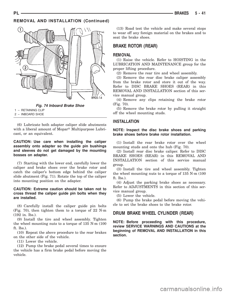
Fig. 74 Inboard Brake Shoe
1 ± RETAINING CLIP
2 ± INBOARD SHOE
PLBRAKES 5 - 41
REMOVAL AND INSTALLATION (Continued)
Page 145 of 1285
NOISE AND BRAKE PEDAL FEEL
During ABS braking, some brake pedal movement
may be felt. In addition, ABS braking will create
ticking, popping, or groaning noises heard by the
driver. This is normal and is due to pressurized fluid
being transferred between the master cylinder and
the brakes. If ABS operation occurs during hard
braking, some pulsation may be felt in the vehicle
body due to fore-and-aft movement of the suspension
as brake pressures are modulated.
At the end of an ABS stop, ABS is turned off when
the vehicle is slowed to a speed of 3±4 mph. There
may be a slight brake pedal drop anytime that the
ABS is deactivated, such as at the end of the stop
when the vehicle speed is less than 3 mph or during
an ABS stop where ABS is no longer required. These
conditions exist when a vehicle is being stopped on a
road surface with patches of ice, loose gravel, or sand
on it. Also, stopping a vehicle on a bumpy road sur-
face activates ABS because of the wheel hop caused
by the bumps.
TIRE NOISE AND MARKS
Although the ABS system prevents complete wheel
lockup, some wheel slip is desired in order to achieve
optimum braking performance. Wheel slip is defined
as follows: 0 percent slip means the wheel is rolling
freely and 100 percent slip means the wheel is fully
locked. During brake pressure modulation, wheel slip
is allowed to reach up to 25±30 percent. This means
that the wheel rolling velocity is 25±30 percent less
than that of a free rolling wheel at a given vehicle
speed. This slip may result in some tire chirping,
depending on the road surface. This sound should not
be interpreted as total wheel lockup.
Complete wheel lockup normally leaves black tire
marks on dry pavement. The ABS will not leave dark
black tire marks since the wheel never reaches a
fully locked condition. However, tire marks may be
noticeable as light patched marks.
START-UP CYCLE
When the ignition is turned on, a popping sound
and a slight brake pedal movement may be noticed.
The ABS warning lamp will also be on for up to 5
seconds after the ignition is turned on. When the
vehicle is first driven off, a humming may be heard
or felt by the driver at approximately 20±40 kph
(12±25 mph). All of these conditions are a normal
function of ABS as the system is performing a diag-
nosis check.
PREMATURE ABS CYCLING
Symptoms of premature ABS cycling include: click-
ing sounds from the solenoid valves; pump/motor
running; and pulsations in the brake pedal. Prema-ture ABS cycling can occur at any braking rate of the
vehicle and on any type of road surface. Neither the
red BRAKE warning lamp, nor the amber ABS warn-
ing lamp, illuminate and no fault codes are stored in
the CAB.
Premature ABS cycling is a condition that needs to
be correctly assessed when diagnosing problems with
the antilock brake system. It may be necessary to use
a DRB scan tool to detect and verify premature ABS
cycling.
Check the following common causes when diagnos-
ing premature ABS cycling: damaged tone wheels;
incorrect tone wheels; damaged steering knuckle
wheel speed sensor mounting bosses; loose wheel
speed sensor mounting bolts; excessive tone wheel
runout; or an excessively large tone wheel-to-wheel
speed sensor air gap. Give special attention to these
components when diagnosing a vehicle exhibiting
premature ABS cycling.
After diagnosing the defective component, repair or
replace it as required. When the component repair or
replacement is completed, test drive the vehicle to
verify that premature ABS cycling has been cor-
rected.
ANTILOCK BRAKE SYSTEM COMPONENTS
The following is a detailed description of the
antilock brake system components. For information
on servicing base brake system components used in
conjunction with these components, see the BASE
BRAKE SYSTEM found at the beginning of this ser-
vice manual group.
MASTER CYLINDER
A vehicle equipped with ABS uses a different mas-
ter cylinder than a vehicle that is not equipped with
ABS. Vehicles equipped with ABS use a center port
master cylinder with only two outlet ports (Fig. 1).
The brake tubes from the primary and secondary
outlet ports on the master cylinder go directly to the
integrated control unit (ICU).
The master cylinder mounts to the power brake
booster in the same manner a non-ABS master cylin-
der does.
INTEGRATED CONTROL UNIT (ICU)
The hydraulic control unit (HCU) and the control-
ler antilock brake (CAB) used with this antilock
brake system are combined (integrated) into one
unit, which is called the integrated control unit (ICU)
(Fig. 2). The ICU is located on the driver's side of the
vehicle, and is mounted to the left front frame rail
below the master cylinder (Fig. 1).
5 - 66 BRAKESPL
DESCRIPTION AND OPERATION (Continued)
Page 153 of 1285
DIAGNOSIS AND TESTING
SERVICE WARNINGS AND CAUTIONS
The ABS uses an electronic control module, the
CAB. This module is designed to withstand normal
current draws associated with vehicle operation.
Care must be taken to avoid overloading the CAB
circuits.
CAUTION: In testing for open or short circuits, do
not ground or apply voltage to any of the circuits
unless instructed to do so for a diagnostic proce-
dure.
CAUTION: These circuits should only be tested
using a high impedance multi-meter or the DRB
scan tool as described in this section. Power
should never be removed or applied to any control
module with the ignition in the ON position. Before
removing or connecting battery cables, fuses, or
connectors, always turn the ignition to the OFF
position.
CAUTION: Use only factory wiring harnesses. Do
not cut or splice wiring to the brake circuits. The
addition of after-market electrical equipment (car
phone, radar detector, citizen band radio, trailer
lighting, trailer brakes, etc.) on a vehicle equipped
with antilock brakes may affect the function of the
antilock brake system.
ABS GENERAL DIAGNOSTICS INFORMATION
This section contains information necessary to
diagnose the antilock brake system. Specifically, this
section should be used to help diagnose conditions
which result in any of the following:
(1) amber ABS warning lamp turned on.
(2) brakes lock-up on hard application.
Diagnosis of base brake conditions that are obvi-
ously mechanical in nature should be directed to
BASE BRAKE SYSTEM at the beginning of this
group.
Many ABS conditions judged to be a problem by
the driver may be normal operating conditions. See
ABS OPERATION in the DESCRIPTION AND
OPERATION section of this group to become famil-
iarized with the normal characteristics of this
antilock brake system.
ABS WIRING DIAGRAM INFORMATION
During the diagnosis and testing of the antilock
brake system it may become necessary to reference
the wiring diagrams covering the antilock brake sys-
tem and its components. For wiring diagrams refer to
GROUP 8W of this service manual. It will provide
you with the wiring diagrams and the circuit descrip-
tion and operation information covering the antilock
brake system.
ABS VEHICLE TEST DRIVE
Most ABS complaints will require a test drive to
properly duplicate and diagnose the condition.
WARNING: CONDITIONS THAT RESULT IN TURN-
ING ON THE RED BRAKE WARNING LAMP MAY
INDICATE REDUCED BRAKING ABILITY.
Before test driving a brake complaint vehicle, note
whether the red BRAKE warning lamp, amber ABS
warning lamp, or both are turned on. If it is the red
BRAKE warning lamp, there is a brake hydraulic
problem that must be corrected before driving the
vehicle. Refer to the BASE BRAKE SYSTEM for
diagnosis of the red BRAKE warning lamp. If the red
brake warning lamp is illuminated, there is also a
possibility that there is an ABS problem and the
amber ABS warning lamp is not able to illuminate,
so the MIC turns on the red Brake warning lamp by
default.
If the amber ABS warning lamp is on, test drive
the vehicle as described below. While the amber ABS
warning lamp is on, the ABS is not functional. The
ability to stop the car using the base brake system
should not be affected.
If a functional problem of the ABS is determined
while test driving the vehicle, refer to the Chassis
Diagnostic Procedures manual.
(1) Turn the key to the OFF position and then
back to the ON position. Note whether the amber
ABS warning lamp continues to stay on. If it does,
refer to the diagnostic manual.
(2) If the amber ABS warning lamp goes out, shift
into gear and drive the car to a speed of 20 kph (12
mph) to complete the ABS start-up and drive-off
cycles (see ABS ELECTRONIC DIAGNOSIS). If at
this time the amber ABS warning lamp comes on,
refer to the diagnostic manual.
(3) If the amber ABS warning lamp remains out,
drive the vehicle a short distance. Accelerate the
vehicle to a speed of at least 40 mph. Bring the vehi-
cle to a complete stop, braking hard enough to cause
the ABS to cycle. Again accelerate the vehicle past 25
mph. Refer to the diagnostic manual for further test-
ing of the antilock brake system.
5 - 74 BRAKESPL
Page 166 of 1285
CLUTCH
TABLE OF CONTENTS
page page
DESCRIPTION AND OPERATION
MODULAR CLUTCH ASSEMBLY..............1
CLUTCH CABLE..........................1
CLUTCH INTERLOCK/UPSTOP SWITCH........1
DIAGNOSIS AND TESTING
CLUTCH SYSTEM DIAGNOSIS...............2
DRIVE PLATE MISALIGNMENT..............5
CLUTCH CHATTER COMPLAINTS............5
CLASH±INTO±REVERSE COMPLAINTS........5
CLUTCH INTERLOCK/UPSTOP SWITCH........5REMOVAL AND INSTALLATION
CLUTCH CABLE..........................7
CLUTCH INTERLOCK/UPSTOP SWITCH........8
MODULAR CLUTCH ASSEMBLY..............8
RELEASE BEARING AND FORK.............12
CLEANING AND INSPECTION
CLUTCH CONTAMINATION.................12
CLEANING PRECAUTIONS.................13
SPECIFICATIONS
TORQUE...............................13
DESCRIPTION AND OPERATION
MODULAR CLUTCH ASSEMBLY
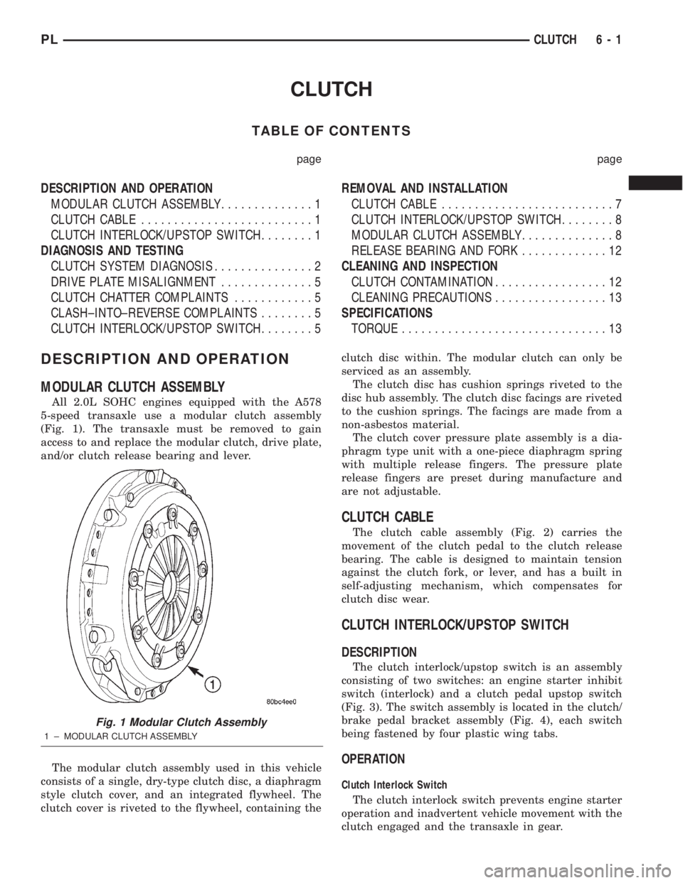
All 2.0L SOHC engines equipped with the A578
5-speed transaxle use a modular clutch assembly
(Fig. 1). The transaxle must be removed to gain
access to and replace the modular clutch, drive plate,
and/or clutch release bearing and lever.
The modular clutch assembly used in this vehicle
consists of a single, dry-type clutch disc, a diaphragm
style clutch cover, and an integrated flywheel. The
clutch cover is riveted to the flywheel, containing theclutch disc within. The modular clutch can only be
serviced as an assembly.
The clutch disc has cushion springs riveted to the
disc hub assembly. The clutch disc facings are riveted
to the cushion springs. The facings are made from a
non-asbestos material.
The clutch cover pressure plate assembly is a dia-
phragm type unit with a one-piece diaphragm spring
with multiple release fingers. The pressure plate
release fingers are preset during manufacture and
are not adjustable.
CLUTCH CABLE
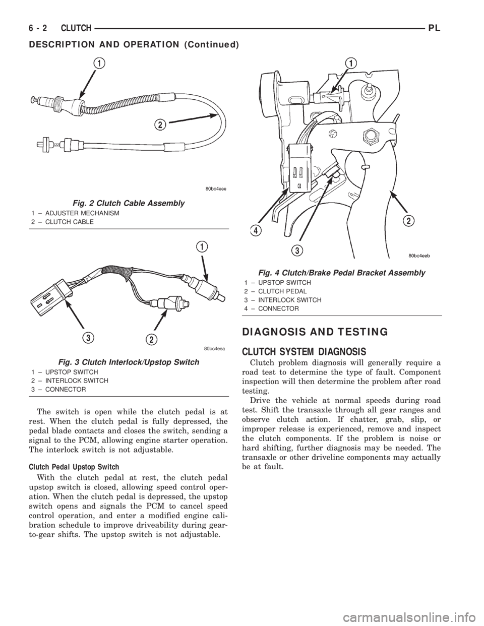
The clutch cable assembly (Fig. 2) carries the
movement of the clutch pedal to the clutch release
bearing. The cable is designed to maintain tension
against the clutch fork, or lever, and has a built in
self-adjusting mechanism, which compensates for
clutch disc wear.
CLUTCH INTERLOCK/UPSTOP SWITCH
DESCRIPTION
The clutch interlock/upstop switch is an assembly
consisting of two switches: an engine starter inhibit
switch (interlock) and a clutch pedal upstop switch
(Fig. 3). The switch assembly is located in the clutch/
brake pedal bracket assembly (Fig. 4), each switch
being fastened by four plastic wing tabs.
OPERATION
Clutch Interlock Switch
The clutch interlock switch prevents engine starter
operation and inadvertent vehicle movement with the
clutch engaged and the transaxle in gear.
Fig. 1 Modular Clutch Assembly
1 ± MODULAR CLUTCH ASSEMBLY
PLCLUTCH 6 - 1
Page 167 of 1285
The switch is open while the clutch pedal is at
rest. When the clutch pedal is fully depressed, the
pedal blade contacts and closes the switch, sending a
signal to the PCM, allowing engine starter operation.
The interlock switch is not adjustable.
Clutch Pedal Upstop Switch
With the clutch pedal at rest, the clutch pedal
upstop switch is closed, allowing speed control oper-
ation. When the clutch pedal is depressed, the upstop
switch opens and signals the PCM to cancel speed
control operation, and enter a modified engine cali-
bration schedule to improve driveability during gear-
to-gear shifts. The upstop switch is not adjustable.
DIAGNOSIS AND TESTING
CLUTCH SYSTEM DIAGNOSIS
Clutch problem diagnosis will generally require a
road test to determine the type of fault. Component
inspection will then determine the problem after road
testing.
Drive the vehicle at normal speeds during road
test. Shift the transaxle through all gear ranges and
observe clutch action. If chatter, grab, slip, or
improper release is experienced, remove and inspect
the clutch components. If the problem is noise or
hard shifting, further diagnosis may be needed. The
transaxle or other driveline components may actually
be at fault.
Fig. 2 Clutch Cable Assembly
1 ± ADJUSTER MECHANISM
2 ± CLUTCH CABLE
Fig. 3 Clutch Interlock/Upstop Switch
1 ± UPSTOP SWITCH
2 ± INTERLOCK SWITCH
3 ± CONNECTOR
Fig. 4 Clutch/Brake Pedal Bracket Assembly
1 ± UPSTOP SWITCH
2 ± CLUTCH PEDAL
3 ± INTERLOCK SWITCH
4 ± CONNECTOR
6 - 2 CLUTCHPL
DESCRIPTION AND OPERATION (Continued)