2000 DODGE NEON oil filter
[x] Cancel search: oil filterPage 3 of 1285
LUBRICANTS AND GREASES
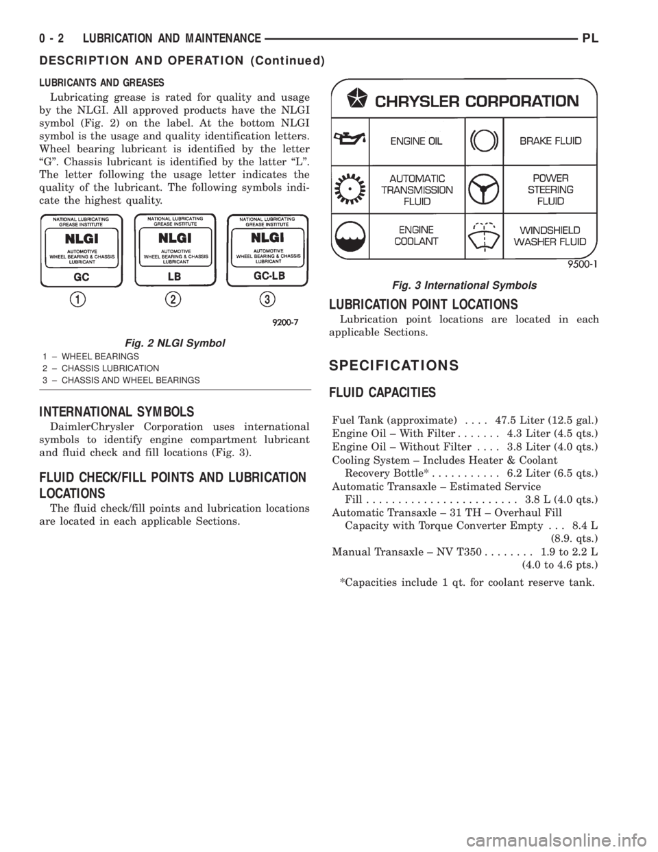
Lubricating grease is rated for quality and usage
by the NLGI. All approved products have the NLGI
symbol (Fig. 2) on the label. At the bottom NLGI
symbol is the usage and quality identification letters.
Wheel bearing lubricant is identified by the letter
ªGº. Chassis lubricant is identified by the latter ªLº.
The letter following the usage letter indicates the
quality of the lubricant. The following symbols indi-
cate the highest quality.
INTERNATIONAL SYMBOLS
DaimlerChrysler Corporation uses international
symbols to identify engine compartment lubricant
and fluid check and fill locations (Fig. 3).
FLUID CHECK/FILL POINTS AND LUBRICATION
LOCATIONS
The fluid check/fill points and lubrication locations
are located in each applicable Sections.
LUBRICATION POINT LOCATIONS
Lubrication point locations are located in each
applicable Sections.
SPECIFICATIONS
FLUID CAPACITIES
Fuel Tank (approximate)....47.5 Liter (12.5 gal.)
Engine Oil ± With Filter....... 4.3Liter (4.5 qts.)
Engine Oil ± Without Filter.... 3.8Liter (4.0 qts.)
Cooling System ± Includes Heater & Coolant
Recovery Bottle*........... 6.2Liter (6.5 qts.)
Automatic Transaxle ± Estimated Service
Fill........................ 3.8L(4.0 qts.)
Automatic Transaxle ± 31 TH ± Overhaul Fill
Capacity with Torque Converter Empty . . . 8.4 L
(8.9. qts.)
Manual Transaxle ± NV T350........ 1.9to2.2L
(4.0 to 4.6 pts.)
*Capacities include 1 qt. for coolant reserve tank.
Fig. 2 NLGI Symbol
1 ± WHEEL BEARINGS
2 ± CHASSIS LUBRICATION
3 ± CHASSIS AND WHEEL BEARINGS
Fig. 3 International Symbols
0 - 2 LUBRICATION AND MAINTENANCEPL
DESCRIPTION AND OPERATION (Continued)
Page 4 of 1285
MAINTENANCE SCHEDULES
TABLE OF CONTENTS
page page
DESCRIPTION AND OPERATION
MAINTENANCE SCHEDULES................3
SPECIFICATIONS
UNSCHEDULED INSPECTION................3SCHEDULE ± A...........................3
SCHEDULE ± B...........................4
DESCRIPTION AND OPERATION
MAINTENANCE SCHEDULES
There are two maintenance schedules that show
proper service for your vehicle.
First is Schedule ±A. It lists all the scheduled
maintenance to be performed under ªnormalº operat-
ing conditions.
Second is Schedule ±B. It is a schedule for vehi-
cles that are operated under the following conditions:
²Frequent short trip driving less than 5 miles (8
km)
²Frequent driving in dusty conditions
²Extensive idling
²More than 50% of the driving is at sustained
high speeds during hot weather, above 90É F (32É C)
SPECIFICATIONS
UNSCHEDULED INSPECTION
At Each Stop For Fuel
²Check engine oil level and add as required.
²Check windshield washer solvent and add as
required.
Once A Month
²Check tire pressure and look for unusual wear
or damage.
²Inspect the battery and clean and tighten termi-
nals as required.
²Check fluid levels of coolant reservoir, brake
master cylinder, power steering and transmission.
Add fluid as required.
²Check all lights and all other electrical items for
correct operation.
At Each Oil Change
²Inspect the exhaust system.
²Inspect brake hoses.
²Inspect the CV joints and front suspension com-
ponent boots and seals.²Rotate the tires at each oil change interval
shown on Schedule ± A (7,500 miles - 12 000 km) or
every other interval on Schedule ± B (6,000 miles -
10 000 km).
²Check the engine coolant level, hoses, and
clamps.
If mileage is less than 7,500 miles (12 000 km)
yearly, replace the engine oil filter at each oil change.
EMISSION CONTROL SYSTEM MAINTENANCE
The scheduled emission maintenance listed inbold
typeon the Maintenance Schedules, must be done at
the mileage specified to assure the continued proper
functioning of the emission control system. These,
and all other maintenance services included in this
manual, should be done to provide the best vehicle
performance and reliability. More frequent mainte-
nance may be needed for vehicles in severe operating
conditions such as dusty areas and very short trip
driving.
FLUID FILL POINTS AND LUBRICATION
LOCATIONS
The fluid fill/check locations and lubrication loca-
tions are located in each applicable group.
SCHEDULE ± A
7,500 Miles (12 000 km) or at 6 months
²Change the engine oil.
²Replace the engine oil filter.
15,000 Miles (24 000 km) or at 12 months
²Change the engine oil.
²Replace the engine oil filter.
²Adjust the drive belt tension.
22,500 Miles (36 000 km) or at 18 months
²Change the engine oil.
²Replace the engine oil filter.
²Inspect the front brake pads and rear brake lin-
ings.
PLLUBRICATION AND MAINTENANCE 0 - 3
Page 5 of 1285

30,000 Miles (48 000 km) or at 24 months
²Change the engine oil.
²Replace the engine oil filter.
²Lubricate the front suspension lower ball joint.
²Inspect the tie rod ends and boot seals.
²Adjust the drive belt tension.
²Replace the engine air cleaner element (fil-
ter).
²Replace the engine spark plugs
²Change the automatic transaxle fluid.
37,500 Miles (60 000 km) or at 30 months
²Change the engine oil.
²Replace the engine oil filter.
45,000 Miles (72 000 km) or at 36 months
²Change the engine oil.
²Replace the engine oil filter.
²Inspect the front brake pads and rear brake lin-
ings.
²Adjust the drive belt tension.
²Flush and replace the engine coolant at 36
months, regardless of mileage.
52,500 Miles (84 000 km) or at 42 months
²Change the engine oil.
²Replace the engine oil filter.
²Flush and replace the engine coolant if not done
at 36 months.
60,000 Miles (96 000 km) or at 48 months
²Change the engine oil.
²Replace the engine oil filter.
²Check the PCV valve and replace, if neces-
sary. Not required if previously changed.*
²Lubricate the front suspension lower ball joints.
²Replace the drive belts.
²Replace the engine air cleaner element (fil-
ter).
²Replace the ignition cables.
²Replace the spark plugs.
²Change the automatic transaxle fluid.
67,500 Miles (108 000 km) or at 54 months
²Change the engine oil.
²Replace the engine oil filter.
²Inspect the front brake pads and rear brake lin-
ings.
75,000 Miles (120 000 km) or at 60 months
²Change the engine oil.
²Replace the engine oil filter.
²Adjust the drive belt tension.
²Flush and replace engine coolant if has been
30,000 miles (48 000 km) or 24 months since last
change.
82,500 Miles (132 000 km) or at 66 months
²Change the engine oil.
²Replace the engine oil filter.
²Flush and replace engine coolant if it has been
30,000 miles (48 000 km) or 24 months since last
change.
90,000 Miles (144 000 km) or at 72 months
²Change the engine oil.
²Replace the engine oil filter.
²Check the PCV valve and replace, if neces-
sary. Not required if previously changed.*
²Lubricate the front suspension lower ball joints.
²Inspect the front brake pads and rear brake lin-
ings.
²Adjust the drive belt tension.
²Replace the engine air cleaner element (fil-
ter).
²Replace the spark plugs.
²Inspect the serpentine drive belt, replace if nec-
essary. This maintenance is not required if the belt
was previously replaced.
²Change the automatic transaxle fluid.
97,500 Miles (156 000 km) or at 78 months
²Change the engine oil.
²Replace the engine oil filter.
105,000 Miles (168 000 km) or at 84 months
²Change the engine oil.
²Replace the engine oil filter.
²Replace the engine timing belt.
²Adjust the drive belt tension.
*This maintenance is recommended by Daimler-
Chrysler Corporation to the owner but is not
required to maintain the emissions warranty.
NOTE: Inspection and service should also be per-
formed anytime a malfunction is observed or sus-
pected. Retain all receipts.
SCHEDULE ± B
3,000 Miles (5 000 km)
²Change the engine oil.
6,000 Miles (10 000 km)
²Change the engine oil.
²Replace the engine oil filter.
9,000 Miles (14 000 km)
²Change the engine oil.
²Inspect the front brake pads and rear brake lin-
ings.
0 - 4 LUBRICATION AND MAINTENANCEPL
SPECIFICATIONS (Continued)
Page 6 of 1285

12,000 Miles (19 000 km)
²Change the engine oil.
²Replace the engine oil filter.
15,000 Miles (24 000 km)
²Change the engine oil.
²Adjust the drive belt tension.
²Inspect theengine air cleaner element (fil-
ter).Replace as necessary.*
²Change the automatic transaxle fluid/filter and
adjust the bands.
18,000 Miles (29 000 km)
²Change the engine oil.
²Replace the engine oil filter.
²Inspect the front brake pads and rear brake lin-
ings.
21,000 Miles (34 000 km)
²Change the engine oil.
24,000 Miles (38 000 km)
²Change the engine oil.
²Replace the engine oil filter.
27,000 Miles (43 000 km)
²Change the engine oil.
²Inspect the front brake pads and rear brake lin-
ings.
30,000 Miles (48 000 km)
²Change the engine oil.
²Replace the engine oil filter.
²Inspect thePCV valveand replace as neces-
sary.*
²Lubricate the front suspension lower ball joints.
²Adjust the drive belt tension.
²Replace theengine air cleaner element (fil-
ter).
²Replace thespark plugs
²Change the automatic transaxle fluid/filter and
adjust bands.
33,000 Miles (53 000 km)
²Change the engine oil.
36,000 Miles (58 000 km)
²Change the engine oil.
²Replace the engine oil filter.
²Inspect the front brake pads and rear brake lin-
ings.
²Flush and replace the engine coolant.
39,000 Miles (62 000 km)
²Change the engine oil.
42,000 Miles (67 000 km)
²Change the engine oil.
²Replace the engine oil filter.
45,000 Miles (72 000 km)
²Change the engine oil.
²Inspect the front brake pads and rear brake lin-
ings.
²Inspect theengine air cleaner element (fil-
ter).Replace as necessary.*
²Adjust the drive belt tension.
²Change the automatic transaxle fluid/filter and
adjust bands.
48,000 Miles (77 000 km)
²Change the engine oil.
²Replace the engine oil filter.
51,000 Miles (82 000 km)
²Change the engine oil.
²Flush and replace the engine coolant.
54,000 Miles (86 000 km)
²Change the engine oil.
²Replace the engine oil filter.
²Inspect the front brake pads and rear brake lin-
ings.
57,000 Miles (91 000 km)
²Change the engine oil.
60,000 Miles (96 000 km)
²Change the engine oil.
²Replace the engine oil filter.
²Inspect thePCV valveand replace if neces-
sary.*
²Lubricate the front suspension lower ball joints.
²Replace the drive belts.
²Replace theengine air cleaner element (fil-
ter).
²Replace theignition cables
²Replace thespark plugs
²Check and replace, if necessary, theengine tim-
ing belton 3.0 liter engines.
²Change the automatic transaxle fluid/filter and
adjust bands.
63,000 Miles (101 000 km)
²Change the engine oil.
²Inspect the front brake pads and rear brake lin-
ings.
66,000 Miles (106 000 km)
²Change the engine oil.
²Replace the engine oil filter.
PLLUBRICATION AND MAINTENANCE 0 - 5
SPECIFICATIONS (Continued)
Page 7 of 1285

69,000 Miles (110 000 km)
²Change the engine oil.
72,000 Miles (115 000 km)
²Change the engine oil.
²Replace the engine oil filter.
²Inspect the front brake pads and rear brake lin-
ings.
75,000 Miles (120 000 km)
²Change the engine oil.
²Adjust the drive belt tension.
²Inspect theengine air cleaner element (fil-
ter)and replace as necessary.*
²Change the automatic transaxle fluid/filter and
adjust bands.
78,000 Miles (125 000 km)
²Change the engine oil.
²Replace the engine oil filter.
81,000 Miles (130 000 km)
²Change the engine oil.
²Flush and replace the engine coolant.
²Inspect the front brake pads and rear brake lin-
ings.
84,000 Miles (134 000 km)
²Change the engine oil.
²Replace the engine oil filter.
87,000 Miles (139 000 km)
²Change the engine oil.
90,000 Miles (144 000 km)
²Change the engine oil.
²Replace the engine oil filter.
²Inspect front brake pads and rear brake linings
²Check thePCV valveand replace if necessary.
Not required if previously changed.*
²Lubricate the front suspension lower ball joint.
²Replace theengine air cleaner element (fil-
ter).²Replace thespark plugs
²Change the automatic transaxle fluid/filter and
adjust the bands.
93,000 Miles (149 000 km)
²Change the engine oil.
96,000 Miles (154 000 km)
²Change the engine oil.
²Replace the engine oil filter.
99,000 Miles (158 000 km)
²Change the engine oil.
²Inspect the front brake pads and rear brake lin-
ings.
102,000 Miles (163 000 km)
²Change the engine oil.
²Replace the engine oil filter.
105,000 Miles (168 000 km)
²Replace theengine timing belt.
²Change the engine oil.
²Adjust the drive belt tension.
²Inspect theengine air cleaner element (fil-
ter)and replace as necessary.*
²Change the automatic transaxle fluid/filter and
adjust the bands.
²Flush and replace the engine coolant.
* This maintenance is recommended by Daimler-
Chrysler Corporation to the owner but is not
required to maintain the emissions warranty.
NOTE: Operating the vehicle more than 50% in
heavy traffic during hot weather, above 90É F (32É
C), using vehicle for police, taxi, limousine type
operation or trailer towing require the more fre-
quent transaxle service noted in Schedule ± B. Per-
form these services if vehicle usually operate under
these conditions.
Inspection and service should also be performed
anytime a malfunction is observed or suspected.
0 - 6 LUBRICATION AND MAINTENANCEPL
SPECIFICATIONS (Continued)
Page 161 of 1285
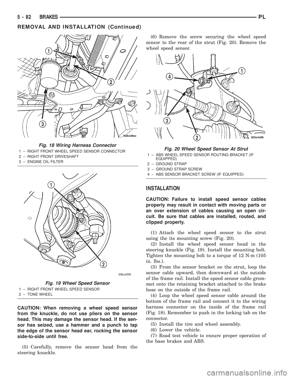
CAUTION: When removing a wheel speed sensor
from the knuckle, do not use pliers on the sensor
head. This may damage the sensor head. If the sen-
sor has seized, use a hammer and a punch to tap
the edge of the sensor head ear, rocking the sensor
side-to-side until free.
(5) Carefully, remove the sensor head from the
steering knuckle.(6) Remove the screw securing the wheel speed
sensor to the rear of the strut (Fig. 20). Remove the
wheel speed sensor.
INSTALLATION
CAUTION: Failure to install speed sensor cables
properly may result in contact with moving parts or
an over extension of cables causing an open cir-
cuit. Be sure that cables are installed, routed, and
clipped properly.
(1) Attach the wheel speed sensor to the strut
using the its mounting screw (Fig. 20).
(2) Install the wheel speed sensor head in the
steering knuckle (Fig. 19). Install the mounting bolt.
Tighten the mounting bolt to a torque of 12 N´m (105
in. lbs.).
(3) From the sensor bracket on the strut, loop the
sensor cable upward, then downward at the outside
of the frame rail. Install the speed sensor cable grom-
met onto the retaining bracket attached to the brake
hose on the outside of the frame rail.
(4) Loop the wheel speed sensor cable around the
bottom of the frame rail and connect it to the wiring
harness connector on the inside of the frame rail
(Fig. 18). Remember to push in the locking tab on the
connector.
(5) Install the tire and wheel assembly.
(6) Lower the vehicle.
(7) Road test vehicle to ensure proper operation of
the base brakes and ABS.
Fig. 18 Wiring Harness Connector
1 ± RIGHT FRONT WHEEL SPEED SENSOR CONNECTOR
2 ± RIGHT FRONT DRIVESHAFT
3 ± ENGINE OIL FILTER
Fig. 19 Wheel Speed Sensor
1 ± RIGHT FRONT WHEEL SPEED SENSOR
2 ± TONE WHEEL
Fig. 20 Wheel Speed Sensor At Strut
1 ± ABS WHEEL SPEED SENSOR ROUTING BRACKET (IF
EQUIPPED)
2 ± GROUND STRAP
3 ± GROUND STRAP SCREW
4 ± ABS SENSOR BRACKET SCREW (IF EQUIPPED)
5 - 82 BRAKESPL
REMOVAL AND INSTALLATION (Continued)
Page 238 of 1285
OPERATION
The Automatic Shutdown (ASD) relay supplies bat-
tery voltage to the fuel injectors, electronic ignition
coil and the heating elements in the oxygen sensors.
A buss bar in the Power Distribution Center (PDC)
supplies voltage to the solenoid side and contact side
of the relay. The fuse also protects the power circuit
for the fuel pump relay and pump. The fuse is
located in the PDC. Refer to the Wiring Diagrams for
circuit information.
The PCM controls the ASD relay by switching the
ground path for the solenoid side of the relay on and
off. The PCM turns the ground path off when the
ignition switch is in the Off position. When the igni-
tion switch is in On or Start, the PCM monitors the
crankshaft and camshaft position sensor signals to
determine engine speed and ignition timing (coil
dwell). If the PCM does not receive crankshaft and
camshaft position sensor signals when the ignition
switch is in the Run position, it will de-energize the
ASD relay.
CRANKSHAFT POSITION SENSORÐPCM
INPUT
DESCRIPTION
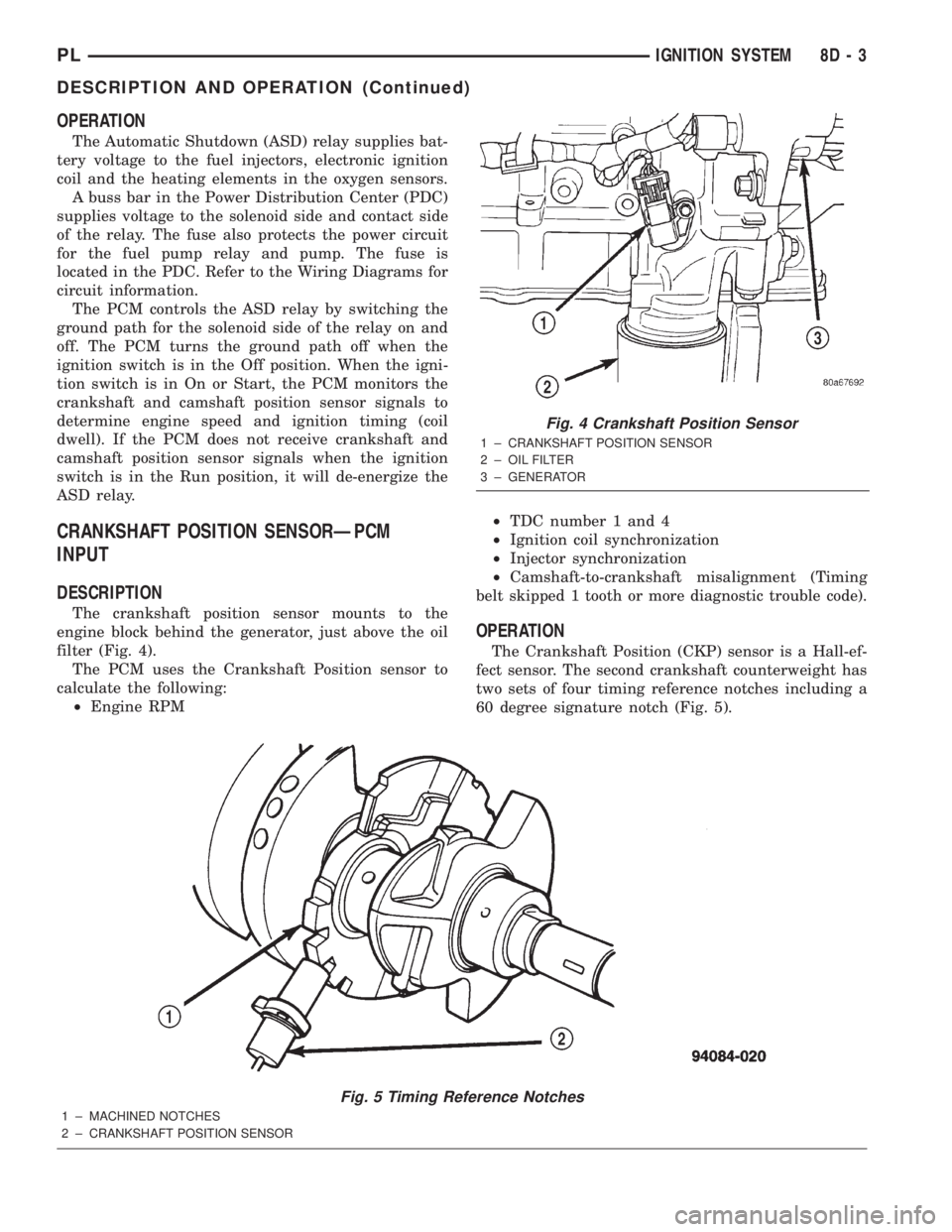
The crankshaft position sensor mounts to the
engine block behind the generator, just above the oil
filter (Fig. 4).
The PCM uses the Crankshaft Position sensor to
calculate the following:
²Engine RPM²TDC number 1 and 4
²Ignition coil synchronization
²Injector synchronization
²Camshaft-to-crankshaft misalignment (Timing
belt skipped 1 tooth or more diagnostic trouble code).
OPERATION
The Crankshaft Position (CKP) sensor is a Hall-ef-
fect sensor. The second crankshaft counterweight has
two sets of four timing reference notches including a
60 degree signature notch (Fig. 5).
Fig. 5 Timing Reference Notches
1 ± MACHINED NOTCHES
2 ± CRANKSHAFT POSITION SENSOR
Fig. 4 Crankshaft Position Sensor
1 ± CRANKSHAFT POSITION SENSOR
2 ± OIL FILTER
3 ± GENERATOR
PLIGNITION SYSTEM 8D - 3
DESCRIPTION AND OPERATION (Continued)
Page 243 of 1285
CRANKSHAFT POSITION SENSOR
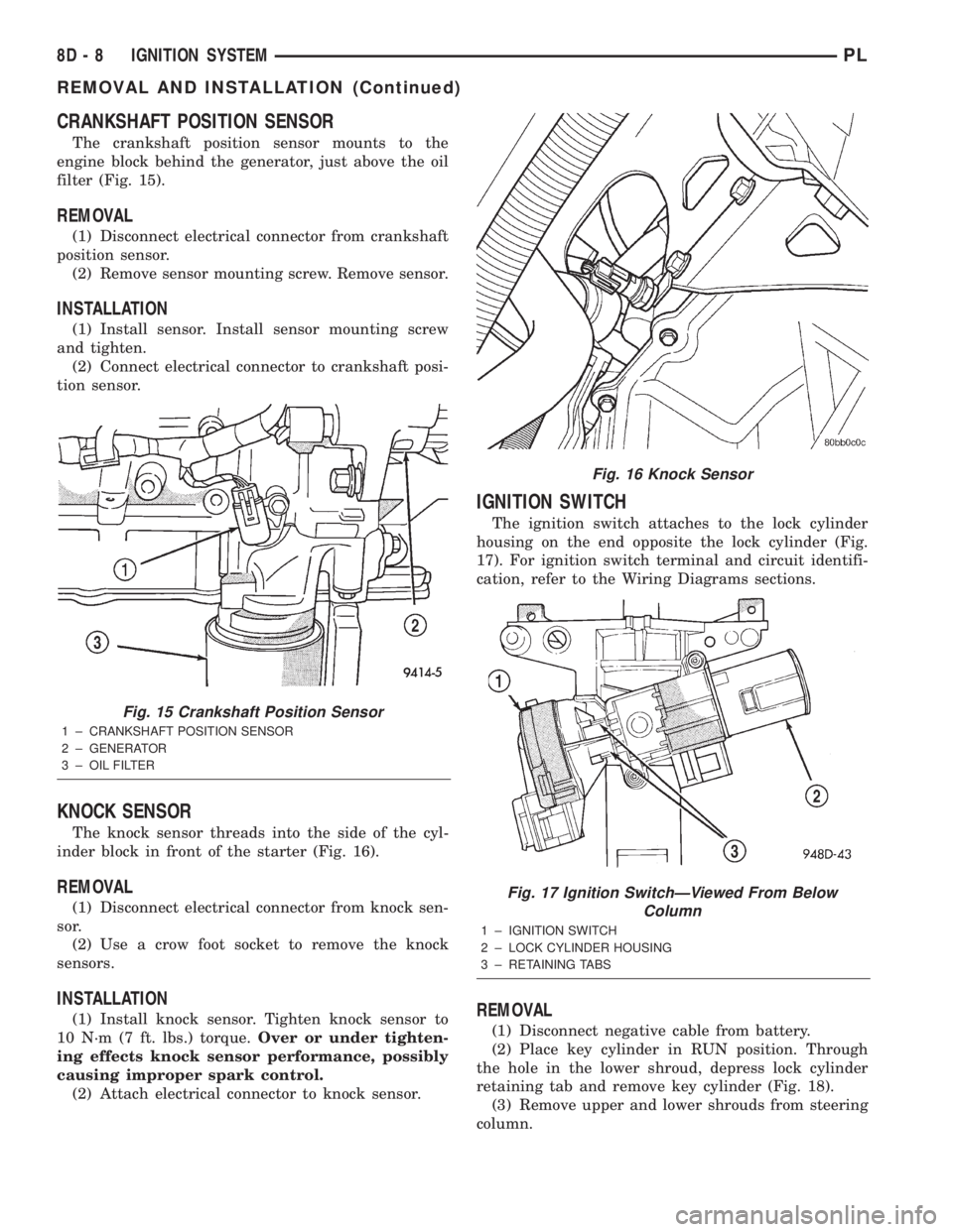
The crankshaft position sensor mounts to the
engine block behind the generator, just above the oil
filter (Fig. 15).
REMOVAL
(1) Disconnect electrical connector from crankshaft
position sensor.
(2) Remove sensor mounting screw. Remove sensor.
INSTALLATION
(1) Install sensor. Install sensor mounting screw
and tighten.
(2) Connect electrical connector to crankshaft posi-
tion sensor.
KNOCK SENSOR
The knock sensor threads into the side of the cyl-
inder block in front of the starter (Fig. 16).
REMOVAL
(1) Disconnect electrical connector from knock sen-
sor.
(2) Use a crow foot socket to remove the knock
sensors.
INSTALLATION
(1) Install knock sensor. Tighten knock sensor to
10 N´m (7 ft. lbs.) torque.Over or under tighten-
ing effects knock sensor performance, possibly
causing improper spark control.
(2) Attach electrical connector to knock sensor.
IGNITION SWITCH
The ignition switch attaches to the lock cylinder
housing on the end opposite the lock cylinder (Fig.
17). For ignition switch terminal and circuit identifi-
cation, refer to the Wiring Diagrams sections.
REMOVAL
(1) Disconnect negative cable from battery.
(2) Place key cylinder in RUN position. Through
the hole in the lower shroud, depress lock cylinder
retaining tab and remove key cylinder (Fig. 18).
(3) Remove upper and lower shrouds from steering
column.
Fig. 15 Crankshaft Position Sensor
1 ± CRANKSHAFT POSITION SENSOR
2 ± GENERATOR
3 ± OIL FILTER
Fig. 16 Knock Sensor
Fig. 17 Ignition SwitchÐViewed From Below
Column
1 ± IGNITION SWITCH
2 ± LOCK CYLINDER HOUSING
3 ± RETAINING TABS
8D - 8 IGNITION SYSTEMPL
REMOVAL AND INSTALLATION (Continued)