2000 DODGE NEON stop start
[x] Cancel search: stop startPage 228 of 1285
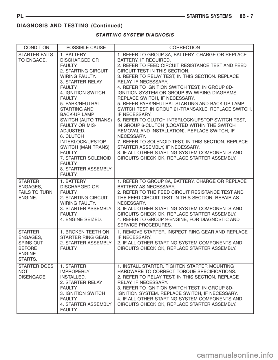
STARTING SYSTEM DIAGNOSIS
CONDITION POSSIBLE CAUSE CORRECTION
STARTER FAILS
TO ENGAGE.1. BATTERY
DISCHARGED OR
FAULTY.
2. STARTING CIRCUIT
WIRING FAULTY.
3. STARTER RELAY
FAULTY.
4. IGNITION SWITCH
FAULTY.
5. PARK/NEUTRAL
STARTING AND
BACK-UP LAMP
SWITCH (AUTO TRANS)
FAULTY OR MIS-
ADJUSTED.
6. CLUTCH
INTERLOCK/UPSTOP
SWITCH (MAN TRANS)
FAULTY.
7. STARTER SOLENOID
FAULTY.
8. STARTER ASSEMBLY
FAULTY.1. REFER TO GROUP 8A, BATTERY. CHARGE OR REPLACE
BATTERY, IF REQUIRED.
2. REFER TO FEED CIRCUIT RESISTANCE TEST AND FEED
CIRCUIT TEST IN THIS SECTION.
3. REFER TO RELAY TEST, IN THIS SECTION. REPLACE
RELAY, IF NECESSARY.
4. REFER TO IGNITION SWITCH TEST, IN GROUP 8D-
IGNITION SYSTEM OR GROUP 8W-WIRING DIAGRAMS.
REPLACE SWITCH, IF NECESSARY.
5. REFER PARK/NEUTRAL STARTING AND BACK-UP LAMP
SWITCH TEST IN GROUP 21-TRANSAXLE. REPLACE SWITCH,
IF NECESSARY.
6. REFER TO CLUTCH INTERLOCK/UPSTOP SWITCH TEST,
IN GROUP 6-CLUTCH (LOCATED WITHIN THE SWITCH
REMOVAL AND INSTALLATION). REPLACE SWITCH, IF
NECESSARY.
7. REFER TO SOLENOID TEST, IN THIS SECTION. REPLACE
STARTER ASSEMBLY, IF NECESSARY.
8. IF ALL OTHER STARTING SYSTEM COMPONENTS AND
CIRCUITS CHECK OK, REPLACE STARTER ASSEMBLY.
STARTER
ENGAGES,
FAILS TO TURN
ENGINE.1. BATTERY
DISCHARGED OR
FAULTY.
2. STARTING CIRCUIT
WIRING FAULTY.
3. STARTER ASSEMBLY
FAULTY.
4. ENGINE SEIZED.1. REFER TO GROUP 8A, BATTERY. CHARGE OR REPLACE
BATTERY AS NECESSARY.
2. REFER TO THE FEED CIRCUIT RESISTANCE TEST AND
THE FEED CIRCUIT TEST IN THIS SECTION. REPAIR AS
NECESSARY.
3. IF ALL OTHER STARTING SYSTEM COMPONENTS AND
CIRCUITS CHECK OK, REPLACE STARTER ASSEMBLY.
4. REFER TO GROUP 9-ENGINE, FOR DIAGNOSTIC AND
SERVICE PROCEDURES.
STARTER
ENGAGES,
SPINS OUT
BEFORE
ENGINE
STARTS.1. BROKEN TEETH ON
STARTER RING GEAR.
2. STARTER ASSEMBLY
FAULTY.1. REMOVE STARTER. INSPECT RING GEAR AND REPLACE
IF NECESSARY.
2. IF ALL OTHER STARTING SYSTEM COMPONENTS AND
CIRCUITS CHECK OK, REPLACE STARTER ASSEMBLY.
STARTER DOES
NOT
DISENGAGE.1. STARTER
IMPROPERLY
INSTALLED.
2. STARTER RELAY
FAULTY.
3. IGNITION SWITCH
FAULTY.
4. STARTER ASSEMBLY
FAULTY.1. INSTALL STARTER. TIGHTEN STARTER MOUNTING
HARDWARE TO CORRECT TORQUE SPECIFICATIONS.
2. REFER TO RELAY TEST, IN THIS SECTION. REPLACE
RELAY, IF NECESSARY.
3. REFER TO IGNITION SWITCH TEST, IN GROUP 8D-
IGNITION SYSTEM. REPLACE SWITCH, IF NECESSARY.
4. IF ALL OTHER STARTING SYSTEM COMPONENTS AND
CIRCUITS CHECK OK, REPLACE STARTER ASSEMBLY.
PLSTARTING SYSTEMS 8B - 7
DIAGNOSIS AND TESTING (Continued)
Page 229 of 1285
REMOVAL AND INSTALLATION
SAFETY SWITCHES
For Removal and Installation of:
²Clutch Interlock/Upstop Switch, refer to
Removal and Installation in Group 6-Clutch.
²Park/Neutral Starting and Back-Up Lamp
Switch, refer to Removal and Installation in Group
21-Transaxle.
STARTER MOTOR
REMOVAL
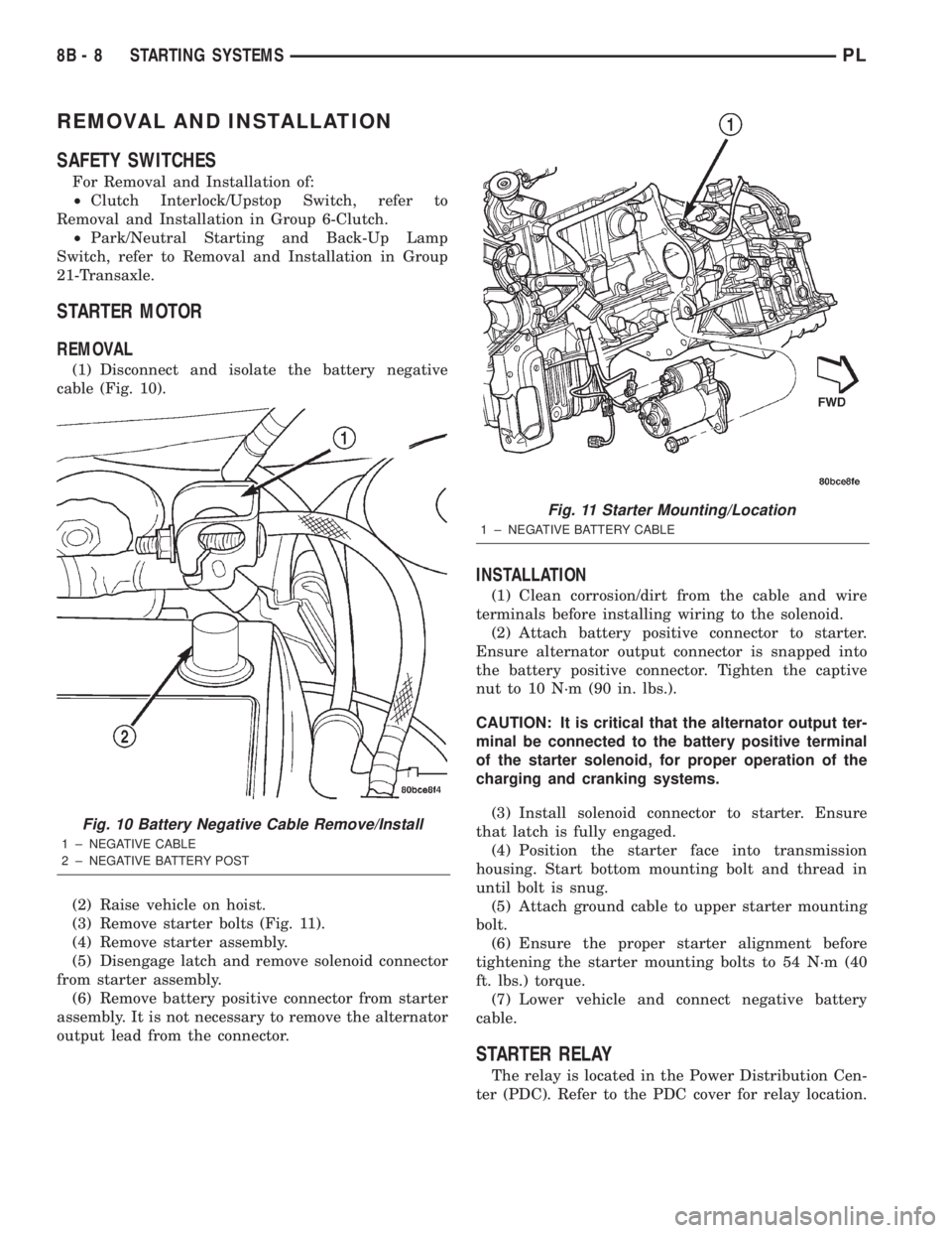
(1) Disconnect and isolate the battery negative
cable (Fig. 10).
(2) Raise vehicle on hoist.
(3) Remove starter bolts (Fig. 11).
(4) Remove starter assembly.
(5) Disengage latch and remove solenoid connector
from starter assembly.
(6) Remove battery positive connector from starter
assembly. It is not necessary to remove the alternator
output lead from the connector.
INSTALLATION
(1) Clean corrosion/dirt from the cable and wire
terminals before installing wiring to the solenoid.
(2) Attach battery positive connector to starter.
Ensure alternator output connector is snapped into
the battery positive connector. Tighten the captive
nut to 10 N´m (90 in. lbs.).
CAUTION: It is critical that the alternator output ter-
minal be connected to the battery positive terminal
of the starter solenoid, for proper operation of the
charging and cranking systems.
(3) Install solenoid connector to starter. Ensure
that latch is fully engaged.
(4) Position the starter face into transmission
housing. Start bottom mounting bolt and thread in
until bolt is snug.
(5) Attach ground cable to upper starter mounting
bolt.
(6) Ensure the proper starter alignment before
tightening the starter mounting bolts to 54 N´m (40
ft. lbs.) torque.
(7) Lower vehicle and connect negative battery
cable.
STARTER RELAY
The relay is located in the Power Distribution Cen-
ter (PDC). Refer to the PDC cover for relay location.
Fig. 10 Battery Negative Cable Remove/Install
1 ± NEGATIVE CABLE
2 ± NEGATIVE BATTERY POST
Fig. 11 Starter Mounting/Location
1 ± NEGATIVE BATTERY CABLE
8B - 8 STARTING SYSTEMSPL
Page 300 of 1285
(a) If no voltage, repair wiring as necessary. If
OK, go to Step b.
(b) Check wiper switch low speed. Connect volt-
meter positive lead to terminal 6 of the wiper
switch connector. Move wiper stalk to LOW posi-
tion. If no voltage, replace switch.
(c) Check wiper switch high speed, connect volt-
meter positive lead to terminal 5 of the wiper
switch connector. Move wiper stalk to HIGH posi-
tion. If no voltage, replace switch.
(7) Disconnect motor connector and replace fuse 1
in fuse block.
(a) If fuse does not blow, replace motor.
(b) If fuse blows, disconnect wiper switch and
replace fuse.
(c) If fuse does not blow, replace switch.
(d) If fuse blows, repair wiring as necessary.
MOTOR OPERATES SLOWLY AT ALL SPEEDS
(1) Remove wiper arms and cowl screen. Discon-
nect motor linkage from motor. Connect an ammeter
between battery positive terminal and terminal 4 of
the motor connector. Turn wiper motor on and check
ampere reading.
If motor runs and ammeter reading is more than 6
amps, go to Step 2. If less than 6 amps, go to Step 3.
When replacing drive link nut tighten to 11 to 12
N´m (98 to 106 in. lbs.) torque.
(2) Using an ohmmeter, check the high and low
circuits for a short to ground. Refer to Group 8W,
Wiring Diagrams.
(3) Check to see if wiper linkage or pivots are
binding or caught.
WIPERS RUN AT HIGH SPEED WITH SWITCH IN
LOW SPEED POSITION OR WIPERS RUN AT LOW
SPEED WITH SWITCH IN HIGH SPEED POSITION.
(1) Check for crossed wires in the motor pigtail
wire connector. Refer to Group 8W, Wiring Diagrams.
(2) Check for crossed wires in harness connector
from wiper switch to motor.
(3) If OK, replace wiper switch.
WIPERS WILL OPERATE CONTINUOUSLY WITH
THE SWITCH IN THE INTERMITTENT POSITION -
WHEN WIPER SWITCH IS TURNED OFF, WIPERS
STOP WHEREVER THEY ARE WITHOUT
RETURNING TO PARK POSITION.
(1) Check at motor ground strap for a good ground.
(2) Turn ignition switch OFF. Disconnect the wiper
switch harness connector. Using an ohmmeter with
the motor in the park position, check for continuity
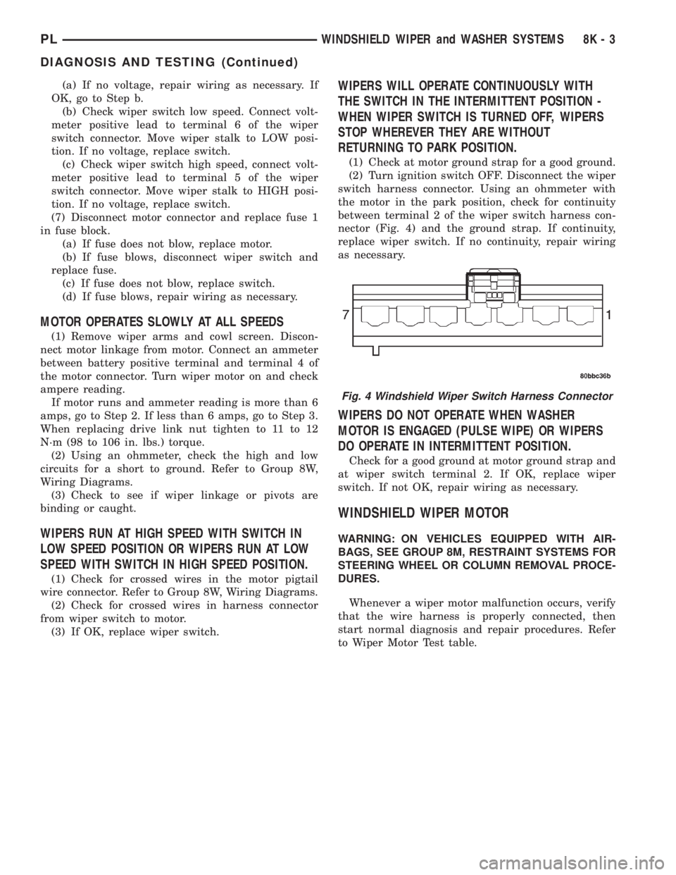
between terminal 2 of the wiper switch harness con-
nector (Fig. 4) and the ground strap. If continuity,
replace wiper switch. If no continuity, repair wiring
as necessary.
WIPERS DO NOT OPERATE WHEN WASHER
MOTOR IS ENGAGED (PULSE WIPE) OR WIPERS
DO OPERATE IN INTERMITTENT POSITION.
Check for a good ground at motor ground strap and
at wiper switch terminal 2. If OK, replace wiper
switch. If not OK, repair wiring as necessary.
WINDSHIELD WIPER MOTOR
WARNING: ON VEHICLES EQUIPPED WITH AIR-
BAGS, SEE GROUP 8M, RESTRAINT SYSTEMS FOR
STEERING WHEEL OR COLUMN REMOVAL PROCE-
DURES.
Whenever a wiper motor malfunction occurs, verify
that the wire harness is properly connected, then
start normal diagnosis and repair procedures. Refer
to Wiper Motor Test table.
Fig. 4 Windshield Wiper Switch Harness Connector
PLWINDSHIELD WIPER and WASHER SYSTEMS 8K - 3
DIAGNOSIS AND TESTING (Continued)
Page 377 of 1285
(3) After the ignition switch has been in the ON
position for about three seconds, but no more than
fifteen seconds, cycle the ignition switch back to the
OFF position. Replace the first valid Sentry Key in
the ignition lock cylinder with the second valid Sen-
try Key and turn the ignition switch back to the ON
position. Both operations must be performed within
15 seconds.
(4) About ten seconds after the completion of Step
3, the VTSS indicator LED will start to flash and a
single audible chime tone will sound to indicate that
the system has entered the ªCustomer Learnº pro-
gramming mode.
(5) Within about fifty seconds of entering the ªCus-
tomer Learnº programming mode, turn the ignition
switch to the OFF position, replace the valid Sentry
Key with a blank Sentry Key transponder, and turn
the ignition switch back to the ON position.
(6) About ten seconds after the completion of Step
5, a single audible chime tone will sound and the
VTSS indicator LED will stop flashing and stay on
solid for about three seconds to indicate that the
blank Sentry Key transponder has been successfully
programmed. The SKIS will immediately return to
normal system operation following exit from the
ªCustomer Learnº programming mode.
(7) Go back to Step 2 and repeat this process for
each additional Sentry Key transponder blank to be
programmed.
If any of the above steps is not completed in the
proper sequence, or within the allotted time, the
SKIS will automatically exit the ªCustomer Learnº
programming mode. The SKIS will also automatically
exit the ªCustomer Learnº programming mode if it
sees a non-blank Sentry Key transponder when it
should see a blank, if it has already programmed
eight valid Sentry Keys, or if the ignition switch is
turned to the OFF position for more than about fifty
seconds.
PROGRAMMING BLANK SENTRY KEY
TRANSPONDERS WITH A DRB lllTSCAN TOOL
When programming a blank Sentry Key transpon-
der, the key blank must first be cut to match the
ignition lock cylinder. It will also be necessary to
enter the vehicle's four digit PIN code into the DRB
IIItscan tool to enter the Sentry Key Immobilizer
Module's (SKIM's) secured access mode.
NOTE: Once a Sentry Key is programmed to a par-
ticular vehicle, it cannot be transferred to another
vehicle.
Insert the blank key into the ignition and turn it to
the RUN position. Using the DRB IIItscan tool,
select ªTheft Alarm,º then ªSKIM,º then ªMiscella-
neous.º Select ªProgram New Key.º Enter the fourdigit PIN code using the DRB IIIt. When program-
ming is completed, the SKIM will exit secured access
mode and display the status of the key. One of five
different status messages may be displayed as fol-
lows:
²ªProgramming Successfulº is displayed if SKIM
Sentry Key programming succeeds.
²ªLearned Key in Ignitionº is displayed if the key
in the ignition has already been programmed into
that vehicle's SKIM.
²ª8 Keys Already Learned (At The Maximum)
Programming Not Doneº is displayed if eight keys
have already been programmed into the SKIM. In
this case, if a new key needs to be added due to a
lost or defective key, the ªErase All Keysº function
(requires entering secured access mode) has to be
performed. Then the customer is seven keys plus the
new key MUST be reprogrammed into the SKIM.
²ªProgramming Not Attemptedº is displayed after
an ªErase All Keysº function is executed.
²ªProgramming Key Failedº is displayed if fur-
ther diagnosis is required.
²To learn additional keys, turn the ignition OFF,
remove the learned key, and insert the next new
blank key. Turn ignition to the RUN position and re-
enter the secured access mode function and repeat
the ªProgram New Keyº procedure outlined above.
SWITCHING OPERATING MODES/
CONFIGURING A NEW MODULE
To switch operating modes or to configure a new
module, a DRB IIItscan tool must be used.
(1) Hook up the DRB IIItscan tool to the Data
Link Connector (DLC) (Fig. 4).
(2) With the key in the ignition, turn the key to
the RUN position.
(3) After the DRB IIItscan tool initialization, per-
form the following:
(a) Select ªTheft Alarm.º
(b) Select ªVTSS.º
(c) Select ªMiscellaneous.º
(4) Once in the ªMiscellaneousº screen:
(a) If you wish to configure a new module, select
ªConfigure Module.º
(b) If you wish to put the module into customer
usage mode, select ªEnable VTSS.º
(c) If you wish to put the module into dealer lot
mode, select ªDealer Lot.º
8Q - 6 VEHICLE THEFT/SECURITY SYSTEMPL
SERVICE PROCEDURES (Continued)
Page 410 of 1285
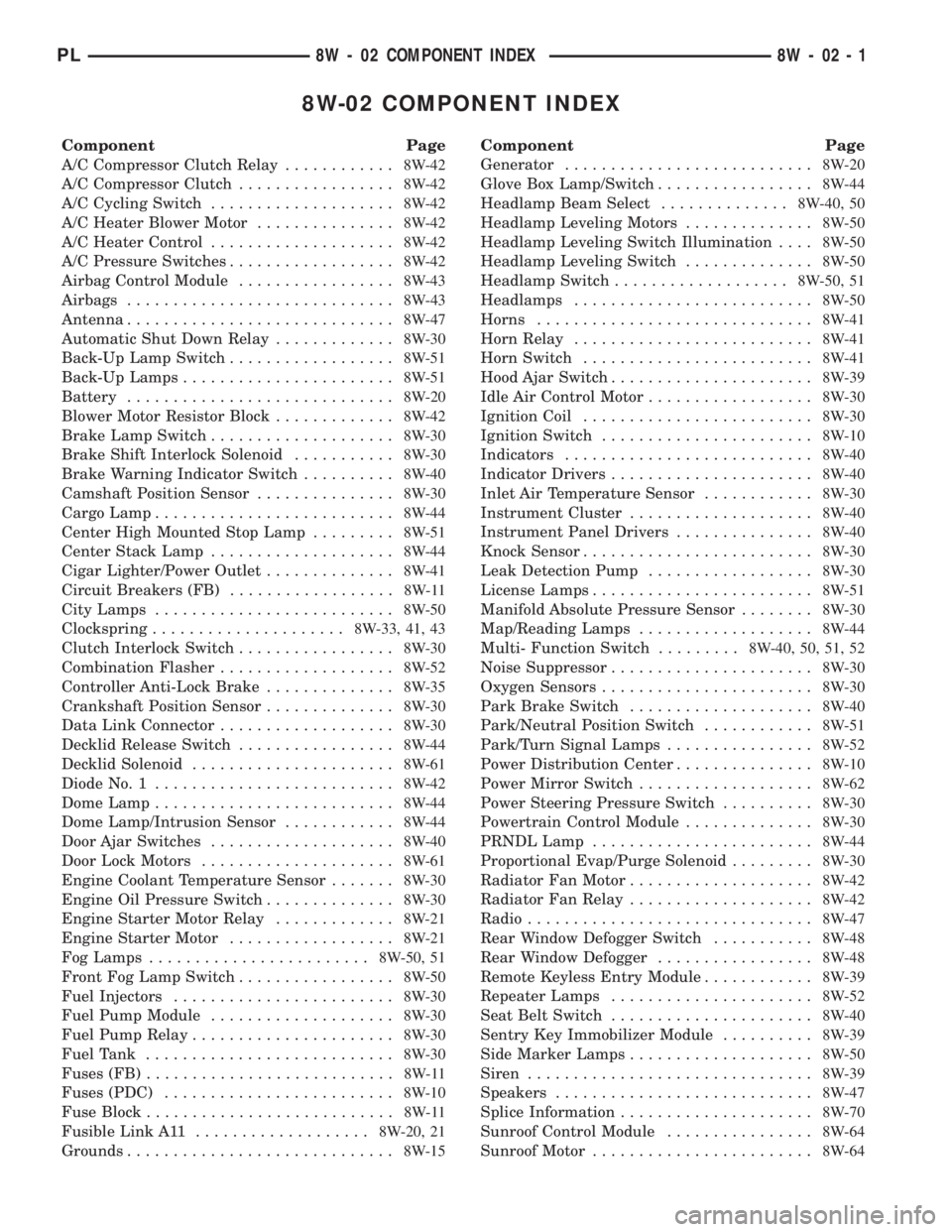
8W-02 COMPONENT INDEX
Component Page
A/C Compressor Clutch Relay............8W-42
A/C Compressor Clutch.................8W-42
A/C Cycling Switch....................8W-42
A/C Heater Blower Motor...............8W-42
A/C Heater Control....................8W-42
A/C Pressure Switches..................8W-42
Airbag Control Module.................8W-43
Airbags.............................8W-43
Antenna.............................8W-47
Automatic Shut Down Relay.............8W-30
Back-Up Lamp Switch..................8W-51
Back-Up Lamps.......................8W-51
Battery.............................8W-20
Blower Motor Resistor Block.............8W-42
Brake Lamp Switch....................8W-30
Brake Shift Interlock Solenoid...........8W-30
Brake Warning Indicator Switch..........8W-40
Camshaft Position Sensor...............8W-30
Cargo Lamp..........................8W-44
Center High Mounted Stop Lamp.........8W-51
Center Stack Lamp....................8W-44
Cigar Lighter/Power Outlet..............8W-41
Circuit Breakers (FB)..................8W-11
City Lamps..........................8W-50
Clockspring.....................8W-33, 41, 43
Clutch Interlock Switch.................8W-30
Combination Flasher...................8W-52
Controller Anti-Lock Brake..............8W-35
Crankshaft Position Sensor..............8W-30
Data Link Connector...................8W-30
Decklid Release Switch.................8W-44
Decklid Solenoid......................8W-61
Diode No. 1..........................8W-42
Dome Lamp..........................8W-44
Dome Lamp/Intrusion Sensor............8W-44
Door Ajar Switches....................8W-40
Door Lock Motors.....................8W-61
Engine Coolant Temperature Sensor.......8W-30
Engine Oil Pressure Switch..............8W-30
Engine Starter Motor Relay.............8W-21
Engine Starter Motor..................8W-21
Fog Lamps........................8W-50, 51
Front Fog Lamp Switch.................8W-50
Fuel Injectors........................8W-30
Fuel Pump Module....................8W-30
Fuel Pump Relay......................8W-30
Fuel Tank...........................8W-30
Fuses (FB)...........................8W-11
Fuses (PDC).........................8W-10
Fuse Block...........................8W-11
Fusible Link A11...................8W-20, 21
Grounds.............................8W-15Component Page
Generator...........................8W-20
Glove Box Lamp/Switch.................8W-44
Headlamp Beam Select..............8W-40, 50
Headlamp Leveling Motors..............8W-50
Headlamp Leveling Switch Illumination....8W-50
Headlamp Leveling Switch..............8W-50
Headlamp Switch...................8W-50, 51
Headlamps..........................8W-50
Horns..............................8W-41
Horn Relay..........................8W-41
Horn Switch.........................8W-41
Hood Ajar Switch......................8W-39
Idle Air Control Motor..................8W-30
Ignition Coil.........................8W-30
Ignition Switch.......................8W-10
Indicators...........................8W-40
Indicator Drivers......................8W-40
Inlet Air Temperature Sensor............8W-30
Instrument Cluster....................8W-40
Instrument Panel Drivers...............8W-40
Knock Sensor.........................8W-30
Leak Detection Pump..................8W-30
License Lamps........................8W-51
Manifold Absolute Pressure Sensor........8W-30
Map/Reading Lamps...................8W-44
Multi- Function Switch.........8W-40, 50, 51, 52
Noise Suppressor......................8W-30
Oxygen Sensors.......................8W-30
Park Brake Switch....................8W-40
Park/Neutral Position Switch............8W-51
Park/Turn Signal Lamps................8W-52
Power Distribution Center...............8W-10
Power Mirror Switch...................8W-62
Power Steering Pressure Switch..........8W-30
Powertrain Control Module..............8W-30
PRNDL Lamp........................8W-44
Proportional Evap/Purge Solenoid.........8W-30
Radiator Fan Motor....................8W-42
Radiator Fan Relay....................8W-42
Radio...............................8W-47
Rear Window Defogger Switch...........8W-48
Rear Window Defogger.................8W-48
Remote Keyless Entry Module............8W-39
Repeater Lamps......................8W-52
Seat Belt Switch......................8W-40
Sentry Key Immobilizer Module..........8W-39
Side Marker Lamps....................8W-50
Siren...............................8W-39
Speakers............................8W-47
Splice Information.....................8W-70
Sunroof Control Module................8W-64
Sunroof Motor........................8W-64
PL8W - 02 COMPONENT INDEX 8W - 02 - 1
Page 412 of 1285
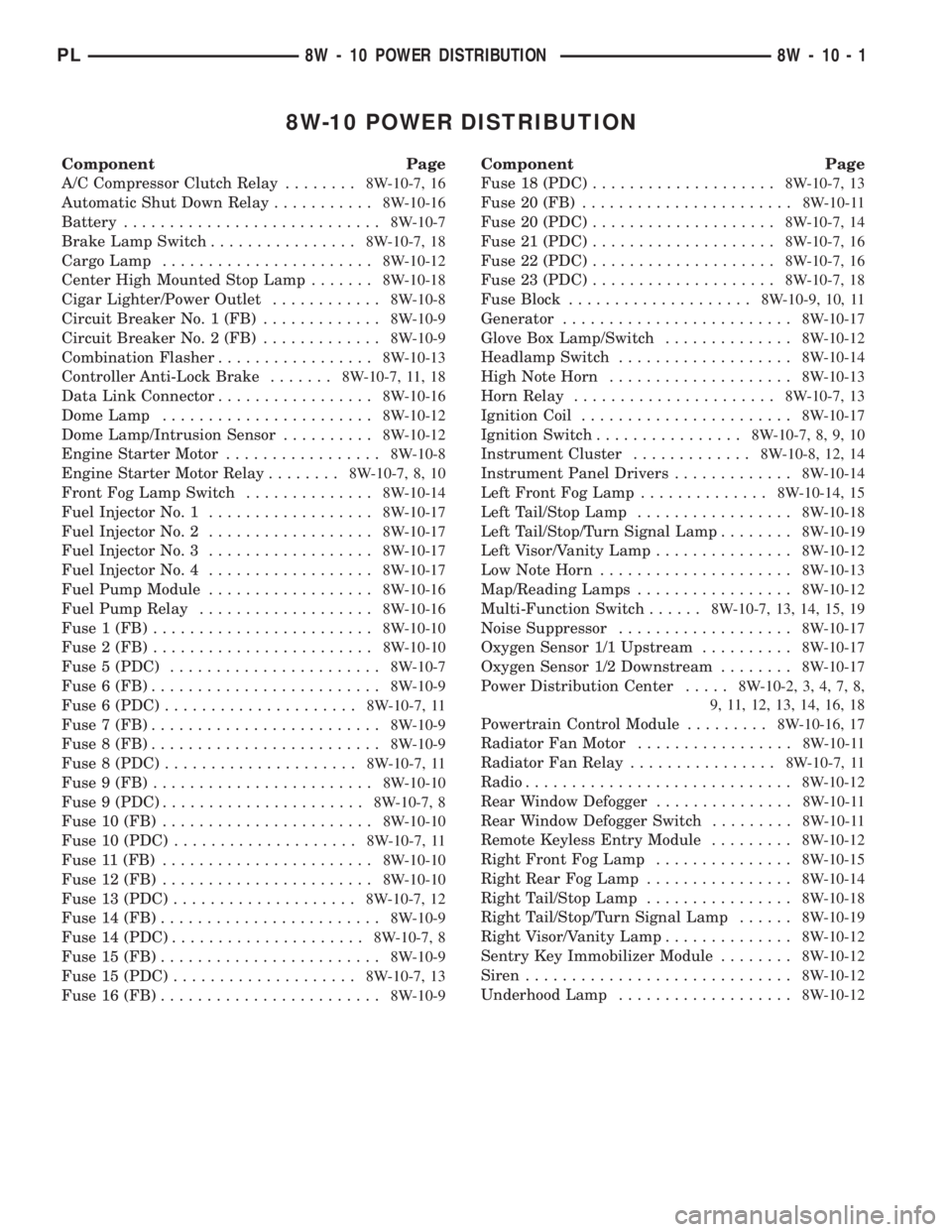
8W-10 POWER DISTRIBUTION
Component Page
A/C Compressor Clutch Relay........8W-10-7, 16
Automatic Shut Down Relay...........8W-10-16
Battery............................8W-10-7
Brake Lamp Switch................8W-10-7, 18
Cargo Lamp.......................8W-10-12
Center High Mounted Stop Lamp.......8W-10-18
Cigar Lighter/Power Outlet............8W-10-8
Circuit Breaker No. 1 (FB).............8W-10-9
Circuit Breaker No. 2 (FB).............8W-10-9
Combination Flasher.................8W-10-13
Controller Anti-Lock Brake.......8W-10-7, 11, 18
Data Link Connector.................8W-10-16
Dome Lamp.......................8W-10-12
Dome Lamp/Intrusion Sensor..........8W-10-12
Engine Starter Motor.................8W-10-8
Engine Starter Motor Relay........8W-10-7, 8, 10
Front Fog Lamp Switch..............8W-10-14
Fuel Injector No. 1..................8W-10-17
Fuel Injector No. 2..................8W-10-17
Fuel Injector No. 3..................8W-10-17
Fuel Injector No. 4..................8W-10-17
Fuel Pump Module..................8W-10-16
Fuel Pump Relay...................8W-10-16
Fuse 1 (FB)........................8W-10-10
Fuse 2 (FB)........................8W-10-10
Fuse 5 (PDC).......................8W-10-7
Fuse 6 (FB).........................8W-10-9
Fuse 6 (PDC).....................8W-10-7, 11
Fuse 7 (FB).........................8W-10-9
Fuse 8 (FB).........................8W-10-9
Fuse 8 (PDC).....................8W-10-7, 11
Fuse 9 (FB)........................8W-10-10
Fuse 9 (PDC)......................8W-10-7, 8
Fuse 10 (FB).......................8W-10-10
Fuse 10 (PDC)....................8W-10-7, 11
Fuse 11 (FB).......................8W-10-10
Fuse 12 (FB).......................8W-10-10
Fuse 13 (PDC)....................8W-10-7, 12
Fuse 14 (FB)........................8W-10-9
Fuse 14 (PDC).....................8W-10-7, 8
Fuse 15 (FB)........................8W-10-9
Fuse 15 (PDC)....................8W-10-7, 13
Fuse 16 (FB)........................8W-10-9Component Page
Fuse 18 (PDC)....................8W-10-7, 13
Fuse 20 (FB).......................8W-10-11
Fuse 20 (PDC)....................8W-10-7, 14
Fuse 21 (PDC)....................8W-10-7, 16
Fuse 22 (PDC)....................8W-10-7, 16
Fuse 23 (PDC)....................8W-10-7, 18
Fuse Block....................8W-10-9, 10, 11
Generator.........................8W-10-17
Glove Box Lamp/Switch..............8W-10-12
Headlamp Switch...................8W-10-14
High Note Horn....................8W-10-13
Horn Relay......................8W-10-7, 13
Ignition Coil.......................8W-10-17
Ignition Switch................8W-10-7, 8, 9, 10
Instrument Cluster.............8W-10-8, 12, 14
Instrument Panel Drivers.............8W-10-14
Left Front Fog Lamp..............8W-10-14, 15
Left Tail/Stop Lamp.................8W-10-18
Left Tail/Stop/Turn Signal Lamp........8W-10-19
Left Visor/Vanity Lamp...............8W-10-12
Low Note Horn.....................8W-10-13
Map/Reading Lamps.................8W-10-12
Multi-Function Switch......8W-10-7, 13, 14, 15, 19
Noise Suppressor...................8W-10-17
Oxygen Sensor 1/1 Upstream..........8W-10-17
Oxygen Sensor 1/2 Downstream........8W-10-17
Power Distribution Center.....8W-10-2, 3, 4, 7, 8,
9, 11, 12, 13, 14, 16, 18
Powertrain Control Module.........8W-10-16, 17
Radiator Fan Motor.................8W-10-11
Radiator Fan Relay................8W-10-7, 11
Radio.............................8W-10-12
Rear Window Defogger...............8W-10-11
Rear Window Defogger Switch.........8W-10-11
Remote Keyless Entry Module.........8W-10-12
Right Front Fog Lamp...............8W-10-15
Right Rear Fog Lamp................8W-10-14
Right Tail/Stop Lamp................8W-10-18
Right Tail/Stop/Turn Signal Lamp......8W-10-19
Right Visor/Vanity Lamp..............8W-10-12
Sentry Key Immobilizer Module........8W-10-12
Siren.............................8W-10-12
Underhood Lamp...................8W-10-12
PL8W - 10 POWER DISTRIBUTION 8W - 10 - 1
Page 474 of 1285
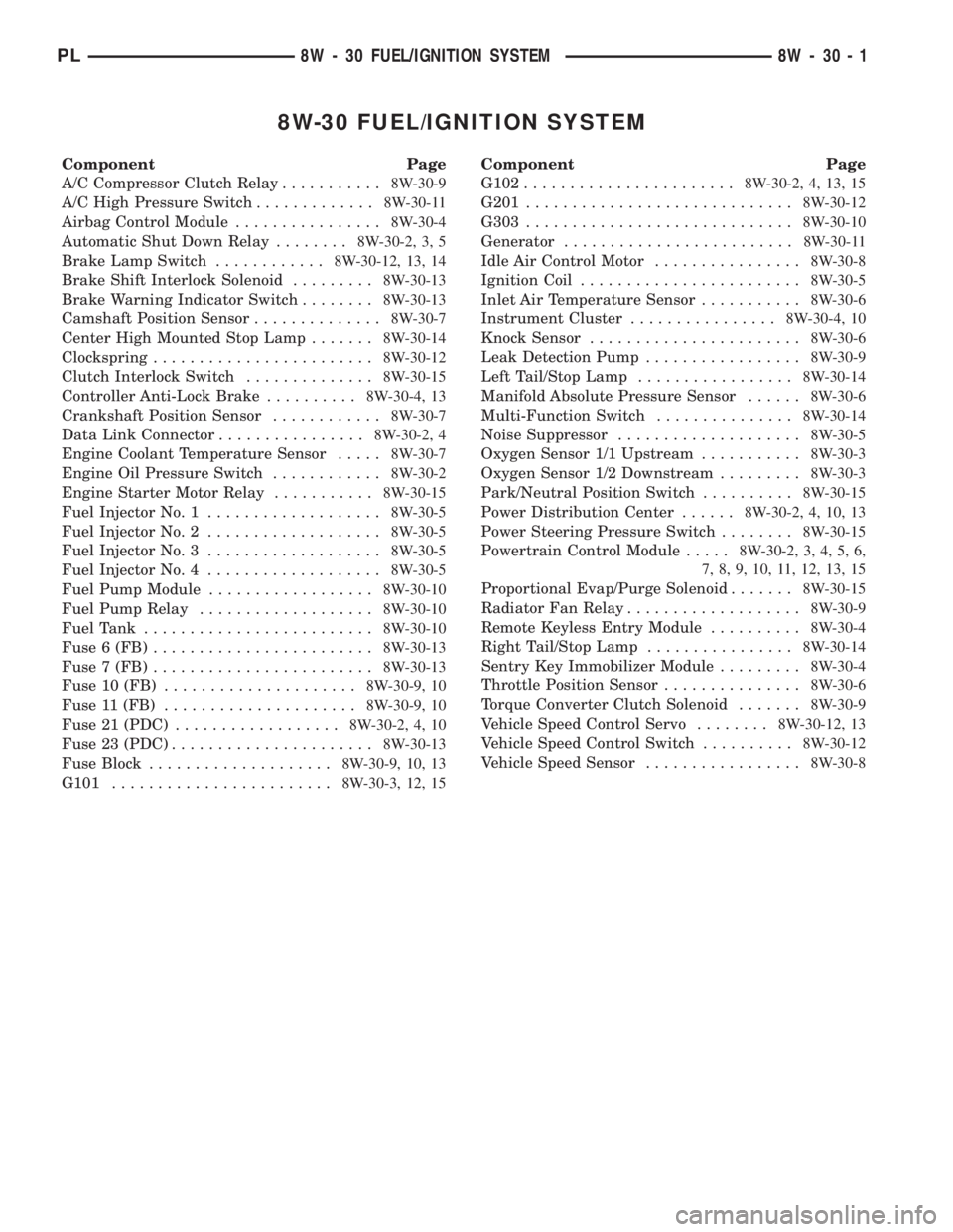
8W-30 FUEL/IGNITION SYSTEM
Component Page
A/C Compressor Clutch Relay...........8W-30-9
A/C High Pressure Switch.............8W-30-11
Airbag Control Module................8W-30-4
Automatic Shut Down Relay........8W-30-2, 3, 5
Brake Lamp Switch............8W-30-12, 13, 14
Brake Shift Interlock Solenoid.........8W-30-13
Brake Warning Indicator Switch........8W-30-13
Camshaft Position Sensor..............8W-30-7
Center High Mounted Stop Lamp.......8W-30-14
Clockspring........................8W-30-12
Clutch Interlock Switch..............8W-30-15
Controller Anti-Lock Brake..........8W-30-4, 13
Crankshaft Position Sensor............8W-30-7
Data Link Connector................8W-30-2, 4
Engine Coolant Temperature Sensor.....8W-30-7
Engine Oil Pressure Switch............8W-30-2
Engine Starter Motor Relay...........8W-30-15
Fuel Injector No. 1...................8W-30-5
Fuel Injector No. 2...................8W-30-5
Fuel Injector No. 3...................8W-30-5
Fuel Injector No. 4...................8W-30-5
Fuel Pump Module..................8W-30-10
Fuel Pump Relay...................8W-30-10
Fuel Tank.........................8W-30-10
Fuse 6 (FB)........................8W-30-13
Fuse 7 (FB)........................8W-30-13
Fuse 10 (FB).....................8W-30-9, 10
Fuse 11 (FB).....................8W-30-9, 10
Fuse 21 (PDC)..................8W-30-2, 4, 10
Fuse 23 (PDC)......................8W-30-13
Fuse Block....................8W-30-9, 10, 13
G101........................8W-30-3, 12, 15Component Page
G102.......................8W-30-2, 4, 13, 15
G201.............................8W-30-12
G303.............................8W-30-10
Generator.........................8W-30-11
Idle Air Control Motor................8W-30-8
Ignition Coil........................8W-30-5
Inlet Air Temperature Sensor...........8W-30-6
Instrument Cluster................8W-30-4, 10
Knock Sensor.......................8W-30-6
Leak Detection Pump.................8W-30-9
Left Tail/Stop Lamp.................8W-30-14
Manifold Absolute Pressure Sensor......8W-30-6
Multi-Function Switch...............8W-30-14
Noise Suppressor....................8W-30-5
Oxygen Sensor 1/1 Upstream...........8W-30-3
Oxygen Sensor 1/2 Downstream.........8W-30-3
Park/Neutral Position Switch..........8W-30-15
Power Distribution Center......8W-30-2, 4, 10, 13
Power Steering Pressure Switch........8W-30-15
Powertrain Control Module.....8W-30-2, 3, 4, 5, 6,
7, 8, 9, 10, 11, 12, 13, 15
Proportional Evap/Purge Solenoid.......8W-30-15
Radiator Fan Relay...................8W-30-9
Remote Keyless Entry Module..........8W-30-4
Right Tail/Stop Lamp................8W-30-14
Sentry Key Immobilizer Module.........8W-30-4
Throttle Position Sensor...............8W-30-6
Torque Converter Clutch Solenoid.......8W-30-9
Vehicle Speed Control Servo........8W-30-12, 13
Vehicle Speed Control Switch..........8W-30-12
Vehicle Speed Sensor.................8W-30-8
PL8W - 30 FUEL/IGNITION SYSTEM 8W - 30 - 1
Page 679 of 1285
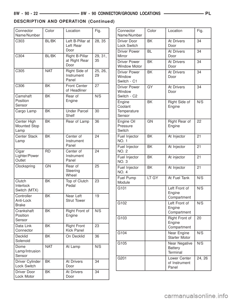
Connector
Name/NumberColor Location Fig.
C303 BL/BK Left B-Pillar at
Left Rear
Door28, 35
C304 BL/BK Right B-Pillar
at Right Rear
Door29, 31,
35
C305 NAT Right Side of
Instrument
Panel25, 26,
29
C306 BK Front Center
of Headliner27
Camshaft
Position
SensorBK Rear of
EngineN/S
Cargo Lamp BK Under Parcel
Shelf30
Center High
Mounted Stop
LampBK Rear of Lamp 36
Center Stack
LampBK Center of
Instrument
Panel24
Cigar
Lighter/Power
OutletRD Center of
Instrument
Panel24
Clockspring GN Rear of
Steering
Wheel25
Clutch
Interlock
Switch (MTX)BK Top of Clutch
Pedal23
Controller
Anti-Lock
BrakeBK Near Left
Strut Tower19
Crankshaft
Position
SensorBK Right Front of
EngineN/S
Data Link
ConnectorBK Right Front
Kick Panel23
Decklid
SolenoidBK On Decklid 36
Dome
Lamp/Intrusion
SensorNAT At Lamp N/S
Driver Cylinder
Lock SwitchBK At Drivers
Door34
Driver Door
Lock MotorBK At Drivers
Door34Connector
Name/NumberColor Location Fig.
Driver Door
Lock SwitchBK At Drivers
Door34
Driver Power
MirrorBL At Drivers
Door34
Driver Power
Window MotorBK At Drivers
Door34
Driver Power
Window
Switch - C1BK At Drivers
Door34
Driver Power
Window
Switch - C2GY At Drivers
Door34
Engine
Coolant
Temperature
SensorBK Right Side of
EngineN/S
Engine Oil
Pressure
SwitchGN Right Rear of
Engine22
Fuel Injector
NO. 1BK At Injector 21
Fuel Injector
NO. 2BK At Injector 21
Fuel Injector
NO. 3BK At injector 21
Fuel Injector
NO. 4BK At Injector 21
Fuel Pump
ModuleLT GY At Fuel Tank N/S
G101 Left Front of
Engine
CompartmentN/S
G102 Left Front of
Engine
CompartmentN/S
G103 Right Front of
Engine
Compartment20
G104 Near Engine
Starter MotorN/S
G105 Near Negative
Battery
TerminalN/S
G201 Lower Center
of Instrument
Panel24, 26
8W - 90 - 22 8W - 90 CONNECTOR/GROUND LOCATIONSPL
DESCRIPTION AND OPERATION (Continued)