2000 DODGE NEON jump start terminals
[x] Cancel search: jump start terminalsPage 223 of 1285

DIAGNOSIS AND TESTING
CONTROL CIRCUIT
The starter control circuit has:
²Starter solenoid
²Starter relay
²Park/Neutral Starting and Back-Up Lamp
Switch with automatic transmissions
²Clutch Interlock/Upstop Switch with manual
transmissions
²Ignition switch
²Battery
²All related wiring and connections
²Double Start Override algorithm located in the
PCM
CAUTION: Before performing any starter tests, the
ignition and fuel systems must be disabled.
²To disable ignition and fuel systems, disconnect
the Automatic Shutdown Relay (ASD). The ASD relay
is located in the in the Power Distribution Center
(PDC). Refer to the PDC cover for the proper relay
location.
STARTER SOLENOID
WARNING: CHECK TO ENSURE THAT THE TRANS-
MISSION IS IN THE PARK POSITION WITH THE
PARKING BRAKE APPLIED
(1) Verify battery condition. Battery must be in
good condition with a full charge before performing
any starter tests. Refer to Battery Tests.
(2) Perform Starter Solenoid test BEFORE per-
forming the starter relay test.
(3) Raise the vehicle.
(4) Perform a visual inspection of the starter/
starter solenoid for corrosion, loose connections or
faulty wiring.
(5) Lower the vehicle.
(6) Locate and remove the starter relay from the
Power Distribution Center (PDC). Refer to the PDC
label for relay identification and location.
(7) Connect a starter switch or a jumper wire
between the remote battery positive post and termi-
nal 87 of the starter relay connector.
(a) If engine cranks, starter motor and starter
solenoid is good. Go to the Starter Relay Test.(b) If engine does not crank or solenoid chatters,
check wiring and connectors from starter relay to
starter solenoid for loose or corroded connections.
Check for corroded connections at starter termi-
nals.
(c) Repeat test. If engine still fails to crank prop-
erly, trouble is within starter or starter mounted
solenoid, and replace starter.
STARTER RELAY
WARNING: CHECK TO ENSURE THAT THE TRANS-
MISSION IS IN THE PARK POSITION WITH THE
PARKING BRAKE APPLIED.
RELAY TEST
The starter relay is located in the Power Distribu-
tion Center (PDC) in the engine compartment. Refer
to the PDC label for relay identification and location.
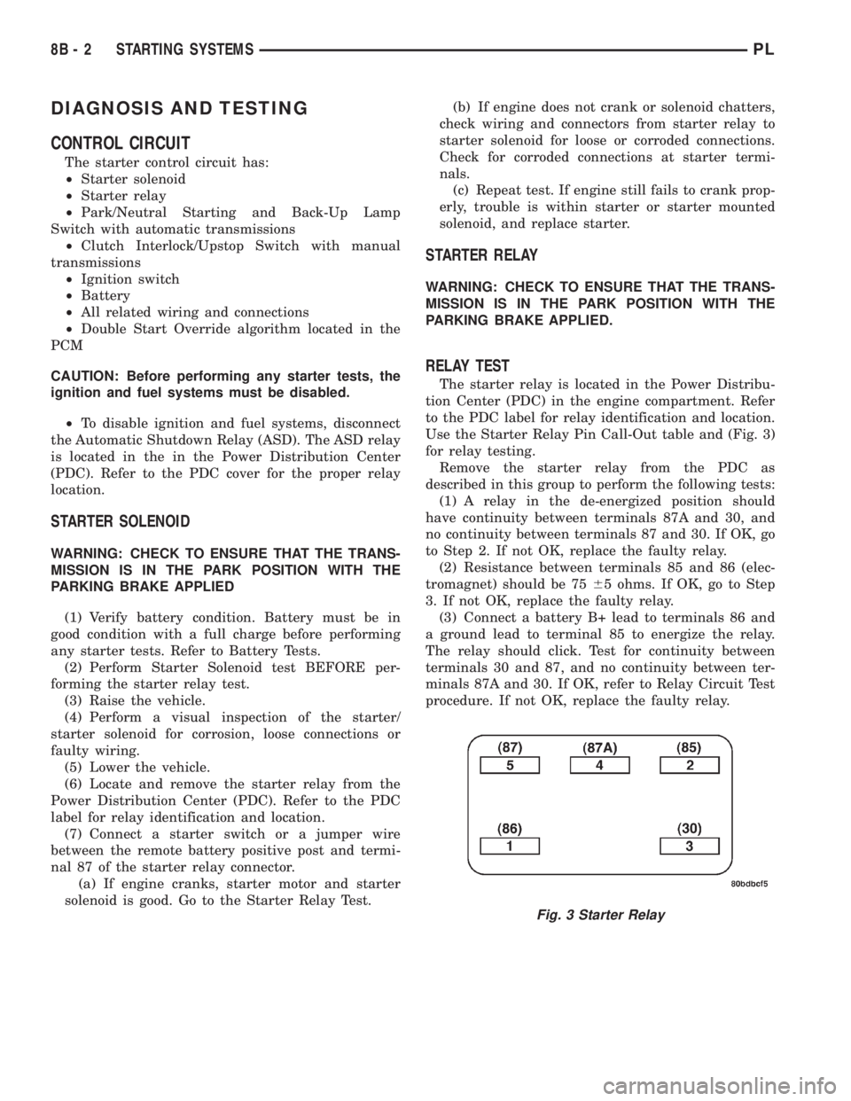
Use the Starter Relay Pin Call-Out table and (Fig. 3)
for relay testing.
Remove the starter relay from the PDC as
described in this group to perform the following tests:
(1) A relay in the de-energized position should
have continuity between terminals 87A and 30, and
no continuity between terminals 87 and 30. If OK, go
to Step 2. If not OK, replace the faulty relay.
(2) Resistance between terminals 85 and 86 (elec-
tromagnet) should be 7565 ohms. If OK, go to Step
3. If not OK, replace the faulty relay.
(3) Connect a battery B+ lead to terminals 86 and
a ground lead to terminal 85 to energize the relay.
The relay should click. Test for continuity between
terminals 30 and 87, and no continuity between ter-
minals 87A and 30. If OK, refer to Relay Circuit Test
procedure. If not OK, replace the faulty relay.
Fig. 3 Starter Relay
8B - 2 STARTING SYSTEMSPL
Page 1245 of 1285

POSSIBLE LOCATIONS OR CAUSE OF
OBSTRUCTED COOLANT FLOW
(1) Pinched or kinked heater hoses.
(2) Improper heater hose routing.
(3) Plugged heater hoses or supply and return
ports at cooling system connections, refer to Group 7,
Cooling System.
(4) Plugged heater core.
(5) Air locked heater core.
(6) If coolant flow is verified and outlet tempera-
ture is insufficient, a mechanical problem may exist.
POSSIBLE LOCATION OR CAUSE OF INSUFFICIENT
HEAT
(1) Obstructed cowl air intake.
(2) Obstructed heater system outlets.
(3) Blend-air door not functioning properly.
TEMPERATURE CONTROL
If temperature cannot be adjusted with the TEMP
lever on the control panel, the following could require
service:
(1) Blend-air door binding.
(2) Faulty blend-air door cable.
(3) Improper engine coolant temperature.
(4) Faulty Instrument Panel Control.
LOW PRESSURE CUT OFF SWITCH
The work area must not be below 21ÉC (70ÉF) to
test the compressor clutch circuit.
(1) With gear selector in park or neutral and park
brake set, start engine and allow to idle.
(2) Raise hood and disconnect low pressure cut off
switch connector boot.
(3) Using a suitable jumper wire, jump across the
terminals inside wire connector boot.
(4) If the compressor clutch does not engage, the
cycling clutch switch, wiring, relay, or fuse can be
defective. Refer to Group 8W, Wiring Diagrams.
(5) If clutch engages, connect manifold gauge set.
Read low pressure gauge. At pressure above 97 kPa
(14 psi) and above, low pressure out off switch will
complete the clutch circuit. If the low pressure gauge
reads below 140 kPa (20 psi), the system is low on
refrigerant charge or empty due to a leak. Refer to
Service Procedures, System Leak Checking in this
section.
(6) Install connector boot on switch and repeat
Step 3. If the clutch does not engage, replace the low
pressure cut off switch.
SYSTEM CHARGE LEVEL TEST
The procedure below should be used to check
and/or fill the refrigerant charge in the air condition-
ing system.
WARNING: AVOID BREATHING A/C REFRIGERANT
AND LUBRICANT VAPOR OR MIST. EXPOSURE MAY
IRRITATE EYES, NOSE AND THROAT. USE ONLY
APPROVED SERVICE EQUIPMENT MEETING SAE
REQUIREMENTS TO DISCHARGE R-134a SYSTEM.
IF ACCIDENTAL SYSTEM DISCHARGE OCCURS,
VENTILATE WORK AREA BEFORE RESUMING SER-
VICE.
R-134a SERVICE EQUIPMENT OR VEHICLE A/C
SYSTEM SHOULD NOT BE PRESSURE TESTED OR
LEAK TESTED WITH COMPRESSED AIR. MIXTURE
OF AIR and R-134a CAN BE COMBUSTIBLE AT ELE-
VATED PRESSURES. THESE MIXTURES ARE
POTENTIALLY DANGEROUS AND MAY RESULT IN
FIRE OR EXPLOSION CAUSING INJURY OR PROP-
ERTY DAMAGE.
NOTE: The maximum amount of R-134a refrigerant
that the air conditioning system holds is 765 grams
(27 oz. or 1.69 lbs.)
It is recommended to use the gauges or reclaim/re-
cycle equipment.
(1) Use a manifold gauge and check the liquid line
pressure.
(2) Attach a clamp-on thermocouple (P. S. E.
66-324-0014 or 80PK-1A) or equivalent to the liquid
line near the filter/drier.
(3) The vehicle must be in the following modes:
²Automatic transaxle in park or manual tran-
saxle in neutral.
²Engine at idle
²A/C controls set to outside air
²Panel mode
²A/C ON full cool
²Blower motor ON high speed
²Vehicle windows closed
(4) Operate system for a couple of minutes to allow
the system to stabilize.
(5) Observe filter/drier pressure and Liquid line
temperature. Using the Charge Determination Chart
(Fig. 14) determine where the system is currently
operating. If the system is not in the proper range,
reclaim all the refrigerant and recharge per A/C
label.
24 - 14 HEATING AND AIR CONDITIONINGPL
DIAGNOSIS AND TESTING (Continued)