2000 DODGE NEON index
[x] Cancel search: indexPage 92 of 1285
Some discoloration or wear of the rotor surface is
normal and does not require resurfacing when lin-
ings are replaced. If cracks or burned spots are evi-
dent, the rotor must be replaced.
ROTOR MINIMUM THICKNESS
Measure rotor thickness at the center of the brake
shoe contact surface. Replace the rotor if it is worn
below minimum thickness or if machining the rotor
will cause its thickness to fall below specifications.
CAUTION: Do not machine the rotor if it will cause
the rotor to fall below minimum thickness.
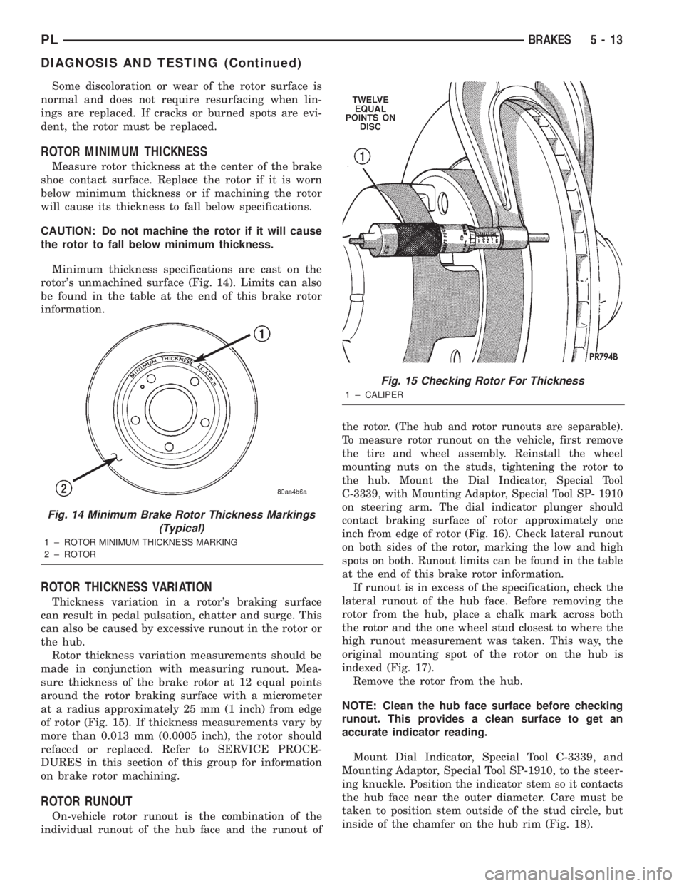
Minimum thickness specifications are cast on the
rotor's unmachined surface (Fig. 14). Limits can also
be found in the table at the end of this brake rotor
information.
ROTOR THICKNESS VARIATION
Thickness variation in a rotor's braking surface
can result in pedal pulsation, chatter and surge. This
can also be caused by excessive runout in the rotor or
the hub.
Rotor thickness variation measurements should be
made in conjunction with measuring runout. Mea-
sure thickness of the brake rotor at 12 equal points
around the rotor braking surface with a micrometer
at a radius approximately 25 mm (1 inch) from edge
of rotor (Fig. 15). If thickness measurements vary by
more than 0.013 mm (0.0005 inch), the rotor should
refaced or replaced. Refer to SERVICE PROCE-
DURES in this section of this group for information
on brake rotor machining.
ROTOR RUNOUT
On-vehicle rotor runout is the combination of the
individual runout of the hub face and the runout ofthe rotor. (The hub and rotor runouts are separable).
To measure rotor runout on the vehicle, first remove
the tire and wheel assembly. Reinstall the wheel
mounting nuts on the studs, tightening the rotor to
the hub. Mount the Dial Indicator, Special Tool
C-3339, with Mounting Adaptor, Special Tool SP- 1910
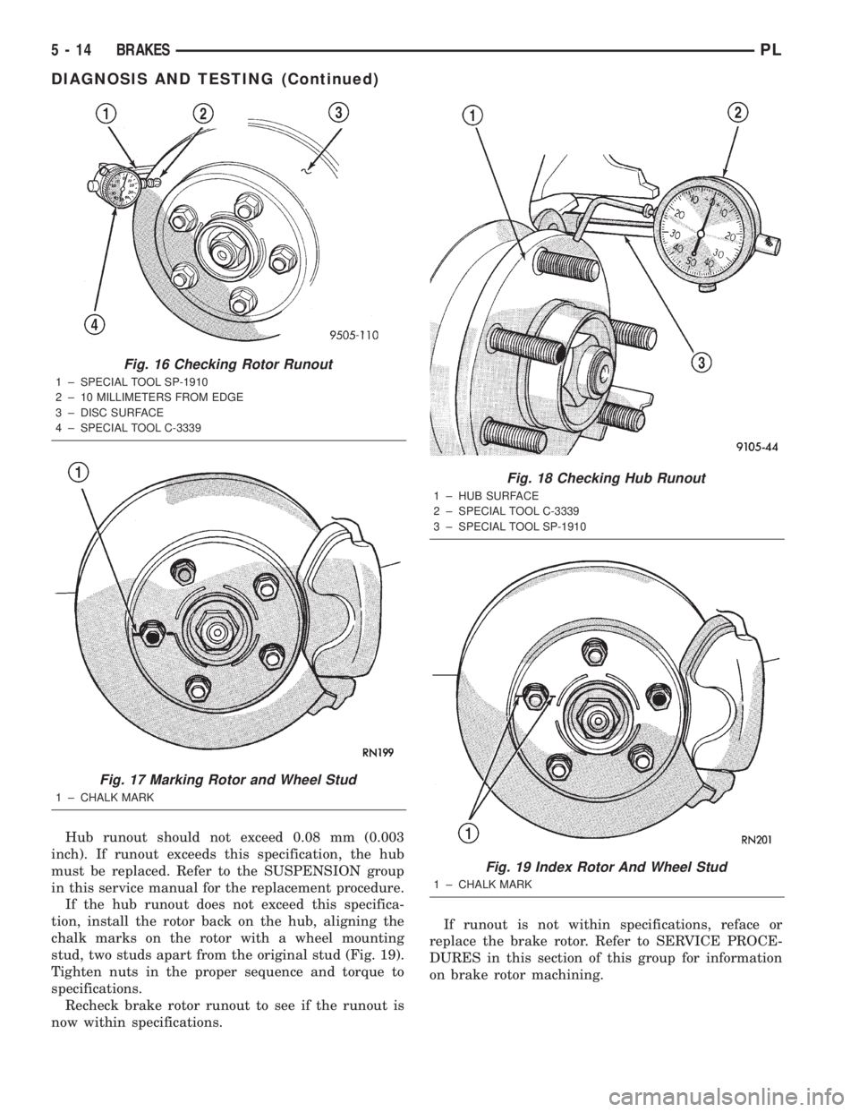
on steering arm. The dial indicator plunger should
contact braking surface of rotor approximately one
inch from edge of rotor (Fig. 16). Check lateral runout
on both sides of the rotor, marking the low and high
spots on both. Runout limits can be found in the table
at the end of this brake rotor information.
If runout is in excess of the specification, check the
lateral runout of the hub face. Before removing the
rotor from the hub, place a chalk mark across both
the rotor and the one wheel stud closest to where the
high runout measurement was taken. This way, the
original mounting spot of the rotor on the hub is
indexed (Fig. 17).
Remove the rotor from the hub.
NOTE: Clean the hub face surface before checking
runout. This provides a clean surface to get an
accurate indicator reading.
Mount Dial Indicator, Special Tool C-3339, and
Mounting Adaptor, Special Tool SP-1910, to the steer-
ing knuckle. Position the indicator stem so it contacts
the hub face near the outer diameter. Care must be
taken to position stem outside of the stud circle, but
inside of the chamfer on the hub rim (Fig. 18).
Fig. 14 Minimum Brake Rotor Thickness Markings
(Typical)
1 ± ROTOR MINIMUM THICKNESS MARKING
2 ± ROTOR
Fig. 15 Checking Rotor For Thickness
1 ± CALIPER
PLBRAKES 5 - 13
DIAGNOSIS AND TESTING (Continued)
Page 93 of 1285
Hub runout should not exceed 0.08 mm (0.003
inch). If runout exceeds this specification, the hub
must be replaced. Refer to the SUSPENSION group
in this service manual for the replacement procedure.
If the hub runout does not exceed this specifica-
tion, install the rotor back on the hub, aligning the
chalk marks on the rotor with a wheel mounting
stud, two studs apart from the original stud (Fig. 19).
Tighten nuts in the proper sequence and torque to
specifications.
Recheck brake rotor runout to see if the runout is
now within specifications.If runout is not within specifications, reface or
replace the brake rotor. Refer to SERVICE PROCE-
DURES in this section of this group for information
on brake rotor machining.
Fig. 16 Checking Rotor Runout
1 ± SPECIAL TOOL SP-1910
2 ± 10 MILLIMETERS FROM EDGE
3 ± DISC SURFACE
4 ± SPECIAL TOOL C-3339
Fig. 17 Marking Rotor and Wheel Stud
1 ± CHALK MARK
Fig. 18 Checking Hub Runout
1 ± HUB SURFACE
2 ± SPECIAL TOOL C-3339
3 ± SPECIAL TOOL SP-1910
Fig. 19 Index Rotor And Wheel Stud
1 ± CHALK MARK
5 - 14 BRAKESPL
DIAGNOSIS AND TESTING (Continued)
Page 104 of 1285
(10) If the vehicle is equipped with antilock
brakes, carefully push the power brake booster for-
ward until the booster contacts the ABS ICU mount-
ing bracket.
(11) If the vehicle does not have antilock brakes,
carefully push the power brake booster forward one
to two inches being careful not to stretch the brake
lines from the master cylinder to the brakes.
(12) Remove the two nuts fastening the brake
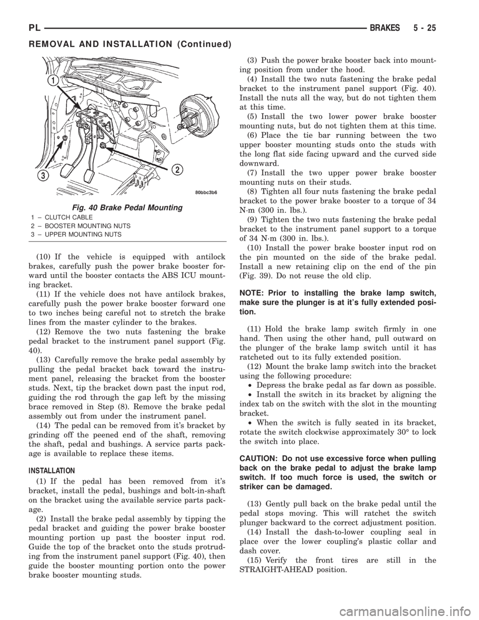
pedal bracket to the instrument panel support (Fig.
40).
(13) Carefully remove the brake pedal assembly by
pulling the pedal bracket back toward the instru-
ment panel, releasing the bracket from the booster
studs. Next, tip the bracket down past the input rod,
guiding the rod through the gap left by the missing
brace removed in Step (8). Remove the brake pedal
assembly out from under the instrument panel.
(14) The pedal can be removed from it's bracket by
grinding off the peened end of the shaft, removing
the shaft, pedal and bushings. A service parts pack-
age is available to replace these items.
INSTALLATION
(1) If the pedal has been removed from it's
bracket, install the pedal, bushings and bolt-in-shaft
on the bracket using the available service parts pack-
age.
(2) Install the brake pedal assembly by tipping the
pedal bracket and guiding the power brake booster
mounting portion up past the booster input rod.
Guide the top of the bracket onto the studs protrud-
ing from the instrument panel support (Fig. 40), then
guide the booster mounting portion onto the power
brake booster mounting studs.(3) Push the power brake booster back into mount-
ing position from under the hood.
(4) Install the two nuts fastening the brake pedal
bracket to the instrument panel support (Fig. 40).
Install the nuts all the way, but do not tighten them
at this time.
(5) Install the two lower power brake booster
mounting nuts, but do not tighten them at this time.
(6) Place the tie bar running between the two
upper booster mounting studs onto the studs with
the long flat side facing upward and the curved side
downward.
(7) Install the two upper power brake booster
mounting nuts on their studs.
(8) Tighten all four nuts fastening the brake pedal
bracket to the power brake booster to a torque of 34
N´m (300 in. lbs.).
(9) Tighten the two nuts fastening the brake pedal
bracket to the instrument panel support to a torque
of 34 N´m (300 in. lbs.).
(10) Install the power brake booster input rod on
the pin mounted on the side of the brake pedal.
Install a new retaining clip on the end of the pin
(Fig. 39). Do not reuse the old clip.
NOTE: Prior to installing the brake lamp switch,
make sure the plunger is at it's fully extended posi-
tion.
(11) Hold the brake lamp switch firmly in one
hand. Then using the other hand, pull outward on
the plunger of the brake lamp switch until it has
ratcheted out to its fully extended position.
(12) Mount the brake lamp switch into the bracket
using the following procedure:
²Depress the brake pedal as far down as possible.
²Install the switch in its bracket by aligning the
index tab on the switch with the slot in the mounting
bracket.
²When the switch is fully seated in its bracket,
rotate the switch clockwise approximately 30É to lock
the switch into place.
CAUTION: Do not use excessive force when pulling
back on the brake pedal to adjust the brake lamp
switch. If too much force is used, the switch or
striker can be damaged.
(13) Gently pull back on the brake pedal until the
pedal stops moving. This will ratchet the switch
plunger backward to the correct adjustment position.
(14) Install the dash-to-lower coupling seal in
place over the lower coupling's plastic collar and
dash cover.
(15) Verify the front tires are still in the
STRAIGHT-AHEAD position.
Fig. 40 Brake Pedal Mounting
1 ± CLUTCH CABLE
2 ± BOOSTER MOUNTING NUTS
3 ± UPPER MOUNTING NUTS
PLBRAKES 5 - 25
REMOVAL AND INSTALLATION (Continued)
Page 106 of 1285
(4) Install the power brake booster mounting nuts.
Tighten the four nuts fastening the brake pedal
bracket to the power brake booster to a torque of 34
N´m (300 in. lbs.).
(5) Tighten the two nuts fastening the brake pedal
bracket to the instrument panel support to a torque
of 34 N´m (300 in. lbs.).
(6) Connect the clutch cable to the clutch pedal
spacer on the pedal (Fig. 41).
(7) Connect the wiring harness connector going to
the clutch pedal switches (Fig. 42).
(8) Install the power brake booster input rod on
the pin mounted on the side of the brake pedal.
Install a new retaining clip on the end of the pin
(Fig. 39). Do not reuse the old clip.
NOTE: Prior to installing the brake lamp switch,
make sure the plunger is at it's fully extended posi-
tion.
(9) Hold the brake lamp switch firmly in one hand.
Then using the other hand, pull outward on the
plunger of the brake lamp switch until it has ratch-
eted out to its fully extended position.
(10) Mount the brake lamp switch into the bracket
using the following procedure:
²Depress the brake pedal as far down as possible.
²Install the switch in its bracket by aligning the
index tab on the switch with the slot in the mounting
bracket.
²When the switch is fully seated in its bracket,
rotate the switch clockwise approximately 30É to lock
the switch into place.
CAUTION: Do not use excessive force when pulling
back on the brake pedal to adjust the brake lamp
switch. If too much force is used, the switch or
striker can be damaged.
(11) Gently pull back on the brake pedal until the
pedal stops moving. This will ratchet the switch
plunger backward to the correct adjustment position.
(12) Install the instrument panel. Refer to the
INSTRUMENT PANELS AND SYSTEMS group in
this service manual for the required procedure.
(13) Check the stop lamps to verify they are oper-
ating properly and not staying on when the pedal is
in the released position.
(14) Road test the vehicle to ensure proper opera-
tion of the brakes.
BRAKE LAMP SWITCH
REMOVAL
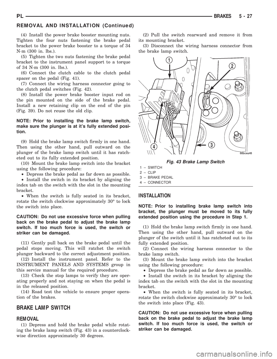
(1) Depress and hold the brake pedal while rotat-
ing the brake lamp switch (Fig. 43) in a counterclock-
wise direction approximately 30 degrees.(2) Pull the switch rearward and remove it from
its mounting bracket.
(3) Disconnect the wiring harness connector from
the brake lamp switch.
INSTALLATION
NOTE: Prior to installing brake lamp switch into
bracket, the plunger must be moved to its fully
extended position using the procedure in Step 1.
(1) Hold the brake lamp switch firmly in one hand.
Then using the other hand, pull outward on the
plunger of the switch until it has ratcheted out to its
fully extended position.
(2) Connect the wiring harness connector to the
brake lamp switch.
(3) Mount the brake lamp switch into the bracket
using the following procedure:
²Depress the brake pedal as far down as possible.
²Install the switch in its bracket by aligning the
index tab on the switch with the slot in the mounting
bracket.
²When the switch is fully seated in its bracket,
rotate the switch clockwise approximately 30É to lock
the switch into place (Fig. 43).
CAUTION: Do not use excessive force when pulling
back on the brake pedal to adjust the brake lamp
switch. If too much force is used, the switch or
striker can be damaged.
Fig. 43 Brake Lamp Switch
1 ± SWITCH
2 ± CLIP
3 ± BRAKE PEDAL
4 ± CONNECTOR
PLBRAKES 5 - 27
REMOVAL AND INSTALLATION (Continued)
Page 140 of 1285
WHEEL CYLINDER
With the brake drums removed, inspect the wheel
cylinder boots for evidence of a brake fluid leak.
Visually check the boots for cuts, tears, or heat
cracks. If any of these conditions exist, the wheel cyl-
inders should be completely cleaned, inspected and
new parts installed.
If a wheel cylinder is leaking and the brake lining
material is saturated with brake fluid, the brake
shoes must be replaced.
ADJUSTMENTS
BRAKE LAMP SWITCH
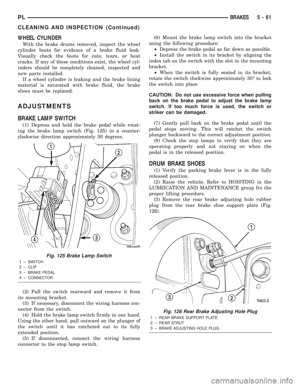
(1) Depress and hold the brake pedal while rotat-
ing the brake lamp switch (Fig. 125) in a counter-
clockwise direction approximately 30 degrees.
(2) Pull the switch rearward and remove it from
its mounting bracket.
(3) If necessary, disconnect the wiring harness con-
nector from the switch.
(4) Hold the brake lamp switch firmly in one hand.
Using the other hand, pull outward on the plunger of
the switch until it has ratcheted out to its fully
extended position.
(5) If disconnected, connect the wiring harness
connector to the stop lamp switch.(6) Mount the brake lamp switch into the bracket
using the following procedure:
²Depress the brake pedal as far down as possible.
²Install the switch in its bracket by aligning the
index tab on the switch with the slot in the mounting
bracket.
²When the switch is fully seated in its bracket,
rotate the switch clockwise approximately 30É to lock
the switch into place.
CAUTION: Do not use excessive force when pulling
back on the brake pedal to adjust the brake lamp
switch. If too much force is used, the switch or
striker can be damaged.
(7) Gently pull back on the brake pedal until the
pedal stops moving. This will ratchet the switch
plunger backward to the correct adjustment position.
(8) Check the stop lamps to verify that they are
operating properly and not staying on when the
pedal is in the released position.
DRUM BRAKE SHOES
(1) Verify the parking brake lever is in the fully
released position.
(2) Raise the vehicle. Refer to HOISTING in the
LUBRICATION AND MAINTENANCE group fro the
proper lifting procedure.
(3) Remove the rear brake adjusting hole rubber
plug from the rear brake shoe support plate (Fig.
126).
Fig. 125 Brake Lamp Switch
1 ± SWITCH
2 ± CLIP
3 ± BRAKE PEDAL
4 ± CONNECTOR
Fig. 126 Rear Brake Adjusting Hole Plug
1 ± REAR BRAKE SUPPORT PLATE
2 ± REAR STRUT
3 ± BRAKE ADJUSTING HOLE PLUG
PLBRAKES 5 - 61
CLEANING AND INSPECTION (Continued)
Page 184 of 1285
RADIATOR HOSES AND CLAMPS
WARNING: IF VEHICLE HAS BEEN RUN RECENTLY,
WAIT 15 MINUTES BEFORE WORKING ON VEHI-
CLE. RELIEVE PRESSURE BY PLACING A SHOP
TOWEL OVER THE CAP AND WITHOUT PUSHING
DOWN ROTATE IT COUNTERCLOCKWISE TO THE
FIRST STOP. ALLOW FLUIDS TO ESCAPE
THROUGH THE OVERFLOW TUBE AND WHEN THE
SYSTEM STOPS PUSHING OUT COOLANT AND
STEAM AND THE PRESSURE DROPS CONTINUE
SERVICE.
WARNING: CONSTANT TENSION HOSE CLAMPS
ARE USED ON MOST COOLING SYSTEM HOSES.
WHEN REMOVING OR INSTALLING, USE ONLY
TOOLS DESIGNED FOR SERVICING THIS TYPE OF
CLAMP. ALWAYS WEAR SAFETY GLASSES WHEN
SERVICING CONSTANT TENSION CLAMPS.
CAUTION: A number or letter is stamped into the
tongue of constant tension clamps. If replacement
is necessary, use only a original equipment clamp
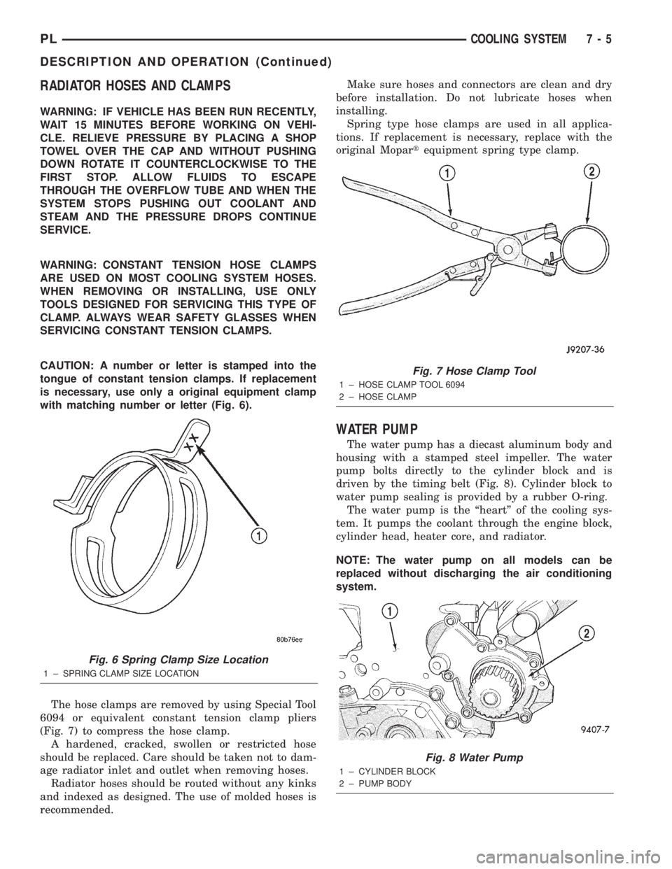
with matching number or letter (Fig. 6).
The hose clamps are removed by using Special Tool
6094 or equivalent constant tension clamp pliers
(Fig. 7) to compress the hose clamp.
A hardened, cracked, swollen or restricted hose
should be replaced. Care should be taken not to dam-
age radiator inlet and outlet when removing hoses.
Radiator hoses should be routed without any kinks
and indexed as designed. The use of molded hoses is
recommended.Make sure hoses and connectors are clean and dry
before installation. Do not lubricate hoses when
installing.
Spring type hose clamps are used in all applica-
tions. If replacement is necessary, replace with the
original Mopartequipment spring type clamp.
WATER PUMP
The water pump has a diecast aluminum body and
housing with a stamped steel impeller. The water
pump bolts directly to the cylinder block and is
driven by the timing belt (Fig. 8). Cylinder block to
water pump sealing is provided by a rubber O-ring.
The water pump is the ªheartº of the cooling sys-
tem. It pumps the coolant through the engine block,
cylinder head, heater core, and radiator.
NOTE: The water pump on all models can be
replaced without discharging the air conditioning
system.
Fig. 6 Spring Clamp Size Location
1 ± SPRING CLAMP SIZE LOCATION
Fig. 7 Hose Clamp Tool
1 ± HOSE CLAMP TOOL 6094
2 ± HOSE CLAMP
Fig. 8 Water Pump
1 ± CYLINDER BLOCK
2 ± PUMP BODY
PLCOOLING SYSTEM 7 - 5
DESCRIPTION AND OPERATION (Continued)
Page 239 of 1285
The PCM sends approximately 8 volts to the Hall-
effect sensor. This voltage is required to operate the
Hall-effect chip and the electronics inside the sensor.
A ground for the sensor is provided through the sen-
sor return circuit. The input to the PCM occurs on a
5 volt output reference circuit.
The notches generate pulses from high to low in
the crankshaft position sensor output voltage. When
a metal portion of the counterweight aligns with the
crankshaft position sensor, the sensor output voltage
goes low (less than 0.5 volts). When a notch aligns
with the sensor, voltage goes high (5.0 volts). As a
group of notches pass under the sensor, the output
voltage switches from low (metal) to high (notch)
then back to low.
If available, an oscilloscope can display the square
wave patterns of each voltage pulses. From the width
of the output voltage pulses, the PCM calculates
engine speed. The width of the pulses represent the
amount of time the output voltage stays high before
switching back to low. The period of time the sensor
output voltage stays high before switching back to
low is referred to as pulse width. The faster the
engine is operating, the smaller the pulse width on
the oscilloscope.
By counting the pulses and referencing the pulse
from the 60 degree signature notch, the PCM calcu-
lates crankshaft angle (position). In each group of
timing reference notches, the first notch represents
69 degrees before top dead center (BTDC). The sec-
ond notch represents 49 degrees BTDC. The third
notch represents 29 degrees. The last notch in each
set represents 9 degrees before top dead center
(TDC).
The timing reference notches are machined at 20É
increments. From the voltage pulse width the PCM
tells the difference between the timing reference
notches and the 60 degree signature notch. The 60
degree signature notch produces a longer pulse width
than the smaller timing reference notches. If the
camshaft position sensor input switches from high to
low when the 60 degree signature notch passes under
the crankshaft position sensor, the PCM knows cylin-
der number one is the next cylinder at TDC.CAMSHAFT POSITION SENSORÐPCM INPUT
DESCRIPTION
The camshaft position sensor attaches to the rear
of the cylinder head. The PCM determines fuel injec-
tion synchronization and cylinder identification from
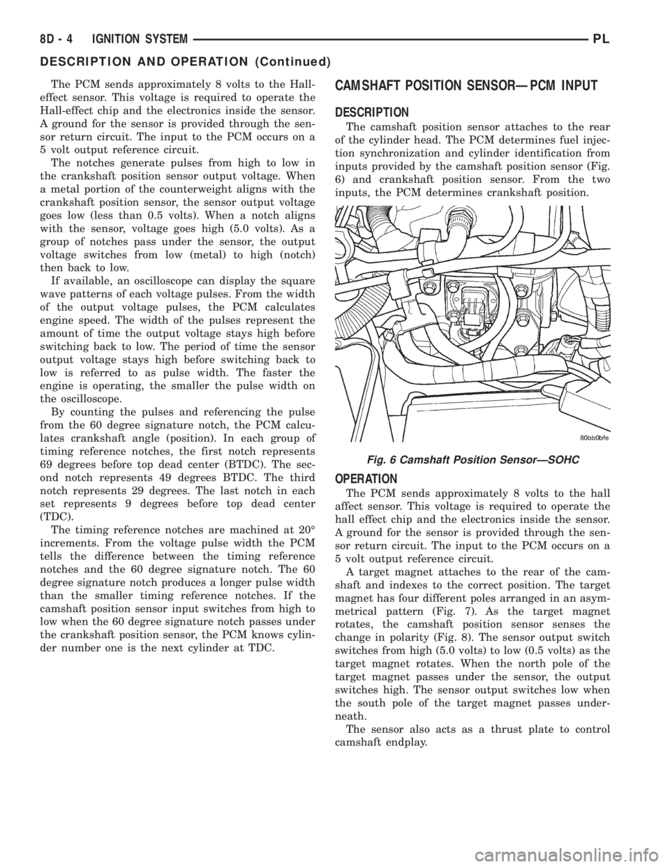
inputs provided by the camshaft position sensor (Fig.
6) and crankshaft position sensor. From the two
inputs, the PCM determines crankshaft position.
OPERATION
The PCM sends approximately 8 volts to the hall
affect sensor. This voltage is required to operate the
hall effect chip and the electronics inside the sensor.
A ground for the sensor is provided through the sen-
sor return circuit. The input to the PCM occurs on a
5 volt output reference circuit.
A target magnet attaches to the rear of the cam-
shaft and indexes to the correct position. The target
magnet has four different poles arranged in an asym-
metrical pattern (Fig. 7). As the target magnet
rotates, the camshaft position sensor senses the
change in polarity (Fig. 8). The sensor output switch
switches from high (5.0 volts) to low (0.5 volts) as the
target magnet rotates. When the north pole of the
target magnet passes under the sensor, the output
switches high. The sensor output switches low when
the south pole of the target magnet passes under-
neath.
The sensor also acts as a thrust plate to control
camshaft endplay.
Fig. 6 Camshaft Position SensorÐSOHC
8D - 4 IGNITION SYSTEMPL
DESCRIPTION AND OPERATION (Continued)
Page 253 of 1285
(6) Set base aside and remove base mount ring.
INSTALLATION
(1) Position mount ring to the instrument panel
and feed the wires through ring. Index the cap and
the mount ring with the index tab at 9 o'clock to the
key in the instrument panel. Install the ring.
(2) Connect wires to base. Orient base alignment
rib at 11 o'clock to mate the groove in mount ring at
the same location
(3) Push base into the bezel till it locks.
(4) Install cigar lighter cap and check operation of
element.
GLOVE BOX DOOR/BIN
REMOVAL
(1) Open front passenger door.
(2) Remove three glove box door hinge screws.
(3) Open glove box and remove assembly from
vehicle.
(4) Remove eight screws retaining glove box door
to bin assembly.
(5) Separate glove box door from bin and remove.
INSTALLATION
For installation, reverse the above procedures.
GLOVE BOX DOOR/BIN
REMOVAL
(1) Open front passenger door.
(2) Remove three glove box door hinge screws.
(3) Open glove box and remove assembly from
vehicle.
(4) Remove eight screws retaining glove box door
to bin assembly.(5) Separate glove box door from bin and remove.
INSTALLATION
For installation, reverse the above procedures.
GLOVE BOX SWITCH/LAMP
REMOVAL
(1) Disconnect and isolate the battery negative
cable (Fig. 6).
(2) Open the glove box and push the glove box
sides inward allowing the door bumpers to clear and
the box to tip forward.
(3) Reach inside the opening and squeeze the
lamp/switch retainers until they are disengage.
(4) Pull the switch/lamp rearward and remove it.
Replace the lamp. To replace the switch disconnect
wire and replace the switch.
INSTALLATION
For installation, reverse the above procedures.
INSTRUMENT CLUSTER
CAUTION: The Instrument Cluster MUST be stored
in a face up position or damage will occur to the
gauge operation.
REMOVAL
(1) Disconnect and isolate the battery negative
cable (Fig. 6).
(2) Remove both left and right A-Pillar trim covers.
(3) Remove the instrument panel top cover.
(4) Remove cluster bezel.
(5) Remove the four screws attaching cluster hous-
ing to the base panel.
(6) Pull the cluster rearward to disconnect from
base panel.
(7) Remove the cluster assembly.
INSTALLATION
For installation, reverse the above procedures.
INSTRUMENT CLUSTER BEZEL
REMOVAL
(1) Remove instrument panel top cover. Refer to
Instrument Panel Top Cover Removal and Installa-
tion in this section.
(2) Using a trim stick (special tool #C-4755), gently
pry up on the cluster bezel and remove from vehicle.
INSTALLATION
For installation, reverse the above procedures.
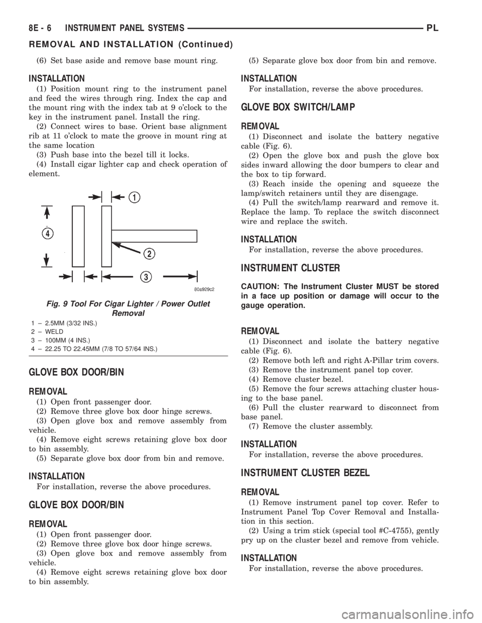
Fig. 9 Tool For Cigar Lighter / Power Outlet
Removal
1 ± 2.5MM (3/32 INS.)
2 ± WELD
3 ± 100MM (4 INS.)
4 ± 22.25 TO 22.45MM (7/8 TO 57/64 INS.)
8E - 6 INSTRUMENT PANEL SYSTEMSPL
REMOVAL AND INSTALLATION (Continued)