2000 DODGE NEON oil level
[x] Cancel search: oil levelPage 4 of 1285
MAINTENANCE SCHEDULES
TABLE OF CONTENTS
page page
DESCRIPTION AND OPERATION
MAINTENANCE SCHEDULES................3
SPECIFICATIONS
UNSCHEDULED INSPECTION................3SCHEDULE ± A...........................3
SCHEDULE ± B...........................4
DESCRIPTION AND OPERATION
MAINTENANCE SCHEDULES
There are two maintenance schedules that show
proper service for your vehicle.
First is Schedule ±A. It lists all the scheduled
maintenance to be performed under ªnormalº operat-
ing conditions.
Second is Schedule ±B. It is a schedule for vehi-
cles that are operated under the following conditions:
²Frequent short trip driving less than 5 miles (8
km)
²Frequent driving in dusty conditions
²Extensive idling
²More than 50% of the driving is at sustained
high speeds during hot weather, above 90É F (32É C)
SPECIFICATIONS
UNSCHEDULED INSPECTION
At Each Stop For Fuel
²Check engine oil level and add as required.
²Check windshield washer solvent and add as
required.
Once A Month
²Check tire pressure and look for unusual wear
or damage.
²Inspect the battery and clean and tighten termi-
nals as required.
²Check fluid levels of coolant reservoir, brake
master cylinder, power steering and transmission.
Add fluid as required.
²Check all lights and all other electrical items for
correct operation.
At Each Oil Change
²Inspect the exhaust system.
²Inspect brake hoses.
²Inspect the CV joints and front suspension com-
ponent boots and seals.²Rotate the tires at each oil change interval
shown on Schedule ± A (7,500 miles - 12 000 km) or
every other interval on Schedule ± B (6,000 miles -
10 000 km).
²Check the engine coolant level, hoses, and
clamps.
If mileage is less than 7,500 miles (12 000 km)
yearly, replace the engine oil filter at each oil change.
EMISSION CONTROL SYSTEM MAINTENANCE
The scheduled emission maintenance listed inbold
typeon the Maintenance Schedules, must be done at
the mileage specified to assure the continued proper
functioning of the emission control system. These,
and all other maintenance services included in this
manual, should be done to provide the best vehicle
performance and reliability. More frequent mainte-
nance may be needed for vehicles in severe operating
conditions such as dusty areas and very short trip
driving.
FLUID FILL POINTS AND LUBRICATION
LOCATIONS
The fluid fill/check locations and lubrication loca-
tions are located in each applicable group.
SCHEDULE ± A
7,500 Miles (12 000 km) or at 6 months
²Change the engine oil.
²Replace the engine oil filter.
15,000 Miles (24 000 km) or at 12 months
²Change the engine oil.
²Replace the engine oil filter.
²Adjust the drive belt tension.
22,500 Miles (36 000 km) or at 18 months
²Change the engine oil.
²Replace the engine oil filter.
²Inspect the front brake pads and rear brake lin-
ings.
PLLUBRICATION AND MAINTENANCE 0 - 3
Page 16 of 1285
SERVICE PROCEDURES
CURB HEIGHT MEASUREMENT
The wheel alignment is to be checked and all align-
ment adjustments made with the vehicle at its
required curb height specification.
Vehicle height is to be checked with the vehicle on
a flat, level surface, preferably a vehicle alignment
rack. The tires are to be inflated to the recommended
pressure. All tires are to be the same size as stan-
dard equipment. Vehicle height is checked with the
fuel tank full of fuel, and no passenger or luggage
compartment load.
Vehicle height is not adjustable. If the measure-
ment is not within specifications, inspect the vehicle
for bent or weak suspension components. Compare
the parts tag on the suspect coil spring(s) to the
parts book and the vehicle sales code, checking for a
match. Once removed from the vehicle, compare thecoil spring height to a correct new or known good coil
spring. The heights should vary if the suspect spring
is weak.
NOTE: Prior to reading the curb height measure-
ment, the front an rear of the vehicle should be
jounced. Induce jounce by grasping the center of
the rear, then front bumper (or fascia) and jouncing
the vehicle an equal number of times. Release the
bumper at the bottom of the jounce cycle.
(1) Measure from the inboard edge of the wheel
opening fender lip directly above the wheel center
(spindle), to the floor or alignment rack surface.
(2) When measuring, maximum left-to-right differ-
ential is not to exceed 10 mm (0.39 in.).
(3) Compare the measurements to specifications
listed in the following CURB HEIGHT SPECIFICA-
TIONS chart.
CURB HEIGHT SPECIFICATIONS
VEHICLE FRONT REAR
ALL NEON672 mm68 mm 679 mm68mm
26.46 in.60.32 in. 26.73 in.60.32 in.
WHEEL ALIGNMENT
PRE-WHEEL ALIGNMENT VEHICLE INSPECTION
CAUTION: If during the inspection the front sus-
pension crossmember shows any sign of impact
damage, the steering column lower coupling must
be inspected. Refer to DIAGNOSIS AND TESTING in
the STEERING group in this service manual.
Before any attempt is made to change or correct
the wheel alignment, the following inspection and
necessary corrections must be made to the vehicle to
ensure proper alignment.
(1) Be sure the fuel tank is full of fuel. If the fuel
tank is not full, the reduction in weight will affect
the curb height of the vehicle and the alignment
specifications.
(2) The passenger and luggage compartments of
the vehicle should be free of any load that is not fac-
tory equipment.
(3) Check the tires on the vehicle. The tires are to
be inflated to the recommended air pressure. All tires
must be the same size and in good condition with
approximately the same tread wear.
(4) Check the front tire and wheel assemblies for
excessive radial runout.(5) Inspect all suspension component fasteners for
looseness and torque.
(6) Inspect the lower front ball joints and all steer-
ing linkage for looseness and any sign of wear or
damage.
(7) Inspect the rubber bushings on all the suspen-
sion components for signs of wear or deterioration. If
any bushings show signs of wear or deterioration,
they should be replaced prior to aligning the vehicle.
WHEEL ALIGNMENT SETUP
(1) Position the vehicle on an alignment rack.
(2) Install all required alignment equipment on
the vehicle, per the alignment equipment manufac-
turer's instructions. On this vehicle, a four-wheel
alignment is recommended.
NOTE: Prior to reading the vehicle's alignment
readouts, the front and rear of vehicle should be
jounced. Induce jounce (rear first, then front) by
grasping the center of the bumper and jouncing
each end of vehicle an equal number of times. The
bumper should always be released when vehicle is
at the bottom of the jounce cycle.
(3) Read the vehicle's current front and rear align-
ment settings. Compare the vehicle's current align-
ment settings to the vehicle specifications for camber,
caster and toe-in. Refer to WHEEL ALIGNMENT
PLSUSPENSION 2 - 5
Page 58 of 1285
nuts are torqued to half specification. Repeat the
tightening sequence, this time, to full specified
torque of 135 N´m (100 ft. lbs.).
(8) Lower the vehicle to ground level.
(9) Set the rear toe on the vehicle to the required
specification if necessary. Refer to WHEEL ALIGN-
MENT in this service manual group.
STABILIZER BAR (REAR)
NOTE: Before proceeding with this procedure,
review SERVICE WARNINGS AND CAUTIONS at the
beginning of REMOVAL AND INSTALLATION in this
section.
REMOVAL
(1) Raise the vehicle. Refer to HOISTING in the
LUBRICATION AND MAINTENANCE group for the
proper lifting procedure.
(2) Remove both rear wheel and tire assemblies
from the vehicle.
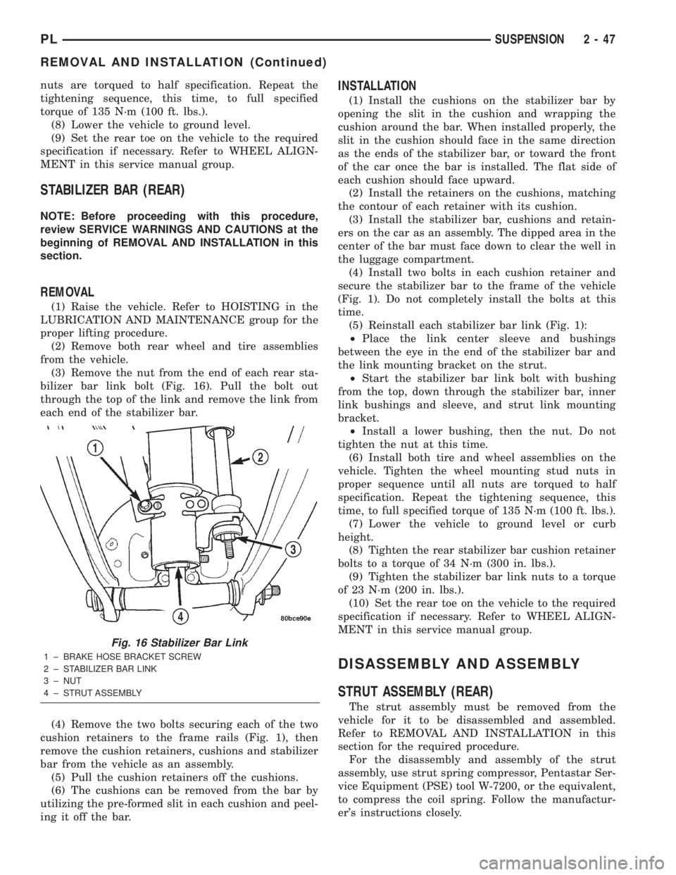
(3) Remove the nut from the end of each rear sta-
bilizer bar link bolt (Fig. 16). Pull the bolt out
through the top of the link and remove the link from
each end of the stabilizer bar.
(4) Remove the two bolts securing each of the two
cushion retainers to the frame rails (Fig. 1), then
remove the cushion retainers, cushions and stabilizer
bar from the vehicle as an assembly.
(5) Pull the cushion retainers off the cushions.
(6) The cushions can be removed from the bar by
utilizing the pre-formed slit in each cushion and peel-
ing it off the bar.
INSTALLATION
(1) Install the cushions on the stabilizer bar by
opening the slit in the cushion and wrapping the
cushion around the bar. When installed properly, the
slit in the cushion should face in the same direction
as the ends of the stabilizer bar, or toward the front
of the car once the bar is installed. The flat side of
each cushion should face upward.
(2) Install the retainers on the cushions, matching
the contour of each retainer with its cushion.
(3) Install the stabilizer bar, cushions and retain-
ers on the car as an assembly. The dipped area in the
center of the bar must face down to clear the well in
the luggage compartment.
(4) Install two bolts in each cushion retainer and
secure the stabilizer bar to the frame of the vehicle
(Fig. 1). Do not completely install the bolts at this
time.
(5) Reinstall each stabilizer bar link (Fig. 1):
²Place the link center sleeve and bushings
between the eye in the end of the stabilizer bar and
the link mounting bracket on the strut.
²Start the stabilizer bar link bolt with bushing
from the top, down through the stabilizer bar, inner
link bushings and sleeve, and strut link mounting
bracket.
²Install a lower bushing, then the nut. Do not
tighten the nut at this time.
(6) Install both tire and wheel assemblies on the
vehicle. Tighten the wheel mounting stud nuts in
proper sequence until all nuts are torqued to half
specification. Repeat the tightening sequence, this
time, to full specified torque of 135 N´m (100 ft. lbs.).
(7) Lower the vehicle to ground level or curb
height.
(8) Tighten the rear stabilizer bar cushion retainer
bolts to a torque of 34 N´m (300 in. lbs.).
(9) Tighten the stabilizer bar link nuts to a torque
of 23 N´m (200 in. lbs.).
(10) Set the rear toe on the vehicle to the required
specification if necessary. Refer to WHEEL ALIGN-
MENT in this service manual group.
DISASSEMBLY AND ASSEMBLY
STRUT ASSEMBLY (REAR)
The strut assembly must be removed from the
vehicle for it to be disassembled and assembled.
Refer to REMOVAL AND INSTALLATION in this
section for the required procedure.
For the disassembly and assembly of the strut
assembly, use strut spring compressor, Pentastar Ser-
vice Equipment (PSE) tool W-7200, or the equivalent,
to compress the coil spring. Follow the manufactur-
er's instructions closely.
Fig. 16 Stabilizer Bar Link
1 ± BRAKE HOSE BRACKET SCREW
2 ± STABILIZER BAR LINK
3 ± NUT
4 ± STRUT ASSEMBLY
PLSUSPENSION 2 - 47
REMOVAL AND INSTALLATION (Continued)
Page 96 of 1285
following this procedure. If the inlet gauge pressure
overshoots its target pressure when the pedal is
depressed, release the brake pedal, relieving the
pressure in the system, before reapplying the pedal
to reach the target pressure at the inlet gauge. This
is necessary to get an accurate reading of the outlet
pressure.
(10) Once inlet pressure has been achieved, check
the pressure reading on the proportioning valve out-
let gauge. If the proportioning valve outlet pressure
does not agree with value shown in the table, replace
the proportioning valve. If proportioning valve is
within pressure specifications, the valve is good and
does not require replacement.(11)Reinstall the brake holding tool on the brake
pedal and remove the test equipment from the vehicle.
(12) Remove the tools from the proportioning
valve.
(13) Install the proportioning valve in the master
cylinder and hand tighten until the proportioning
valve is fully installed and its O-ring seal is seated
into the master cylinder. Torque the proportioning
valve to 40 N´m (30 ft. lbs.).
(14) Install the brake tube on the proportioning
valve. Torque the tube nut to 17 N´m (145 in. lbs.).
(15) Bleed the affected brake line. See BASE
BRAKE BLEEDING in this section of this service
manual group.
BRAKE PROPORTIONING VALVE APPLICATIONS AND PRESSURE SPECIFICATIONS
Sales
CodeBrake System Type Split Point Slope IdentificationInlet
PressureOutlet Pressure
BRA 14º Disc/Drum 300 psi 0.34 Black Band 1000 psi 550-650 psi
BRD 14º Disc/Disc 400 psi 0.43 Bar Code Band 1000 psi 600-700 psi
BRAKE FLUID CONTAMINATION
Indications of fluid contamination are swollen or
deteriorated rubber parts. Swelling indicates the
presence of petroleum in the brake fluid.
To test for contamination, put a small amount of
drained brake fluid in clear glass jar. If the fluid sep-
arates into layers, there is mineral oil or other fluid
contamination of the brake fluid.
If the brake fluid is contaminated, drain and thor-
oughly flush the brake system. Replace all the rubber
parts or components containing rubber coming into
contact with the brake fluid including: the master
cylinder; proportioning valves; caliper seals; wheel
cylinder seals; ABS hydraulic control unit; and all
hydraulic fluid hoses.
SERVICE PROCEDURES
BRAKE FLUID LEVEL CHECKING
Brake fluid level should be checked a minimum of
twice a year.
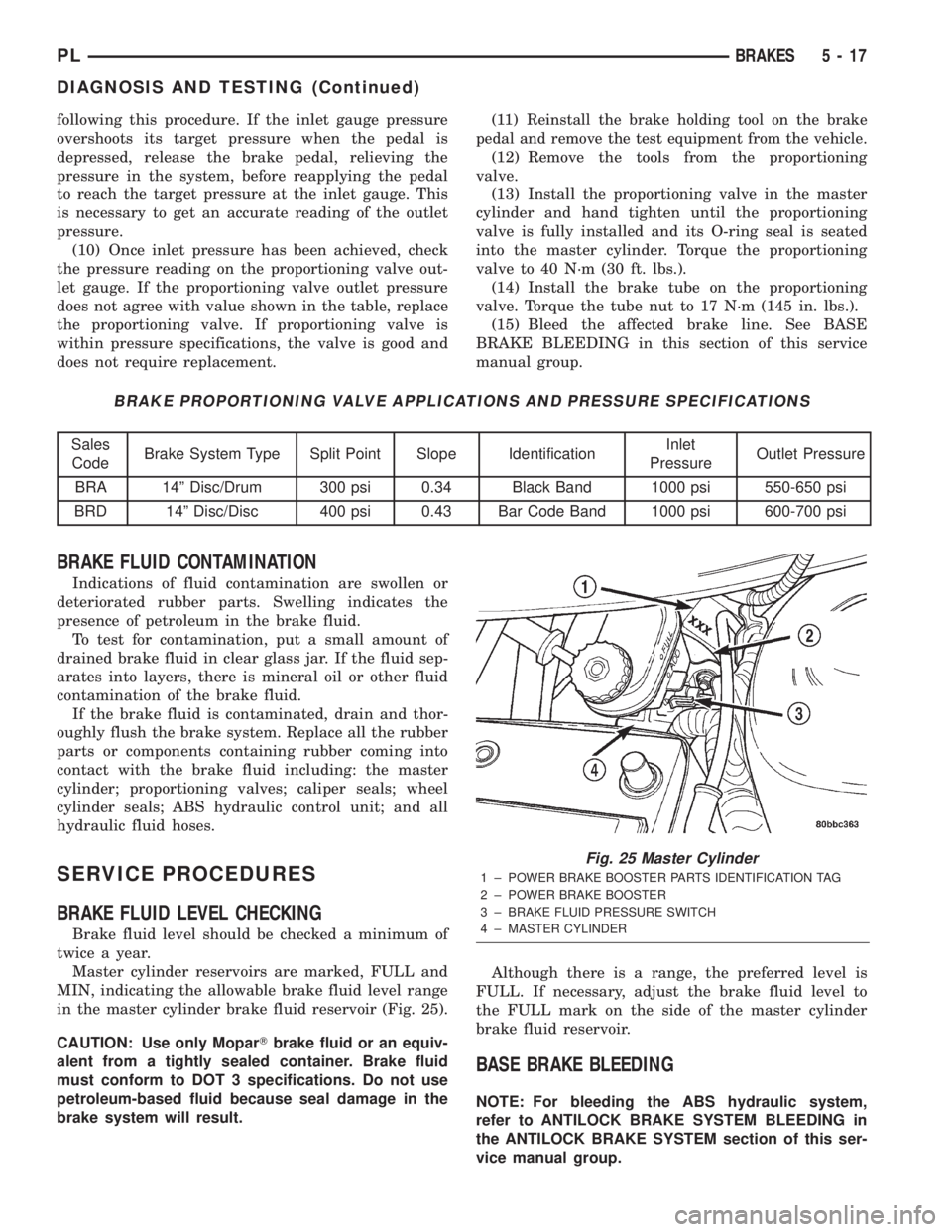
Master cylinder reservoirs are marked, FULL and
MIN, indicating the allowable brake fluid level range
in the master cylinder brake fluid reservoir (Fig. 25).
CAUTION: Use only MoparTbrake fluid or an equiv-
alent from a tightly sealed container. Brake fluid
must conform to DOT 3 specifications. Do not use
petroleum-based fluid because seal damage in the
brake system will result.Although there is a range, the preferred level is
FULL. If necessary, adjust the brake fluid level to
the FULL mark on the side of the master cylinder
brake fluid reservoir.
BASE BRAKE BLEEDING
NOTE: For bleeding the ABS hydraulic system,
refer to ANTILOCK BRAKE SYSTEM BLEEDING in
the ANTILOCK BRAKE SYSTEM section of this ser-
vice manual group.
Fig. 25 Master Cylinder
1 ± POWER BRAKE BOOSTER PARTS IDENTIFICATION TAG
2 ± POWER BRAKE BOOSTER
3 ± BRAKE FLUID PRESSURE SWITCH
4 ± MASTER CYLINDER
PLBRAKES 5 - 17
DIAGNOSIS AND TESTING (Continued)
Page 180 of 1285
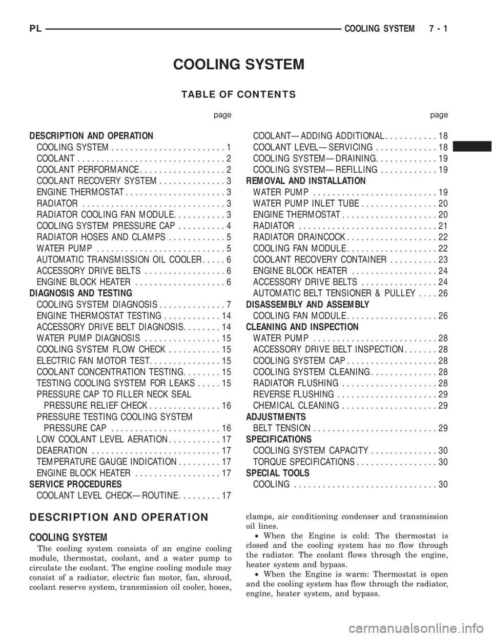
COOLING SYSTEM
TABLE OF CONTENTS
page page
DESCRIPTION AND OPERATION
COOLING SYSTEM........................1
COOLANT...............................2
COOLANT PERFORMANCE..................2
COOLANT RECOVERY SYSTEM..............3
ENGINE THERMOSTAT.....................3
RADIATOR..............................3
RADIATOR COOLING FAN MODULE...........3
COOLING SYSTEM PRESSURE CAP..........4
RADIATOR HOSES AND CLAMPS............5
WATER PUMP...........................5
AUTOMATIC TRANSMISSION OIL COOLER.....6
ACCESSORY DRIVE BELTS.................6
ENGINE BLOCK HEATER...................6
DIAGNOSIS AND TESTING
COOLING SYSTEM DIAGNOSIS..............7
ENGINE THERMOSTAT TESTING............14
ACCESSORY DRIVE BELT DIAGNOSIS........14
WATER PUMP DIAGNOSIS................15
COOLING SYSTEM FLOW CHECK...........15
ELECTRIC FAN MOTOR TEST...............15
COOLANT CONCENTRATION TESTING........15
TESTING COOLING SYSTEM FOR LEAKS.....15
PRESSURE CAP TO FILLER NECK SEAL
PRESSURE RELIEF CHECK...............16
PRESSURE TESTING COOLING SYSTEM
PRESSURE CAP.......................16
LOW COOLANT LEVEL AERATION...........17
DEAERATION...........................17
TEMPERATURE GAUGE INDICATION.........17
ENGINE BLOCK HEATER..................17
SERVICE PROCEDURES
COOLANT LEVEL CHECKÐROUTINE.........17COOLANTÐADDING ADDITIONAL...........18
COOLANT LEVELÐSERVICING.............18
COOLING SYSTEMÐDRAINING.............19
COOLING SYSTEMÐREFILLING............19
REMOVAL AND INSTALLATION
WATER PUMP..........................19
WATER PUMP INLET TUBE................20
ENGINE THERMOSTAT....................20
RADIATOR.............................21
RADIATOR DRAINCOCK...................22
COOLING FAN MODULE...................22
COOLANT RECOVERY CONTAINER..........23
ENGINE BLOCK HEATER..................24
ACCESSORY DRIVE BELTS................24
AUTOMATIC BELT TENSIONER & PULLEY....26
DISASSEMBLY AND ASSEMBLY
COOLING FAN MODULE...................26
CLEANING AND INSPECTION
WATER PUMP..........................28
ACCESSORY DRIVE BELT INSPECTION.......28
COOLING SYSTEM CAP...................28
COOLING SYSTEM CLEANING..............28
RADIATOR FLUSHING....................28
REVERSE FLUSHING.....................29
CHEMICAL CLEANING....................29
ADJUSTMENTS
BELT TENSION..........................29
SPECIFICATIONS
COOLING SYSTEM CAPACITY..............30
TORQUE SPECIFICATIONS.................30
SPECIAL TOOLS
COOLING..............................30
DESCRIPTION AND OPERATION
COOLING SYSTEM
The cooling system consists of an engine cooling
module, thermostat, coolant, and a water pump to
circulate the coolant. The engine cooling module may
consist of a radiator, electric fan motor, fan, shroud,
coolant reserve system, transmission oil cooler, hoses,clamps, air conditioning condenser and transmission
oil lines.
²When the Engine is cold: The thermostat is
closed and the cooling system has no flow through
the radiator. The coolant flows through the engine,
heater system and bypass.
²When the Engine is warm: Thermostat is open
and the cooling system has flow through the radiator,
engine, heater system, and bypass.
PLCOOLING SYSTEM 7 - 1
Page 182 of 1285
protection. MopartAntifreeze or the equivalent is
recommended for best engine cooling without corro-
sion. When mixed only to a freeze point of -37ÉC
(-35ÉF) to -59ÉC (-50ÉF). If it looses color or becomes
contaminated, drain, flush, and replace with fresh
properly mixed solution.
COOLANT RECOVERY SYSTEM
This system works in conjunction with the radiator
pressure cap to utilize thermal expansion and con-
traction of the coolant to keep the coolant free of
trapped air. The system provides space for expansion
and contraction. Also, the system provides a conve-
nient and safe method for checking and adjusting the
coolant level at atmospheric pressure without remov-
ing the pressure cap. It also provides some reserve
coolant to compensate for minor leaks and evapora-
tion or boiling losses. All vehicles are equipped with
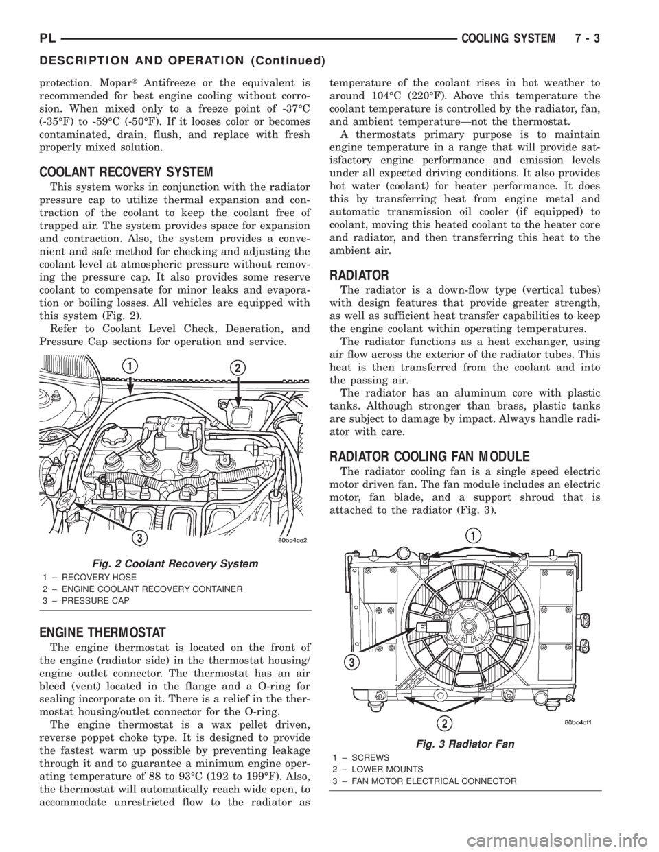
this system (Fig. 2).
Refer to Coolant Level Check, Deaeration, and
Pressure Cap sections for operation and service.
ENGINE THERMOSTAT
The engine thermostat is located on the front of
the engine (radiator side) in the thermostat housing/
engine outlet connector. The thermostat has an air
bleed (vent) located in the flange and a O-ring for
sealing incorporate on it. There is a relief in the ther-
mostat housing/outlet connector for the O-ring.
The engine thermostat is a wax pellet driven,
reverse poppet choke type. It is designed to provide
the fastest warm up possible by preventing leakage
through it and to guarantee a minimum engine oper-
ating temperature of 88 to 93ÉC (192 to 199ÉF). Also,
the thermostat will automatically reach wide open, to
accommodate unrestricted flow to the radiator astemperature of the coolant rises in hot weather to
around 104ÉC (220ÉF). Above this temperature the
coolant temperature is controlled by the radiator, fan,
and ambient temperatureÐnot the thermostat.
A thermostats primary purpose is to maintain
engine temperature in a range that will provide sat-
isfactory engine performance and emission levels
under all expected driving conditions. It also provides
hot water (coolant) for heater performance. It does
this by transferring heat from engine metal and
automatic transmission oil cooler (if equipped) to
coolant, moving this heated coolant to the heater core
and radiator, and then transferring this heat to the
ambient air.
RADIATOR
The radiator is a down-flow type (vertical tubes)
with design features that provide greater strength,
as well as sufficient heat transfer capabilities to keep
the engine coolant within operating temperatures.
The radiator functions as a heat exchanger, using
air flow across the exterior of the radiator tubes. This
heat is then transferred from the coolant and into
the passing air.
The radiator has an aluminum core with plastic
tanks. Although stronger than brass, plastic tanks
are subject to damage by impact. Always handle radi-
ator with care.
RADIATOR COOLING FAN MODULE
The radiator cooling fan is a single speed electric
motor driven fan. The fan module includes an electric
motor, fan blade, and a support shroud that is
attached to the radiator (Fig. 3).
Fig. 2 Coolant Recovery System
1 ± RECOVERY HOSE
2 ± ENGINE COOLANT RECOVERY CONTAINER
3 ± PRESSURE CAP
Fig. 3 Radiator Fan
1 ± SCREWS
2 ± LOWER MOUNTS
3 ± FAN MOTOR ELECTRICAL CONNECTOR
PLCOOLING SYSTEM 7 - 3
DESCRIPTION AND OPERATION (Continued)
Page 186 of 1285
DIAGNOSIS AND TESTING
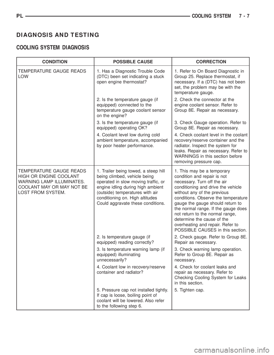
COOLING SYSTEM DIAGNOSIS
CONDITION POSSIBLE CAUSE CORRECTION
TEMPERATURE GAUGE READS
LOW1. Has a Diagnostic Trouble Code
(DTC) been set indicating a stuck
open engine thermostat?1. Refer to On Board Diagnostic in
Group 25. Replace thermostat, if
necessary. If a (DTC) has not been
set, the problem may be with the
temperature gauge.
2. Is the temperature gauge (if
equipped) connected to the
temperature gauge coolant sensor
on the engine?2. Check the connector at the
engine coolant sensor. Refer to
Group 8E. Repair as necessary.
3. Is the temperature gauge (if
equipped) operating OK?3. Check Gauge operation. Refer to
Group 8E. Repair as necessary.
4. Coolant level low during cold
ambient temperature, accompanied
by poor heater performance.4. Check coolant level in the coolant
recovery/reserve container and the
radiator. Inspect the system for
leaks. Repair as necessary. Refer to
WARNINGS in this section before
removing pressure cap.
TEMPERATURE GAUGE READS
HIGH OR ENGINE COOLANT
WARNING LAMP ILLUMINATES.
COOLANT MAY OR MAY NOT BE
LOST FROM SYSTEM.1. Trailer being towed, a steep hill
being climbed, vehicle being
operated in slow moving traffic, or
engine idling during high ambient
(outside) temperatures with air
conditioning on. High altitudes
Could aggravate these conditions.1. This may be a temporary
condition and repair is not
necessary. Turn off the air
conditioning and drive the vehicle
without any of the previous
conditions. Observe the temperature
gauge the gauge should return to
the normal range. If the gauge does
not return to the normal range,
determine the cause of the
overheating and repair. Refer to
POSSIBLE CAUSES in this section.
2. Is temperature gauge (if
equipped) reading correctly?2. Check gauge. Refer to Group 8E.
Repair as necessary.
3. Is temperature warning lamp (if
equipped) illuminating
unnecessarily?3. Check warning lamp operation.
Refer to Group 8E. Repair as
necessary.
4. Coolant low in recovery/reserve
container and radiator?4. Check for coolant leaks and
repair as necessary. Refer to
Checking Cooling System for Leaks
in this section.
5. Pressure cap not installed tightly.
If cap is loose, boiling point of
coolant will be lowered. Also refer
to the following step 6.5. Tighten cap.
PLCOOLING SYSTEM 7 - 7
Page 188 of 1285
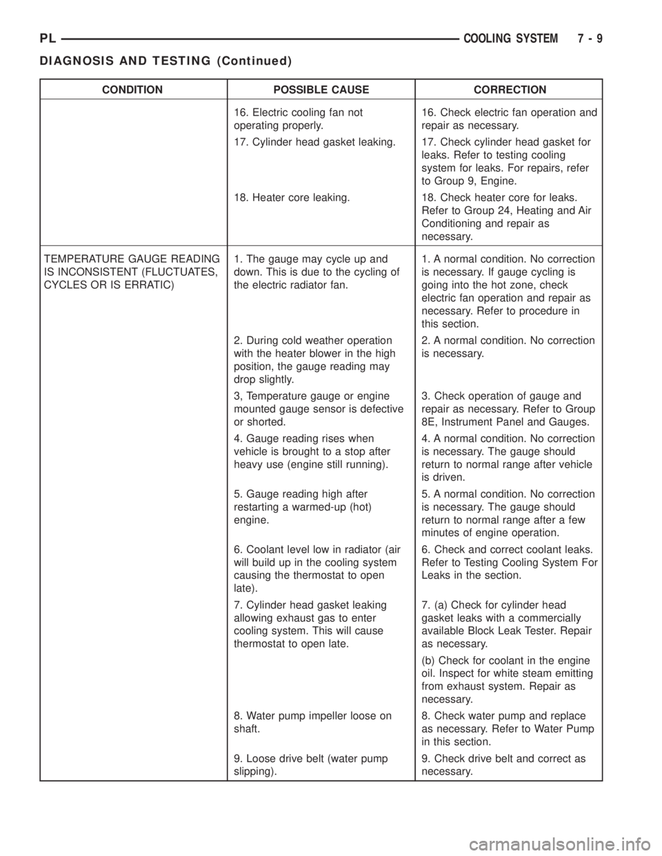
CONDITION POSSIBLE CAUSE CORRECTION
16. Electric cooling fan not
operating properly.16. Check electric fan operation and
repair as necessary.
17. Cylinder head gasket leaking. 17. Check cylinder head gasket for
leaks. Refer to testing cooling
system for leaks. For repairs, refer
to Group 9, Engine.
18. Heater core leaking. 18. Check heater core for leaks.
Refer to Group 24, Heating and Air
Conditioning and repair as
necessary.
TEMPERATURE GAUGE READING
IS INCONSISTENT (FLUCTUATES,
CYCLES OR IS ERRATIC)1. The gauge may cycle up and
down. This is due to the cycling of
the electric radiator fan.1. A normal condition. No correction
is necessary. If gauge cycling is
going into the hot zone, check
electric fan operation and repair as
necessary. Refer to procedure in
this section.
2. During cold weather operation
with the heater blower in the high
position, the gauge reading may
drop slightly.2. A normal condition. No correction
is necessary.
3, Temperature gauge or engine
mounted gauge sensor is defective
or shorted.3. Check operation of gauge and
repair as necessary. Refer to Group
8E, Instrument Panel and Gauges.
4. Gauge reading rises when
vehicle is brought to a stop after
heavy use (engine still running).4. A normal condition. No correction
is necessary. The gauge should
return to normal range after vehicle
is driven.
5. Gauge reading high after
restarting a warmed-up (hot)
engine.5. A normal condition. No correction
is necessary. The gauge should
return to normal range after a few
minutes of engine operation.
6. Coolant level low in radiator (air
will build up in the cooling system
causing the thermostat to open
late).6. Check and correct coolant leaks.
Refer to Testing Cooling System For
Leaks in the section.
7. Cylinder head gasket leaking
allowing exhaust gas to enter
cooling system. This will cause
thermostat to open late.7. (a) Check for cylinder head
gasket leaks with a commercially
available Block Leak Tester. Repair
as necessary.
(b) Check for coolant in the engine
oil. Inspect for white steam emitting
from exhaust system. Repair as
necessary.
8. Water pump impeller loose on
shaft.8. Check water pump and replace
as necessary. Refer to Water Pump
in this section.
9. Loose drive belt (water pump
slipping).9. Check drive belt and correct as
necessary.
PLCOOLING SYSTEM 7 - 9
DIAGNOSIS AND TESTING (Continued)