2000 DODGE NEON charging
[x] Cancel search: chargingPage 1 of 1285

GROUP TAB LOCATORINIntroductionINaIntroduction0Lubrication and Maintenance2Suspension3Differential and Driveline5Brakes6Clutch7Cooling8ABattery8BStarting8CCharging System8DIgnition System8EInstrument Panel and Systems8EaInstrument Panel and Systems8FAudio System8GHorns8HVehicle Speed Control System8JTurn Signal and Flashers8KWindshield Wipers and Washers8LLamps8LaLamps8MRestraint System8NElectrically Heated Systems8OPower Distribution Systems8PPower Door Locks8QImmobilizer System8SPower Windows8TPower Mirrors8TaPower Mirrors8UChime Warning/Reminder System8WWiring Diagrams - LHD and RHD9Engine11Exhaust System13Frame and Bumpers14Fuel System19Steering21Transaxle22Tires and Wheels23Body24Heating and Air Conditioning24aHeating and Air Conditioning25Emission Control Systems
Page 8 of 1285

JUMP STARTING, TOWING, AND HOISTING
TABLE OF CONTENTS
page page
DESCRIPTION AND OPERATION
JUMP STARTING PROCEDURE...............7
TOWING RECOMMENDATIONS...............7
HOISTING RECOMMENDATIONS.............7SERVICE PROCEDURES
JUMP STARTING PROCEDURE...............7
TOWING RECOMMENDATIONS...............8
HOISTING RECOMMENDATIONS.............9
DESCRIPTION AND OPERATION
JUMP STARTING PROCEDURE
Describes the procedure for starting a disable vehi-
cle.
TOWING RECOMMENDATIONS
Describes the recommended towing procedures.
HOISTING RECOMMENDATIONS
Describes the location of hoisting and jacking
points so that the vehicle can be lifted by a floor jack
or hoist.
SERVICE PROCEDURES
JUMP STARTING PROCEDURE
WARNING: REVIEW ALL SAFETY PRECAUTIONS
AND WARNINGS IN GROUP 8A, BATTERY/START-
ING/CHARGING SYSTEMS DIAGNOSTICS. DO NOT
JUMP START A FROZEN BATTERY, PERSONAL
INJURY CAN RESULT. DO NOT JUMP START WHEN
MAINTENANCE FREE BATTERY INDICATOR DOT IS
YELLOW OR BRIGHT COLOR. DO NOT JUMP
START A VEHICLE WHEN THE BATTERY FLUID IS
BELOW THE TOP OF LEAD PLATES. DO NOT
ALLOW JUMPER CABLE CLAMPS TO TOUCH
EACH OTHER WHEN CONNECTED TO A BOOSTER
SOURCE. DO NOT USE OPEN FLAME NEAR BAT-
TERY. REMOVE METALLIC JEWELRY WORN ON
HANDS OR WRISTS TO AVOID INJURY BY ACCI-
DENTAL ARCING OF BATTERY CURRENT. WHEN
USING A HIGH OUTPUT BOOSTING DEVICE, DO
NOT ALLOW BATTERY VOLTAGE TO EXCEED 16
VOLTS. REFER TO INSTRUCTIONS PROVIDED
WITH DEVICE BEING USED.
CAUTION: When using another vehicle as a
booster, do not allow vehicles to touch. Electrical
systems can be damaged on either vehicle.
TO JUMP START A DISABLED VEHICLE:
(1) Raise hood on disabled vehicle and visually
inspect engine compartment for:
²Battery cable clamp condition, clean if necessary.
²Frozen battery.
²Yellow or bright color test indicator, if equipped.
²Low battery fluid level.
²Generator drive belt condition and tension.
²Fuel fumes or leakage, correct if necessary.
CAUTION: If the cause of starting problem on dis-
abled vehicle is severe, damage to booster vehicle
charging system can result.
(2) When using another vehicle as a booster
source, park the booster vehicle within cable reach.
Turn off all accessories, set the parking brake, place
the automatic transmission in PARK or the manual
transmission in NEUTRAL and turn the ignition
OFF.
(3) On disabled vehicle, place gear selector in park
or neutral and set park brake. Turn off all accesso-
ries.
(4) Connect jumper cables to booster battery. RED
clamp to positive terminal (+). BLACK clamp to neg-
ative terminal (-). DO NOT allow clamps at opposite
end of cables to touch, electrical arc will result.
Review all warnings in this procedure.
(5) On disabled vehicle, connect RED jumper cable
clamp to positive (+) terminal. Connect BLACK
jumper cable clamp to engine ground as close to the
ground cable attaching point as possible (Fig. 1).
(6) Start the engine in the vehicle which has the
booster battery, let the engine idle a few minutes,
then start the engine in the vehicle with the dis-
charged battery.
CAUTION: Do not crank starter motor on disabled
vehicle for more than 15 seconds, starter will over-
heat and could fail.
(7) Allow battery in disabled vehicle to charge to
at least 12.4 volts (75% charge) before attempting to
start engine. If engine does not start within 15 sec-
PLLUBRICATION AND MAINTENANCE 0 - 7
Page 172 of 1285
SERVICE DIAGNOSIS±CLUTCH INTERLOCK/UPSTOP SWITCH
CONDITION POSSIBLE CAUSES CORRECTION
ENGINE STARTER
WON'T CRANK
WHEN CLUTCH
PEDAL IS
PRESSED TO THE
FLOORClutch interlock switch does not have
continuity when plunger is depressed 1.25
mm (1.30 in.)Defective switch or open wiring circuit.
Replace switch if necessary.
Interlock switch plunger is not depressed
when clutch pedal is pushed to the floorFloor mat interferes with clutch pedal
movement or clutch pedal bracket is bent.
Problem is related to other components in
the starting circuit.Check other components in the starting
circuit. Refer to Battery/Starting/Charging
System in Group 8.
SPEED CONTROL
DOES NOT
TERMINATE WHEN
CLUTCH PEDAL IS
DEPRESSED BY AT
LEAST 33 mm (1.30
in.)Upstop switch circuit is closed when clutch
pedal is depressed, or harness is shorted.Refer to Upstop Switch Electrical Test in
this group. Repair wiring or replace switch
assembly as necessary.
Other speed control system failure. Refer to Group 8H, Speed Control for
further diagnosis and testing procedures.
REMOVAL AND INSTALLATION
CLUTCH CABLE
REMOVAL
(1) Disconnect both battery cables.
(2) Remove battery clamp and remove battery
from vehicle.
(3) Remove battery tray from mount bracket.
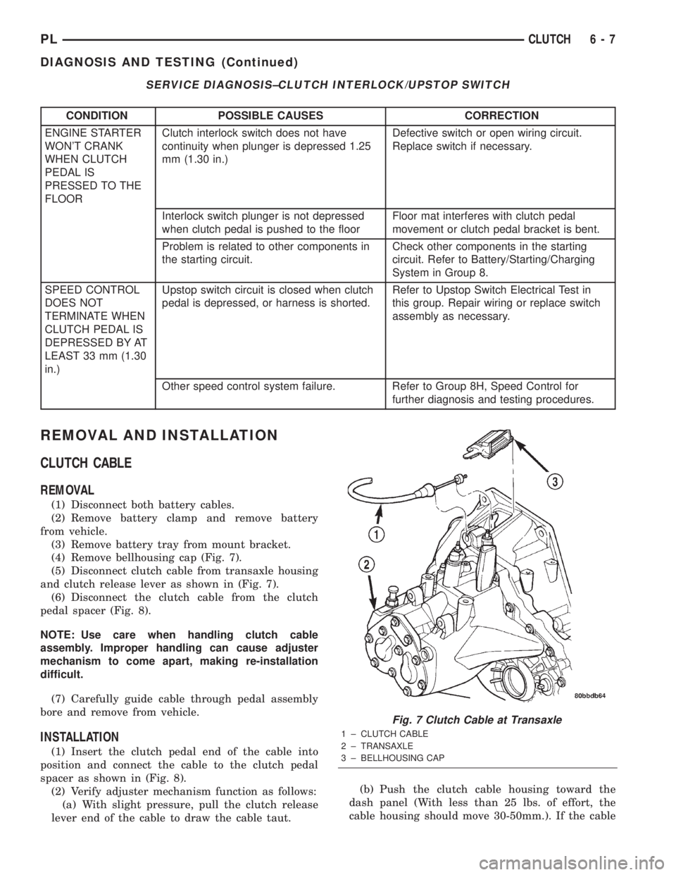
(4) Remove bellhousing cap (Fig. 7).
(5) Disconnect clutch cable from transaxle housing
and clutch release lever as shown in (Fig. 7).
(6) Disconnect the clutch cable from the clutch
pedal spacer (Fig. 8).
NOTE: Use care when handling clutch cable
assembly. Improper handling can cause adjuster
mechanism to come apart, making re-installation
difficult.
(7) Carefully guide cable through pedal assembly
bore and remove from vehicle.
INSTALLATION
(1) Insert the clutch pedal end of the cable into
position and connect the cable to the clutch pedal
spacer as shown in (Fig. 8).
(2) Verify adjuster mechanism function as follows:
(a) With slight pressure, pull the clutch release
lever end of the cable to draw the cable taut.(b) Push the clutch cable housing toward the
dash panel (With less than 25 lbs. of effort, the
cable housing should move 30-50mm.). If the cable
Fig. 7 Clutch Cable at Transaxle
1 ± CLUTCH CABLE
2 ± TRANSAXLE
3 ± BELLHOUSING CAP
PLCLUTCH 6 - 7
DIAGNOSIS AND TESTING (Continued)
Page 184 of 1285
RADIATOR HOSES AND CLAMPS
WARNING: IF VEHICLE HAS BEEN RUN RECENTLY,
WAIT 15 MINUTES BEFORE WORKING ON VEHI-
CLE. RELIEVE PRESSURE BY PLACING A SHOP
TOWEL OVER THE CAP AND WITHOUT PUSHING
DOWN ROTATE IT COUNTERCLOCKWISE TO THE
FIRST STOP. ALLOW FLUIDS TO ESCAPE
THROUGH THE OVERFLOW TUBE AND WHEN THE
SYSTEM STOPS PUSHING OUT COOLANT AND
STEAM AND THE PRESSURE DROPS CONTINUE
SERVICE.
WARNING: CONSTANT TENSION HOSE CLAMPS
ARE USED ON MOST COOLING SYSTEM HOSES.
WHEN REMOVING OR INSTALLING, USE ONLY
TOOLS DESIGNED FOR SERVICING THIS TYPE OF
CLAMP. ALWAYS WEAR SAFETY GLASSES WHEN
SERVICING CONSTANT TENSION CLAMPS.
CAUTION: A number or letter is stamped into the
tongue of constant tension clamps. If replacement
is necessary, use only a original equipment clamp
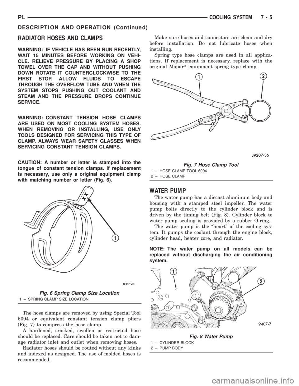
with matching number or letter (Fig. 6).
The hose clamps are removed by using Special Tool
6094 or equivalent constant tension clamp pliers
(Fig. 7) to compress the hose clamp.
A hardened, cracked, swollen or restricted hose
should be replaced. Care should be taken not to dam-
age radiator inlet and outlet when removing hoses.
Radiator hoses should be routed without any kinks
and indexed as designed. The use of molded hoses is
recommended.Make sure hoses and connectors are clean and dry
before installation. Do not lubricate hoses when
installing.
Spring type hose clamps are used in all applica-
tions. If replacement is necessary, replace with the
original Mopartequipment spring type clamp.
WATER PUMP
The water pump has a diecast aluminum body and
housing with a stamped steel impeller. The water
pump bolts directly to the cylinder block and is
driven by the timing belt (Fig. 8). Cylinder block to
water pump sealing is provided by a rubber O-ring.
The water pump is the ªheartº of the cooling sys-
tem. It pumps the coolant through the engine block,
cylinder head, heater core, and radiator.
NOTE: The water pump on all models can be
replaced without discharging the air conditioning
system.
Fig. 6 Spring Clamp Size Location
1 ± SPRING CLAMP SIZE LOCATION
Fig. 7 Hose Clamp Tool
1 ± HOSE CLAMP TOOL 6094
2 ± HOSE CLAMP
Fig. 8 Water Pump
1 ± CYLINDER BLOCK
2 ± PUMP BODY
PLCOOLING SYSTEM 7 - 5
DESCRIPTION AND OPERATION (Continued)
Page 210 of 1285
BATTERY
TABLE OF CONTENTS
page page
GENERAL INFORMATION
INTRODUCTION..........................1
DESCRIPTION AND OPERATION
BATTERY IGNITION OFF DRAW (IOD).........2
CHARGING TIME REQUIRED................2
DIAGNOSIS AND TESTING
BATTERY BUILT-IN TEST INDICATOR.........3
BATTERY IGNITION OFF DRAW (IOD).........4
BATTERY LOAD TEST......................6
BATTERY OPEN CIRCUIT VOLTAGE...........7
SERVICE PROCEDURES
BATTERY CHARGING......................7CHARGING COMPLETELY DISCHARGED
BATTERY..............................8
VISUAL INSPECTION......................9
REMOVAL AND INSTALLATION
BATTERY...............................10
BATTERY THERMOWRAP..................10
BATTERY TRAY..........................11
SPECIFICATIONS
BATTERY SPECIFICATIONS................11
TORQUE...............................11
GENERAL INFORMATION
INTRODUCTION
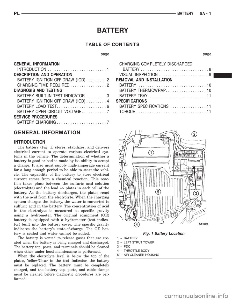
The battery (Fig. 1) stores, stabilizes, and delivers
electrical current to operate various electrical sys-
tems in the vehicle. The determination of whether a
battery is good or bad is made by its ability to accept
a charge. It also must supply high-amperage current
for a long enough period to be able to start the vehi-
cle. The capability of the battery to store electrical
current comes from a chemical reaction. This reac-
tion takes place between the sulfuric acid solution
(electrolyte) and the lead +/- plates in each cell of the
battery. As the battery discharges, the plates react
with the acid from the electrolyte. When the charging
system charges the battery, the water is converted to
sulfuric acid in the battery. The concentration of acid
in the electrolyte is measured as specific gravity
using a hydrometer. The original equipment (OE)
battery is equipped with a hydrometer (test indica-
tor) built into the battery cover. The specific gravity
indicates the battery's state-of-charge. The OE bat-
tery is sealed and water cannot be added.
The battery is vented to release gases that are cre-
ated when the battery is being charged and discharged.
The battery top, posts, and terminals should be cleaned
when other under hood maintenance is performed.
When the electrolyte level is below the top of the
plates, Yellow/Clear in the test Indicator, the battery
must be replaced. The battery must be completely
charged, and the battery top, posts, and cable clamps
must be cleaned before diagnostic procedures are per-
formed.
Fig. 1 Battery Location
1 ± BATTERY
2 ± LEFT STRUT TOWER
3 ± PDC
4 ± THROTTLE BODY
5 ± AIR CLEANER HOUSING
PLBATTERY 8A - 1
Page 211 of 1285
DESCRIPTION AND OPERATION
BATTERY IGNITION OFF DRAW (IOD)
A completely normal vehicle will have a small
amount of current drain on the battery with the key
out of the ignition. It can range from 4 to 10 milli-
amperes after all the modules time out. If a vehicle
will not be operated for approximately a 20 days, the
IOD fuse should be disconnected to minimize the
vehicle electrical drain on the battery. The IOD fuse
is located in the Power Distribution Center (PDC).
Refer to the PDC cover to locate the proper fuse.
CHARGING TIME REQUIRED
WARNING: NEVER EXCEED 20 AMPS WHEN
CHARGING A COLD -1ÉC (30ÉF) BATTERY. PER-
SONAL INJURY MAY RESULT.
The time required to charge a battery will vary
depending upon the following factors.
SIZE OF BATTERY
A completely discharged large heavy-duty battery
may require more recharging time than a completely
discharged small capacity battery, refer to Battery
Charging Timetable for charging times.
TEMPERATURE
A longer time will be needed to charge a battery at
-18ÉC (0ÉF) than at 27ÉC (80ÉF). When a fast charger
is connected to a cold battery, current accepted by
battery will be very low at first. In time, the battery
will accept a higher rate as battery temperature
warms.
CHARGER CAPACITY
A charger which can supply only five amperes will
require a much longer period of charging than a
charger that can supply 20 amperes or more.
STATE OF CHARGE
A completely discharged battery requires more
charging time than a partially charged battery.
NOTE: Do not attempt to recharge a battery with a
yellow/clear test indicator.
Electrolyte is nearly pure water in a completely
discharged battery. At first, the charging current
amperage will be low. As water is converted back to
sulfuric acid inside the battery, the current amp rate
will rise. Also, the specific gravity of the electrolyte
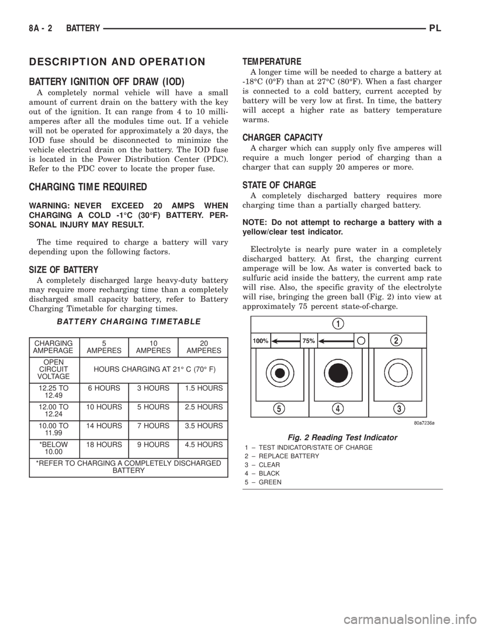
will rise, bringing the green ball (Fig. 2) into view at
approximately 75 percent state-of-charge.
BATTERY CHARGING TIMETABLE
CHARGING
AMPERAGE5
AMPERES10
AMPERES20
AMPERES
OPEN
CIRCUIT
VOLTAGEHOURS CHARGING AT 21É C (70É F)
12.25 TO
12.496 HOURS 3 HOURS 1.5 HOURS
12.00 TO
12.2410 HOURS 5 HOURS 2.5 HOURS
10.00 TO
11.9914 HOURS 7 HOURS 3.5 HOURS
*BELOW
10.0018 HOURS 9 HOURS 4.5 HOURS
*REFER TO CHARGING A COMPLETELY DISCHARGED
BATTERY
Fig. 2 Reading Test Indicator
1 ± TEST INDICATOR/STATE OF CHARGE
2 ± REPLACE BATTERY
3 ± CLEAR
4 ± BLACK
5 ± GREEN
8A - 2 BATTERYPL
Page 212 of 1285
DIAGNOSIS AND TESTING
BATTERY BUILT-IN TEST INDICATOR
USING TEST INDICATOR
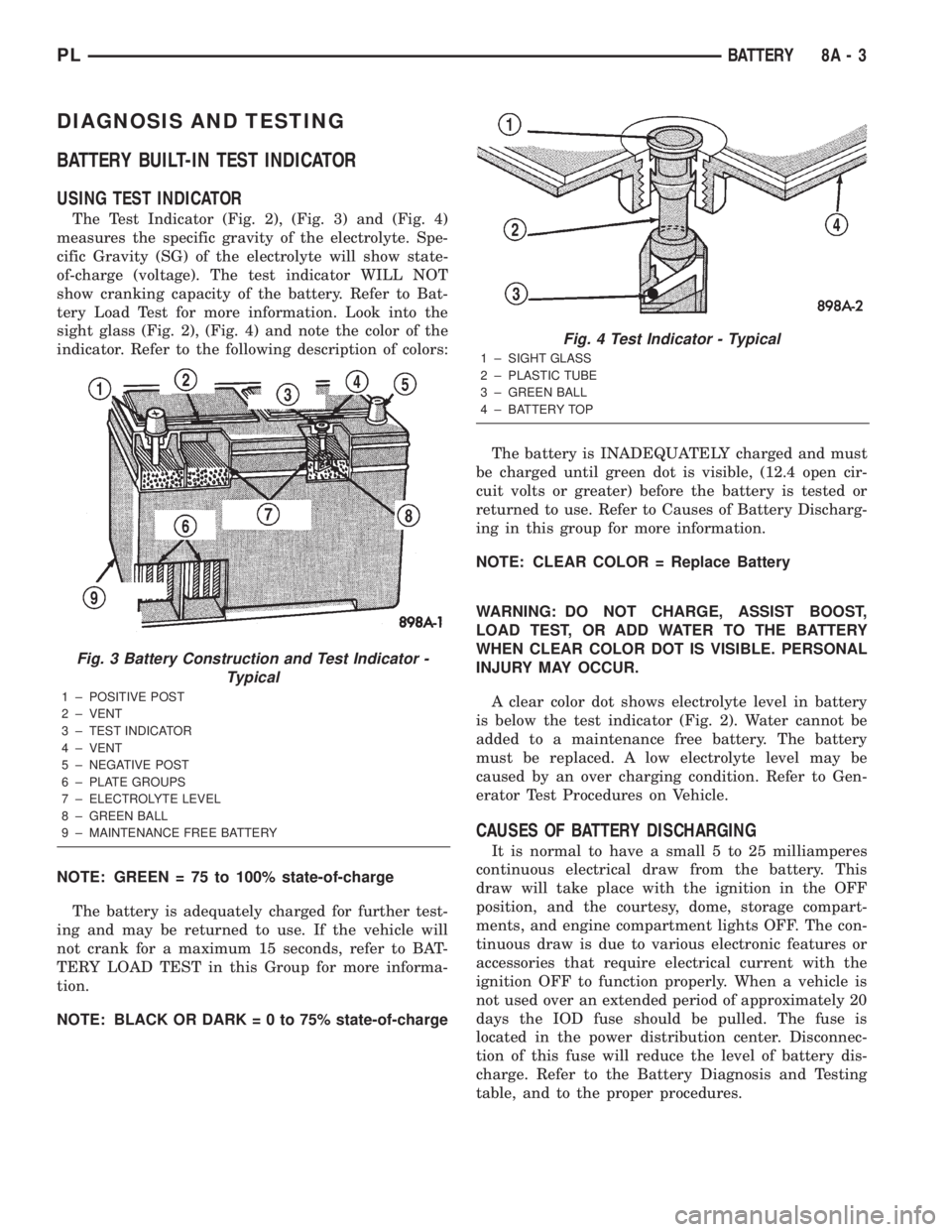
The Test Indicator (Fig. 2), (Fig. 3) and (Fig. 4)
measures the specific gravity of the electrolyte. Spe-
cific Gravity (SG) of the electrolyte will show state-
of-charge (voltage). The test indicator WILL NOT
show cranking capacity of the battery. Refer to Bat-
tery Load Test for more information. Look into the
sight glass (Fig. 2), (Fig. 4) and note the color of the
indicator. Refer to the following description of colors:
NOTE: GREEN = 75 to 100% state-of-charge
The battery is adequately charged for further test-
ing and may be returned to use. If the vehicle will
not crank for a maximum 15 seconds, refer to BAT-
TERY LOAD TEST in this Group for more informa-
tion.
NOTE: BLACK OR DARK=0to75%state-of-chargeThe battery is INADEQUATELY charged and must
be charged until green dot is visible, (12.4 open cir-
cuit volts or greater) before the battery is tested or
returned to use. Refer to Causes of Battery Discharg-
ing in this group for more information.
NOTE: CLEAR COLOR = Replace Battery
WARNING: DO NOT CHARGE, ASSIST BOOST,
LOAD TEST, OR ADD WATER TO THE BATTERY
WHEN CLEAR COLOR DOT IS VISIBLE. PERSONAL
INJURY MAY OCCUR.
A clear color dot shows electrolyte level in battery
is below the test indicator (Fig. 2). Water cannot be
added to a maintenance free battery. The battery
must be replaced. A low electrolyte level may be
caused by an over charging condition. Refer to Gen-
erator Test Procedures on Vehicle.
CAUSES OF BATTERY DISCHARGING
It is normal to have a small 5 to 25 milliamperes
continuous electrical draw from the battery. This
draw will take place with the ignition in the OFF
position, and the courtesy, dome, storage compart-
ments, and engine compartment lights OFF. The con-
tinuous draw is due to various electronic features or
accessories that require electrical current with the
ignition OFF to function properly. When a vehicle is
not used over an extended period of approximately 20
days the IOD fuse should be pulled. The fuse is
located in the power distribution center. Disconnec-
tion of this fuse will reduce the level of battery dis-
charge. Refer to the Battery Diagnosis and Testing
table, and to the proper procedures.
Fig. 3 Battery Construction and Test Indicator -
Typical
1 ± POSITIVE POST
2 ± VENT
3 ± TEST INDICATOR
4 ± VENT
5 ± NEGATIVE POST
6 ± PLATE GROUPS
7 ± ELECTROLYTE LEVEL
8 ± GREEN BALL
9 ± MAINTENANCE FREE BATTERY
Fig. 4 Test Indicator - Typical
1 ± SIGHT GLASS
2 ± PLASTIC TUBE
3 ± GREEN BALL
4 ± BATTERY TOP
PLBATTERY 8A - 3
Page 213 of 1285
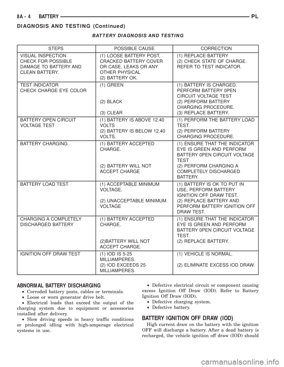
BATTERY DIAGNOSIS AND TESTING
STEPS POSSIBLE CAUSE CORRECTION
VISUAL INSPECTION
CHECK FOR POSSIBLE
DAMAGE TO BATTERY AND
CLEAN BATTERY.(1) LOOSE BATTERY POST,
CRACKED BATTERY COVER
OR CASE, LEAKS OR ANY
OTHER PHYSICAL
(2) BATTERY OK.(1) REPLACE BATTERY
(2) CHECK STATE OF CHARGE.
REFER TO TEST INDICATOR.
TEST INDICATOR
CHECK CHARGE EYE COLOR(1) GREEN
(2) BLACK
(3) CLEAR(1) BATTERY IS CHARGED.
PERFORM BATTERY 0PEN
CIRCUIT VOLTAGE TEST
(2) PERFORM BATTERY
CHARGING PROCEDURE.
(3) REPLACE BATTERY.
BATTERY OPEN CIRCUIT
VOLTAGE TEST(1) BATTERY IS ABOVE 12.40
VOLTS
(2) BATTERY IS BELOW 12.40
VOLTS.(1) PERFORM THE BATTERY LOAD
TEST.
(2) PERFORM BATTERY
CHARGING PROCEDURE.
BATTERY CHARGING (1) BATTERY ACCEPTED
CHARGE.
(2) BATTERY WILL NOT
ACCEPT CHARGE(1) ENSURE THAT THE INDICATOR
EYE IS GREEN AND PERFORM
BATTERY 0PEN CIRCUIT VOLTAGE
TEST
(2) PERFORM CHARGING A
COMPLETELY DISCHARGED
BATTERY.
BATTERY LOAD TEST (1) ACCEPTABLE MINIMUM
VOLTAGE.
(2) UNACCEPTABLE MINIMUM
VOLTAGE(1) BATTERY IS OK TO PUT IN
USE, PERFORM BATTERY
IGNITION OFF DRAW TEST.
(2) REPLACE BATTERY AND
PERFORM BATTERY IGNITION OFF
DRAW TEST.
CHARGING A COMPLETELY
DISCHARGED BATTERY(1) BATTERY ACCEPTED
CHARGE.
(2)BATTERY WILL NOT
ACCEPT CHARGE.(1) ENSURE THAT THE INDICATOR
EYE IS GREEN AND PERFORM
BATTERY 0PEN CIRCUIT VOLTAGE
TEST.
(2) REPLACE BATTERY.
IGNITION OFF DRAW TEST (1) IOD IS 5-25
MILLIAMPERES.
(2) IOD EXCEEDS 25
MILLIAMPERES.(1) VEHICLE IS NORMAL.
(2) ELIMINATE EXCESS IOD DRAW.
ABNORMAL BATTERY DISCHARGING
²Corroded battery posts, cables or terminals.
²Loose or worn generator drive belt.
²Electrical loads that exceed the output of the
charging system due to equipment or accessories
installed after delivery.
²Slow driving speeds in heavy traffic conditions
or prolonged idling with high-amperage electrical
systems in use.²Defective electrical circuit or component causing
excess Ignition Off Draw (IOD). Refer to Battery
Ignition Off Draw (IOD).
²Defective charging system.
²Defective battery.
BATTERY IGNITION OFF DRAW (IOD)
High current draw on the battery with the ignition
OFF will discharge a battery. After a dead battery is
recharged, the vehicle ignition off draw (IOD) should
8A - 4 BATTERYPL
DIAGNOSIS AND TESTING (Continued)