2000 DODGE NEON charging
[x] Cancel search: chargingPage 215 of 1285
Refer to Group 8W, Wiring Diagrams. If OK go to
Step 7.
(7) Install interior lamp fuse. After installing fuse,
the current can reach 250 milliamperes. After time-
out the reading should not exceed 8 milliamperes. If
NOT OK go to Step 8. If OK go to Step 9.
²Ignition key lamp system
²Radio
²Remote keyless entry module, if equipped
(8) Disconnect radio and ignition switch key lamp
one component at time, to see if any component is at
fault. If the high reading is not eliminated there is a
short circuit in the wiring. Refer to Group 8W, Wir-
ing Diagrams.
CAUTION: Always disconnect the meter before
opening a door.
(9) Remove interior lamps fuse and install the fuel
pump fuse. The reading should be between 1-3 milli-
amperes. If reading is higher than 3 milliamperes:
(a) Disconnect Powertrain Control Module.
(b) If reading drops to zero, replace Powertrain
Control Module.
(c) If reading remains the same there is a cur-
rent draw or short circuit in the A14 circuit. Refer
to Group 8W, Wiring Diagrams.
BATTERY LOAD TEST
A fully charged battery must have cranking capac-
ity, to provide the starter motor and ignition system
enough power to start the engine over a broad range
of ambient temperatures. A battery load test will ver-
ify the actual cranking capability of the battery.WARNING: IF BATTERY SHOWS SIGNS OF FREEZ-
ING, LEAKING, LOOSE POSTS, OR EXCESSIVELY
LOW ELECTROLYTE LEVEL, DO NOT TEST. ACID
BURNS OR AN EXPLOSIVE CONDITION MAY
RESULT.
(1) Remove both battery cables, negative cable
first. The battery top, cables and posts should be
clean. If green dot is not visible in indicator, charge
the battery. Refer to Battery Charging Procedures in
this group.
(2) Connect a Volt/Ammeter/Load tester to the bat-
tery posts (Fig. 8). Rotate the load control knob of the
Carbon pile rheostat to apply a 300 amp load. Apply
this load for 15 seconds to remove the surface charge
from the battery, and return the control knob to off
(Fig. 9).
(3) Allow the battery to stabilize for 2 minutes,
and then verify open circuit voltage.
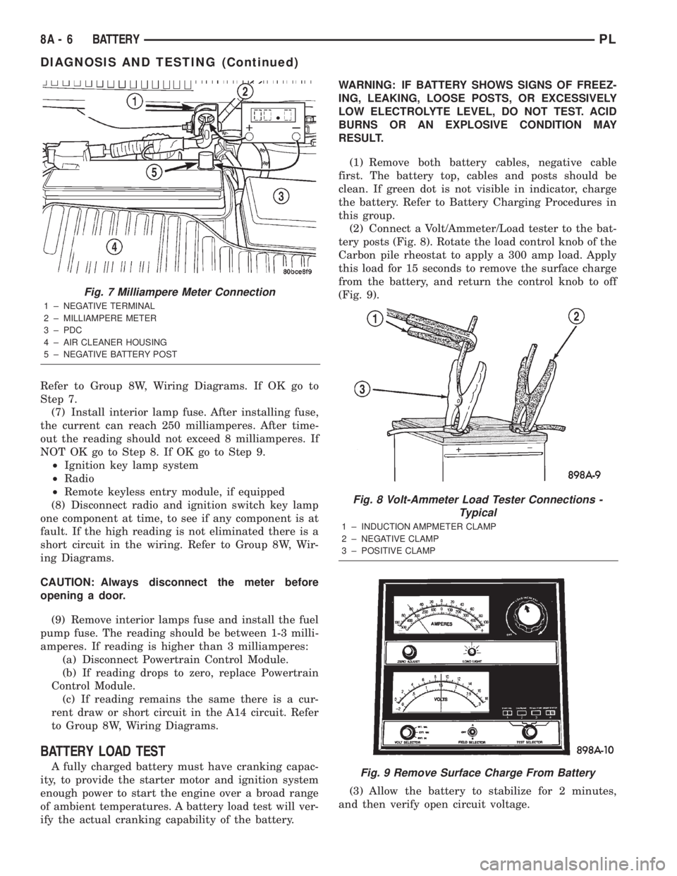
Fig. 7 Milliampere Meter Connection
1 ± NEGATIVE TERMINAL
2 ± MILLIAMPERE METER
3 ± PDC
4 ± AIR CLEANER HOUSING
5 ± NEGATIVE BATTERY POST
Fig. 8 Volt-Ammeter Load Tester Connections -
Typical
1 ± INDUCTION AMPMETER CLAMP
2 ± NEGATIVE CLAMP
3 ± POSITIVE CLAMP
Fig. 9 Remove Surface Charge From Battery
8A - 6 BATTERYPL
DIAGNOSIS AND TESTING (Continued)
Page 216 of 1285
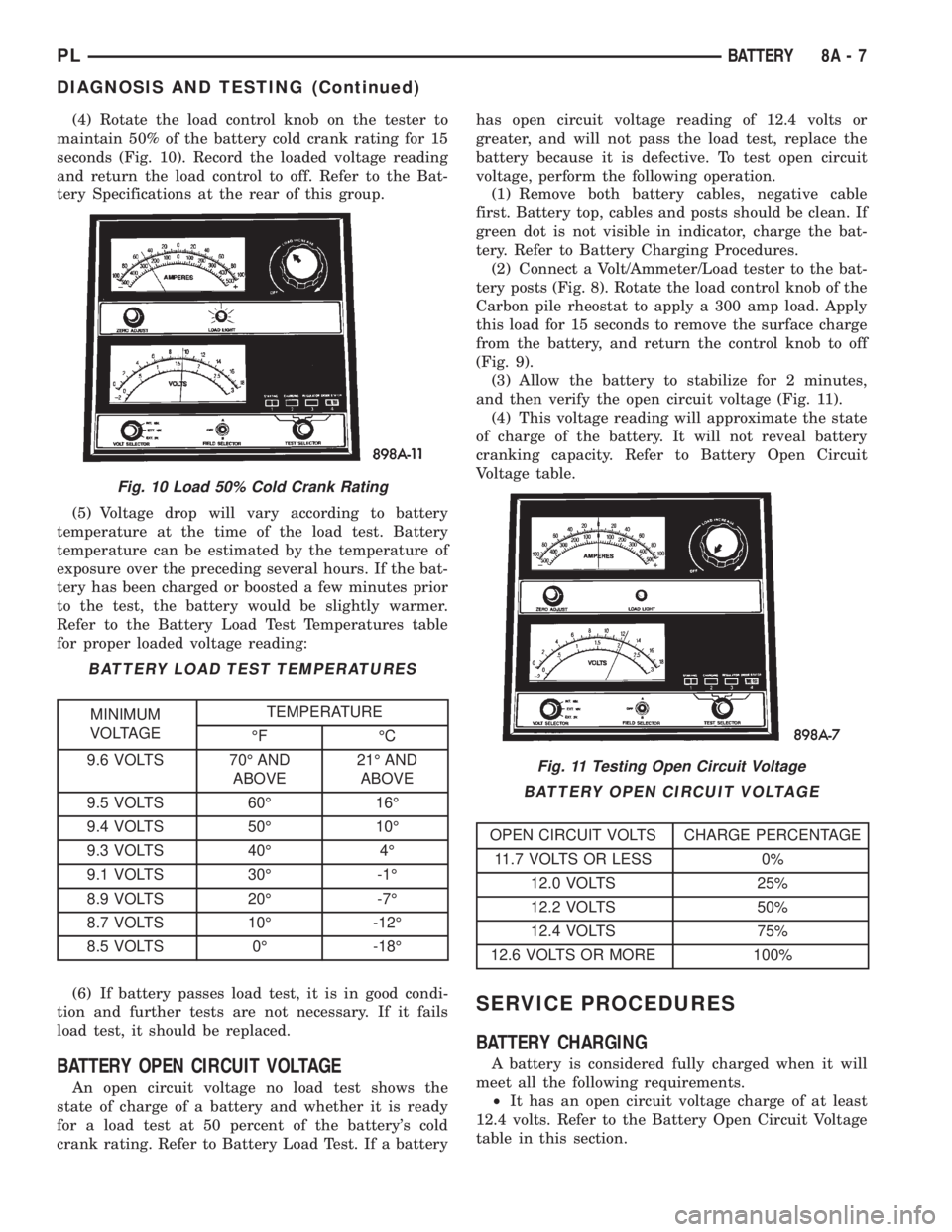
(4) Rotate the load control knob on the tester to
maintain 50% of the battery cold crank rating for 15
seconds (Fig. 10). Record the loaded voltage reading
and return the load control to off. Refer to the Bat-
tery Specifications at the rear of this group.
(5) Voltage drop will vary according to battery
temperature at the time of the load test. Battery
temperature can be estimated by the temperature of
exposure over the preceding several hours. If the bat-
tery has been charged or boosted a few minutes prior
to the test, the battery would be slightly warmer.
Refer to the Battery Load Test Temperatures table
for proper loaded voltage reading:
(6) If battery passes load test, it is in good condi-
tion and further tests are not necessary. If it fails
load test, it should be replaced.
BATTERY OPEN CIRCUIT VOLTAGE
An open circuit voltage no load test shows the
state of charge of a battery and whether it is ready
for a load test at 50 percent of the battery's cold
crank rating. Refer to Battery Load Test. If a batteryhas open circuit voltage reading of 12.4 volts or
greater, and will not pass the load test, replace the
battery because it is defective. To test open circuit
voltage, perform the following operation.
(1) Remove both battery cables, negative cable
first. Battery top, cables and posts should be clean. If
green dot is not visible in indicator, charge the bat-
tery. Refer to Battery Charging Procedures.
(2) Connect a Volt/Ammeter/Load tester to the bat-
tery posts (Fig. 8). Rotate the load control knob of the
Carbon pile rheostat to apply a 300 amp load. Apply
this load for 15 seconds to remove the surface charge
from the battery, and return the control knob to off
(Fig. 9).
(3) Allow the battery to stabilize for 2 minutes,
and then verify the open circuit voltage (Fig. 11).
(4) This voltage reading will approximate the state
of charge of the battery. It will not reveal battery
cranking capacity. Refer to Battery Open Circuit
Voltage table.
SERVICE PROCEDURES
BATTERY CHARGING
A battery is considered fully charged when it will
meet all the following requirements.
²It has an open circuit voltage charge of at least
12.4 volts. Refer to the Battery Open Circuit Voltage
table in this section.
Fig. 10 Load 50% Cold Crank Rating
BATTERY LOAD TEST TEMPERATURES
MINIMUM
VOLTAGETEMPERATURE
ÉF ÉC
9.6 VOLTS 70É AND
ABOVE21É AND
ABOVE
9.5 VOLTS 60É 16É
9.4 VOLTS 50É 10É
9.3 VOLTS 40É 4É
9.1 VOLTS 30É -1É
8.9 VOLTS 20É -7É
8.7 VOLTS 10É -12É
8.5 VOLTS 0É -18É
Fig. 11 Testing Open Circuit Voltage
BATTERY OPEN CIRCUIT VOLTAGE
OPEN CIRCUIT VOLTS CHARGE PERCENTAGE
11.7 VOLTS OR LESS 0%
12.0 VOLTS 25%
12.2 VOLTS 50%
12.4 VOLTS 75%
12.6 VOLTS OR MORE 100%
PLBATTERY 8A - 7
DIAGNOSIS AND TESTING (Continued)
Page 217 of 1285
²It passes the 15 second load test. Refer to Bat-
tery Load Test.
²The built in test indicator dot is GREEN (Fig.
2).
NOTE: The battery cannot be refilled with water, it
must be replaced.
WARNING: DO NOT CHARGE A BATTERY THAT
HAS EXCESSIVELY LOW ELECTROLYTE LEVEL.
BATTERY MAY SPARK INTERNALLY AND
EXPLODE. EXPLOSIVE GASES FORM OVER THE
BATTERY. DO NOT SMOKE, USE FLAME, OR CRE-
ATE SPARKS NEAR BATTERY. DO NOT ASSIST
BOOST OR CHARGE A FROZEN BATTERY. BAT-
TERY CASING MAY FRACTURE. BATTERY ACID IS
POISON, AND MAY CAUSE SEVERE BURNS. BAT-
TERIES CONTAIN SULFURIC ACID. AVOID CON-
TACT WITH SKIN, EYES, OR CLOTHING. IN THE
EVENT OF CONTACT, FLUSH WITH WATER AND
CALL PHYSICIAN IMMEDIATELY. KEEP OUT OF
REACH OF CHILDREN.
CAUTION: Disconnect the battery NEGATIVE cable
first, before charging battery to avoid damage to
electrical systems. Lift the red battery boot cover
from the positive cable clamp. Do not exceed 16.0
volts while charging battery. Refer to the instruc-
tions supplied with charging equipment
Battery electrolyte may bubble inside of battery
case while being charged properly. If the electrolyte
boils violently, or is discharged from the vent holes
while charging, immediately reduce charging rate or
turn off charger. Evaluate battery condition. Battery
damage may occur if charging is excessive.
Some battery chargers are equipped with polarity
sensing devices to protect the charger or battery from
being damaged if improperly connected. If the bat-
tery state of charge is too low for the polarity sensor
to detect, the sensor must be bypassed for charger to
operate. Refer to operating instructions provided
with battery charger being used.
CAUTION: Charge battery until test indicator
appears green. Do not overcharge.
It may be necessary to jiggle the battery or vehicle
to bring the green dot in the test indicator into view.
After the battery has been charged to 12.4 volts or
greater, perform a load test to determine cranking
capacity. Refer to Battery Load Test in this Group. If
the battery passes the load test, the battery is OK to
use. If battery will not pass the load test, it must be
replaced. Properly clean and inspect battery holddowns, tray, terminals, cables, posts, and top before
completing service.
CHARGING COMPLETELY DISCHARGED
BATTERY
The following procedure should be used to recharge
a completely discharged battery. Unless procedure is
properly followed, a good battery may be needlessly
replaced. Refer to Battery Charging Rate Table for
proper charging time.
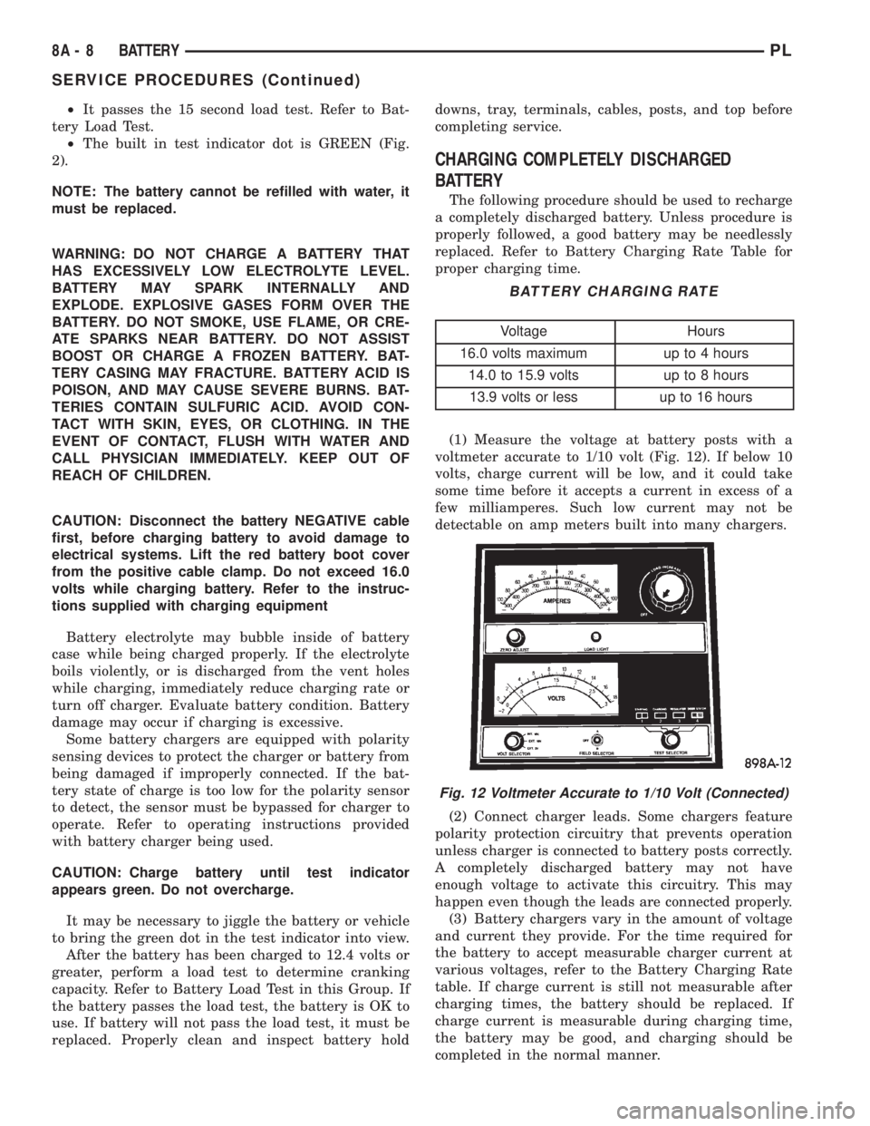
(1) Measure the voltage at battery posts with a
voltmeter accurate to 1/10 volt (Fig. 12). If below 10
volts, charge current will be low, and it could take
some time before it accepts a current in excess of a
few milliamperes. Such low current may not be
detectable on amp meters built into many chargers.
(2) Connect charger leads. Some chargers feature
polarity protection circuitry that prevents operation
unless charger is connected to battery posts correctly.
A completely discharged battery may not have
enough voltage to activate this circuitry. This may
happen even though the leads are connected properly.
(3) Battery chargers vary in the amount of voltage
and current they provide. For the time required for
the battery to accept measurable charger current at
various voltages, refer to the Battery Charging Rate
table. If charge current is still not measurable after
charging times, the battery should be replaced. If
charge current is measurable during charging time,
the battery may be good, and charging should be
completed in the normal manner.
BATTERY CHARGING RATE
Voltage Hours
16.0 volts maximum up to 4 hours
14.0 to 15.9 volts up to 8 hours
13.9 volts or less up to 16 hours
Fig. 12 Voltmeter Accurate to 1/10 Volt (Connected)
8A - 8 BATTERYPL
SERVICE PROCEDURES (Continued)
Page 229 of 1285
REMOVAL AND INSTALLATION
SAFETY SWITCHES
For Removal and Installation of:
²Clutch Interlock/Upstop Switch, refer to
Removal and Installation in Group 6-Clutch.
²Park/Neutral Starting and Back-Up Lamp
Switch, refer to Removal and Installation in Group
21-Transaxle.
STARTER MOTOR
REMOVAL
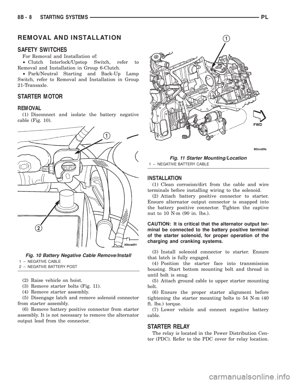
(1) Disconnect and isolate the battery negative
cable (Fig. 10).
(2) Raise vehicle on hoist.
(3) Remove starter bolts (Fig. 11).
(4) Remove starter assembly.
(5) Disengage latch and remove solenoid connector
from starter assembly.
(6) Remove battery positive connector from starter
assembly. It is not necessary to remove the alternator
output lead from the connector.
INSTALLATION
(1) Clean corrosion/dirt from the cable and wire
terminals before installing wiring to the solenoid.
(2) Attach battery positive connector to starter.
Ensure alternator output connector is snapped into
the battery positive connector. Tighten the captive
nut to 10 N´m (90 in. lbs.).
CAUTION: It is critical that the alternator output ter-
minal be connected to the battery positive terminal
of the starter solenoid, for proper operation of the
charging and cranking systems.
(3) Install solenoid connector to starter. Ensure
that latch is fully engaged.
(4) Position the starter face into transmission
housing. Start bottom mounting bolt and thread in
until bolt is snug.
(5) Attach ground cable to upper starter mounting
bolt.
(6) Ensure the proper starter alignment before
tightening the starter mounting bolts to 54 N´m (40
ft. lbs.) torque.
(7) Lower vehicle and connect negative battery
cable.
STARTER RELAY
The relay is located in the Power Distribution Cen-
ter (PDC). Refer to the PDC cover for relay location.
Fig. 10 Battery Negative Cable Remove/Install
1 ± NEGATIVE CABLE
2 ± NEGATIVE BATTERY POST
Fig. 11 Starter Mounting/Location
1 ± NEGATIVE BATTERY CABLE
8B - 8 STARTING SYSTEMSPL
Page 232 of 1285
CHARGING SYSTEM
TABLE OF CONTENTS
page page
DESCRIPTION AND OPERATION
CHARGING SYSTEM.......................1
GENERATOR.............................1
ELECTRONIC VOLTAGE REGULATOR..........1
REMOVAL AND INSTALLATION
GENERATOR.............................2SPECIFICATIONS
GENERATOR RATINGS.....................3
TORQUE................................3
DESCRIPTION AND OPERATION
CHARGING SYSTEM
DESCRIPTION
The charging system consists of:
²Generator
²Electronic Voltage Regulator (EVR) circuitry
within the Powertrain Control Module (PCM)
²Ignition switch (refer to the Ignition System for
information)
²Battery (refer to the Battery for information)
²Battery temperature sensor
²Wiring harness and connections (refer to the
Wiring for information)
OPERATION
The charging system is turned on and off with the
ignition switch. When the ignition switch is turned to
the ON position, battery voltage is applied to the
generator rotor through one of the two field termi-
nals to produce a magnetic field. The generator is
driven by the engine through a serpentine belt and
pulley arrangement.
The amount of DC current produced by the gener-
ator is controlled by the EVR (field control) circuitry,
contained within the PCM. This circuitry is con-
nected in series with the second rotor field terminal
and ground.
Temperature data, along with data from monitored
line voltage, is used by the PCM to vary the battery
charging rate. This is done by cycling the ground
path to control the strength of the rotor magnetic
field. The PCM then compensates and regulates gen-
erator current output accordingly and to maintain
the proper voltage depending on battery tempera-
ture.
All vehicles are equipped with On-Board Diagnos-
tics (OBD). All OBD-sensed systems, including the
EVR (field control) circuitry, are monitored by thePCM. Each monitored circuit is assigned a Diagnos-
tic Trouble Code (DTC). The PCM will store a DTC in
electronic memory for any failure it detects.
GENERATOR
DESCRIPTION
The generator is belt-driven by the engine. It is
serviced only as a complete assembly. If the genera-
tor fails for any reason, the entire assembly must be
replaced.
OPERATION
As the energized rotor begins to rotate within the
generator, the spinning magnetic field induces a cur-
rent into the windings of the stator coil. Once the
generator begins producing sufficient current, it also
provides the current needed to energize the rotor.
The Y type stator winding connections deliver the
induced AC current to 3 positive and 3 negative
diodes for rectification. From the diodes, rectified DC
current is delivered to the vehicles electrical system
through the generator, battery, and ground terminals.
Noise emitting from the generator may be caused
by:
²Worn, loose or defective bearings
²Loose or defective drive pulley
²Incorrect, worn, damaged or misadjusted drive
belt
²Loose mounting bolts
²Misaligned drive pulley
²Defective stator or diode
²Damaged internal fins
ELECTRONIC VOLTAGE REGULATOR
DESCRIPTION
The Electronic Voltage Regulator (EVR) is not a
separate component. It is actually a voltage regulat-
ing circuit located within the Powertrain Control
PLCHARGING SYSTEM 8C - 1
Page 233 of 1285
Module (PCM). The EVR is not serviced separately. If
replacement is necessary, the PCM must be replaced.
OPERATION
The amount of DC current produced by the gener-
ator is controlled by EVR circuitry contained within
the PCM. This circuitry is connected in series with
the generators second rotor field terminal and its
ground.
Voltage is regulated by cycling the ground path to
control the strength of the rotor magnetic field. The
EVR circuitry monitors system line voltage (B+) and
battery temperature (refer to Battery Temperature
Sensor for more information). It then determines a
target charging voltage. If sensed battery voltage is
0.5 volts or lower than the target voltage, the PCM
grounds the field winding until sensed battery volage
is 0.5 volts above target voltage. A circuit in the PCM
cycles the ground side of the generator field up to
100 times per second (100Hz), but has the capability
to ground the field control wire 100% of the time (full
field) to achieve the target voltage. If the charging
rate cannot be monitored (limp-in), a duty cycle of
25% is used by the PCM in order to have some gen-
erator output. Also refer to Charging System Opera-
tion for additional information.
REMOVAL AND INSTALLATION
GENERATOR
REMOVAL
(1) Disconnect battery negative cable (Fig. 1).
(2) Loosen the jam nut and adjustment bolt.
(3) Raise vehicle and support.(4) Remove accessary drive splash shield (Fig. 2).
(5) Loosen the lower mounting bolt.
(6) Remove the generator drive belt.
(7) Disconnect the generator field circuit wiring
connector. Push theREDlocking tab to release.
(8) Remove the B+ terminal nut and wire.
(9) Remove the upper and lower mounting bolt
(Fig. 3) and move generator off of pivot bracket.
(10) Remove pivot bracket.
(11) Remove Generator (Fig. 4) through wheel
well.
INSTALLATION
(1) Install generator (Fig. 4) through wheel well.
Fig. 1 Battery Cable
Fig. 2 Splash Shield and Belt
Fig. 3 Lower Mounting Bolt
8C - 2 CHARGING SYSTEMPL
DESCRIPTION AND OPERATION (Continued)
Page 234 of 1285
(2) Install lower pivot bracket and tighten bolts to
54 N´m (40 ft. lbs.).(3) Loose install the upper and lower mounting
bolts (Fig. 3).
(4) Connect the generator field circuit wiring con-
nector. Push theREDlocking tab to lock.
(5) Install the B+ terminal nut and wire.
(6) Install the generator drive belt.
(7) Lower vehicle.
(8) Tension belt.
(9) Tighten adjustment bolt.
(10) Tighten the jam nut
(11) Raise vehicle and support.
(12) Tighten lower mounting bolt and tighten bolts
to 54 N´m (40 ft. lbs.)..
(13) Install splash shield (Fig. 2).
(14) Lower vehicle.
(15) Connect battery cable (Fig. 1).
SPECIFICATIONS
GENERATOR RATINGS
TYPE PART NUMBER RATED SAE AMPS ENGINES MINIMUM TEST AMPS
Mitsubishi 4794222AA 85 AMPS 2.0L 75 AMPS
TORQUE
DESCRIPTION TORQUE
Battery Terminal Nut......... 9N´m(75in.lbs.)
Battery Hold Down Clamp Bolt . . 9 N´m (75 in. lbs.)
Generator Mounting Bolt..... 54N´m(40ft.lbs.)
Generator Pivot Bolt......... 54N´m(40ft.lbs.)
Pivot Bracket Bolts.......... 54N´m(40ft.lbs.)
Fig. 4 Generator
PLCHARGING SYSTEM 8C - 3
REMOVAL AND INSTALLATION (Continued)
Page 249 of 1285
DESCRIPTION AND OPERATION
HEADLAMP SWITCH
The headlamp switch is part of the Multi-Function
Switch. Refer to Group 8J, Turn Signal and Flasher
for the Multi-Function Switch Test, Removal and
Installation procedures.
INSTRUMENT CLUSTER
There are two conventional instrument cluster
assemblies available. The clusters electronically drive
the speedometer, odometer, gauges, and tachometer
(if equipped). Refer to (Fig. 2) and (Fig. 3).
The instrument cluster controls the courtesy
lamps, it receives and sends messages to other mod-
ules via the PCI bus circuit, it controls all the instru-
ment illumination and the chime is also an integral
part of the cluster. The front turn signals are wired
through the cluster and then go to the front lamps.
The reason being that the DRL module is built into
the cluster (if equipped).
All gauges in the electronic clusters are the analog
type gauges. When the ignition switch is moved to
the OFF position, the cluster drives each gauge to its
lowest position. The individual gauges are not servi-
cable and require complete replacement of the cluster
if one or more gauges are inoperable.
One button is used to switch the display from trip
to total mileage. Holding the button when the display
is in the trip mode will reset the trip mileage. This
button is also used to put the cluster in self-diagnos-
tic mode. Refer to Service Procedures, Cluster Self-
Diagnostics in this section. Most of the indicators will
come on briefly for a bulb heck when the ignition is
turned from OFF to ON. All of the LED's are replace-
able.
In the event that the instrument cluster looses
communication with all other modules on the PCI
bus, the cluster will display ªnobusº in the VF dis-
play. The VF display also displays ªDoorº, ªCruiseº,
ªTracº, and odometer trip or total.
If the cluster does not detect voltage on the cour-
tesy lamp circuit, the message ªFUSEº will alternate
with the odometer/trip odometer for 30 seconds after
the ignition is turned on and for 15 seconds after the
vehicle is first moved. The lack of voltage can be due
to the M1 Fused B(+) (IOD) fuse being open, a bad or
missing courtesy lamp bulb, or a circuit problem.
WARNING AND INDICATOR LAMPS
The instrument cluster has warning lamps and
indicators for the following systems:
²Airbag
²Anti-lock Brakes (ABS) if equipped
²Brake warning
²Charging System²Front fog lamps (if equipped)
²High beam indicator
²Low fuel (premium cluster only)
²Low oil pressure
²Malfunction indicator (service engine soon) lamp
²Right and left turn signals
²Seat belt warning
²Security system
²Trac-Off (ABS equipped vehicles only)
The instrument cluster has a Vacuum Fluorescent
(VF) display for the following systems:
²Cruise
²Door (ajar)
²Odometer
²Set (cruise)
²Trac
²Trip
DIAGNOSIS AND TESTING
AIRBAG WARNING SYSTEM
For testing of this system refer to Group 8M, Pas-
sive Restraint Systems.
BRAKE SYSTEM WARNING LAMP TEST
The brake warning lamp illuminates when the
parking brake is applied with ignition switch turned
to the ON position. The same lamp will also illumi-
nate if one of the two service brake systems fail the
when brake pedal is applied.
To test the system:
²As the ignition switch is turned to the start posi-
tion the lamp should light.
²Turn ignition switch to the ON position and
apply the parking brake. The lamp should light.
If lamp fails to light inspect for:
²A burned out lamp
²Loose, corroded or damaged socket
²A damaged circuit board
²A broken or disconnected wire at the switch
²Defective switch
To test the service brake warning system, refer to
Group 5, Brakes, Hydraulic System Control Valves.
INSTRUMENT CLUSTER LAMPS
Every time the vehicle is switched to the START/
RUN position, the cluster goes through a BULB
CHECK. This tests most of the indicator lamps and
Vacuum Fluorescent (VF) displays. If only one lamp
is out, remove the instrument cluster and replace the
defective bulb or Light Emitting Diode (LED). If
some or all of the lamps fail to light, refer to the
proper Body Diagnostics Procedures Manual.
8E - 2 INSTRUMENT PANEL SYSTEMSPL