2000 DODGE NEON charging
[x] Cancel search: chargingPage 308 of 1285
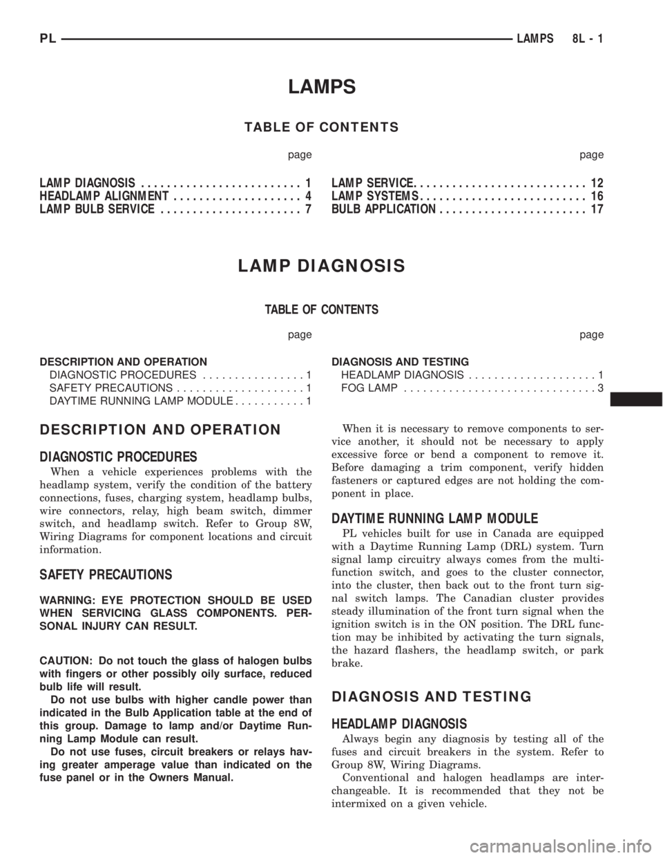
LAMPS
TABLE OF CONTENTS
page page
LAMP DIAGNOSIS......................... 1
HEADLAMP ALIGNMENT.................... 4
LAMP BULB SERVICE...................... 7LAMP SERVICE........................... 12
LAMP SYSTEMS.......................... 16
BULB APPLICATION....................... 17
LAMP DIAGNOSIS
TABLE OF CONTENTS
page page
DESCRIPTION AND OPERATION
DIAGNOSTIC PROCEDURES................1
SAFETY PRECAUTIONS....................1
DAYTIME RUNNING LAMP MODULE...........1DIAGNOSIS AND TESTING
HEADLAMP DIAGNOSIS....................1
FOG LAMP..............................3
DESCRIPTION AND OPERATION
DIAGNOSTIC PROCEDURES
When a vehicle experiences problems with the
headlamp system, verify the condition of the battery
connections, fuses, charging system, headlamp bulbs,
wire connectors, relay, high beam switch, dimmer
switch, and headlamp switch. Refer to Group 8W,
Wiring Diagrams for component locations and circuit
information.
SAFETY PRECAUTIONS
WARNING: EYE PROTECTION SHOULD BE USED
WHEN SERVICING GLASS COMPONENTS. PER-
SONAL INJURY CAN RESULT.
CAUTION: Do not touch the glass of halogen bulbs
with fingers or other possibly oily surface, reduced
bulb life will result.
Do not use bulbs with higher candle power than
indicated in the Bulb Application table at the end of
this group. Damage to lamp and/or Daytime Run-
ning Lamp Module can result.
Do not use fuses, circuit breakers or relays hav-
ing greater amperage value than indicated on the
fuse panel or in the Owners Manual.When it is necessary to remove components to ser-
vice another, it should not be necessary to apply
excessive force or bend a component to remove it.
Before damaging a trim component, verify hidden
fasteners or captured edges are not holding the com-
ponent in place.
DAYTIME RUNNING LAMP MODULE
PL vehicles built for use in Canada are equipped
with a Daytime Running Lamp (DRL) system. Turn
signal lamp circuitry always comes from the multi-
function switch, and goes to the cluster connector,
into the cluster, then back out to the front turn sig-
nal switch lamps. The Canadian cluster provides
steady illumination of the front turn signal when the
ignition switch is in the ON position. The DRL func-
tion may be inhibited by activating the turn signals,
the hazard flashers, the headlamp switch, or park
brake.
DIAGNOSIS AND TESTING
HEADLAMP DIAGNOSIS
Always begin any diagnosis by testing all of the
fuses and circuit breakers in the system. Refer to
Group 8W, Wiring Diagrams.
Conventional and halogen headlamps are inter-
changeable. It is recommended that they not be
intermixed on a given vehicle.
PLLAMPS 8L - 1
Page 309 of 1285
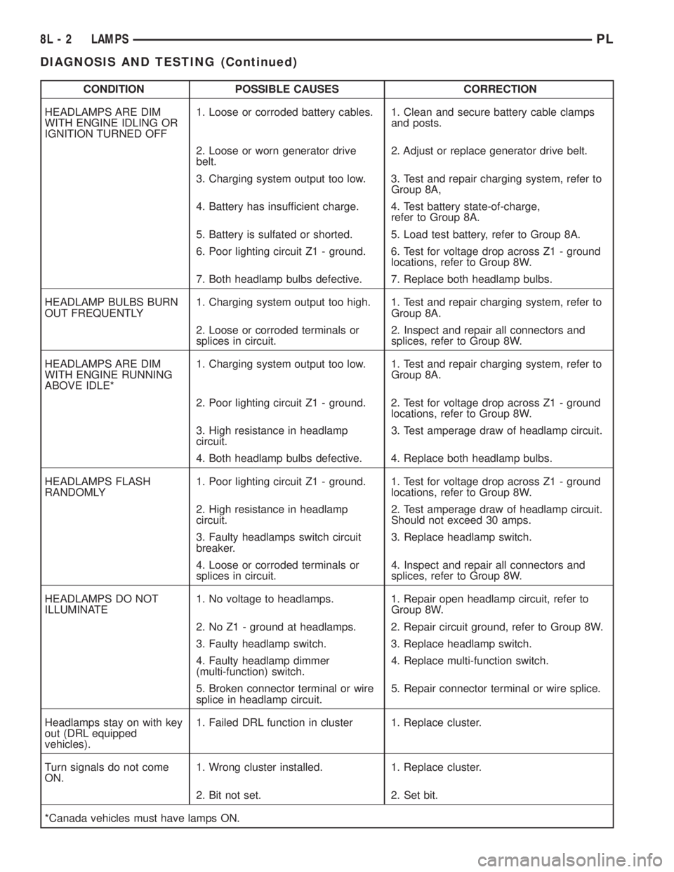
CONDITION POSSIBLE CAUSES CORRECTION
HEADLAMPS ARE DIM
WITH ENGINE IDLING OR
IGNITION TURNED OFF1. Loose or corroded battery cables. 1. Clean and secure battery cable clamps
and posts.
2. Loose or worn generator drive
belt.2. Adjust or replace generator drive belt.
3. Charging system output too low. 3. Test and repair charging system, refer to
Group 8A,
4. Battery has insufficient charge. 4. Test battery state-of-charge,
refer to Group 8A.
5. Battery is sulfated or shorted. 5. Load test battery, refer to Group 8A.
6. Poor lighting circuit Z1 - ground. 6. Test for voltage drop across Z1 - ground
locations, refer to Group 8W.
7. Both headlamp bulbs defective. 7. Replace both headlamp bulbs.
HEADLAMP BULBS BURN
OUT FREQUENTLY1. Charging system output too high. 1. Test and repair charging system, refer to
Group 8A.
2. Loose or corroded terminals or
splices in circuit.2. Inspect and repair all connectors and
splices, refer to Group 8W.
HEADLAMPS ARE DIM
WITH ENGINE RUNNING
ABOVE IDLE*1. Charging system output too low. 1. Test and repair charging system, refer to
Group 8A.
2. Poor lighting circuit Z1 - ground. 2. Test for voltage drop across Z1 - ground
locations, refer to Group 8W.
3. High resistance in headlamp
circuit.3. Test amperage draw of headlamp circuit.
4. Both headlamp bulbs defective. 4. Replace both headlamp bulbs.
HEADLAMPS FLASH
RANDOMLY1. Poor lighting circuit Z1 - ground. 1. Test for voltage drop across Z1 - ground
locations, refer to Group 8W.
2. High resistance in headlamp
circuit.2. Test amperage draw of headlamp circuit.
Should not exceed 30 amps.
3. Faulty headlamps switch circuit
breaker.3. Replace headlamp switch.
4. Loose or corroded terminals or
splices in circuit.4. Inspect and repair all connectors and
splices, refer to Group 8W.
HEADLAMPS DO NOT
ILLUMINATE1. No voltage to headlamps. 1. Repair open headlamp circuit, refer to
Group 8W.
2. No Z1 - ground at headlamps. 2. Repair circuit ground, refer to Group 8W.
3. Faulty headlamp switch. 3. Replace headlamp switch.
4. Faulty headlamp dimmer
(multi-function) switch.4. Replace multi-function switch.
5. Broken connector terminal or wire
splice in headlamp circuit.5. Repair connector terminal or wire splice.
Headlamps stay on with key
out (DRL equipped
vehicles).1. Failed DRL function in cluster 1. Replace cluster.
Turn signals do not come
ON.1. Wrong cluster installed. 1. Replace cluster.
2. Bit not set. 2. Set bit.
*Canada vehicles must have lamps ON.
8L - 2 LAMPSPL
DIAGNOSIS AND TESTING (Continued)
Page 310 of 1285
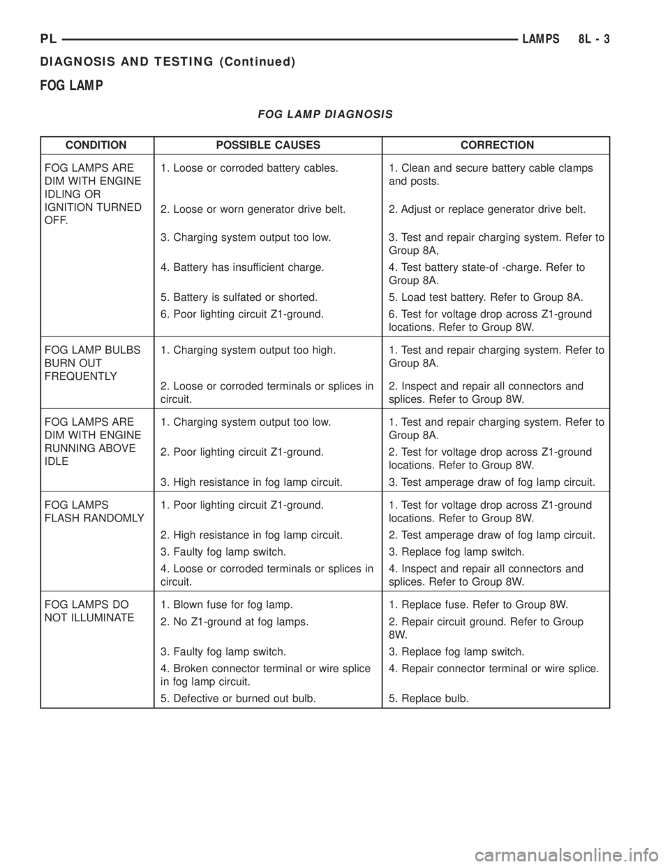
FOG LAMP
FOG LAMP DIAGNOSIS
CONDITION POSSIBLE CAUSES CORRECTION
FOG LAMPS ARE
DIM WITH ENGINE
IDLING OR
IGNITION TURNED
OFF.1. Loose or corroded battery cables. 1. Clean and secure battery cable clamps
and posts.
2. Loose or worn generator drive belt. 2. Adjust or replace generator drive belt.
3. Charging system output too low. 3. Test and repair charging system. Refer to
Group 8A,
4. Battery has insufficient charge. 4. Test battery state-of -charge. Refer to
Group 8A.
5. Battery is sulfated or shorted. 5. Load test battery. Refer to Group 8A.
6. Poor lighting circuit Z1-ground. 6. Test for voltage drop across Z1-ground
locations. Refer to Group 8W.
FOG LAMP BULBS
BURN OUT
FREQUENTLY1. Charging system output too high. 1. Test and repair charging system. Refer to
Group 8A.
2. Loose or corroded terminals or splices in
circuit.2. Inspect and repair all connectors and
splices. Refer to Group 8W.
FOG LAMPS ARE
DIM WITH ENGINE
RUNNING ABOVE
IDLE1. Charging system output too low. 1. Test and repair charging system. Refer to
Group 8A.
2. Poor lighting circuit Z1-ground. 2. Test for voltage drop across Z1-ground
locations. Refer to Group 8W.
3. High resistance in fog lamp circuit. 3. Test amperage draw of fog lamp circuit.
FOG LAMPS
FLASH RANDOMLY1. Poor lighting circuit Z1-ground. 1. Test for voltage drop across Z1-ground
locations. Refer to Group 8W.
2. High resistance in fog lamp circuit. 2. Test amperage draw of fog lamp circuit.
3. Faulty fog lamp switch. 3. Replace fog lamp switch.
4. Loose or corroded terminals or splices in
circuit.4. Inspect and repair all connectors and
splices. Refer to Group 8W.
FOG LAMPS DO
NOT ILLUMINATE1. Blown fuse for fog lamp. 1. Replace fuse. Refer to Group 8W.
2. No Z1-ground at fog lamps. 2. Repair circuit ground. Refer to Group
8W.
3. Faulty fog lamp switch. 3. Replace fog lamp switch.
4. Broken connector terminal or wire splice
in fog lamp circuit.4. Repair connector terminal or wire splice.
5. Defective or burned out bulb. 5. Replace bulb.
PLLAMPS 8L - 3
DIAGNOSIS AND TESTING (Continued)
Page 392 of 1285
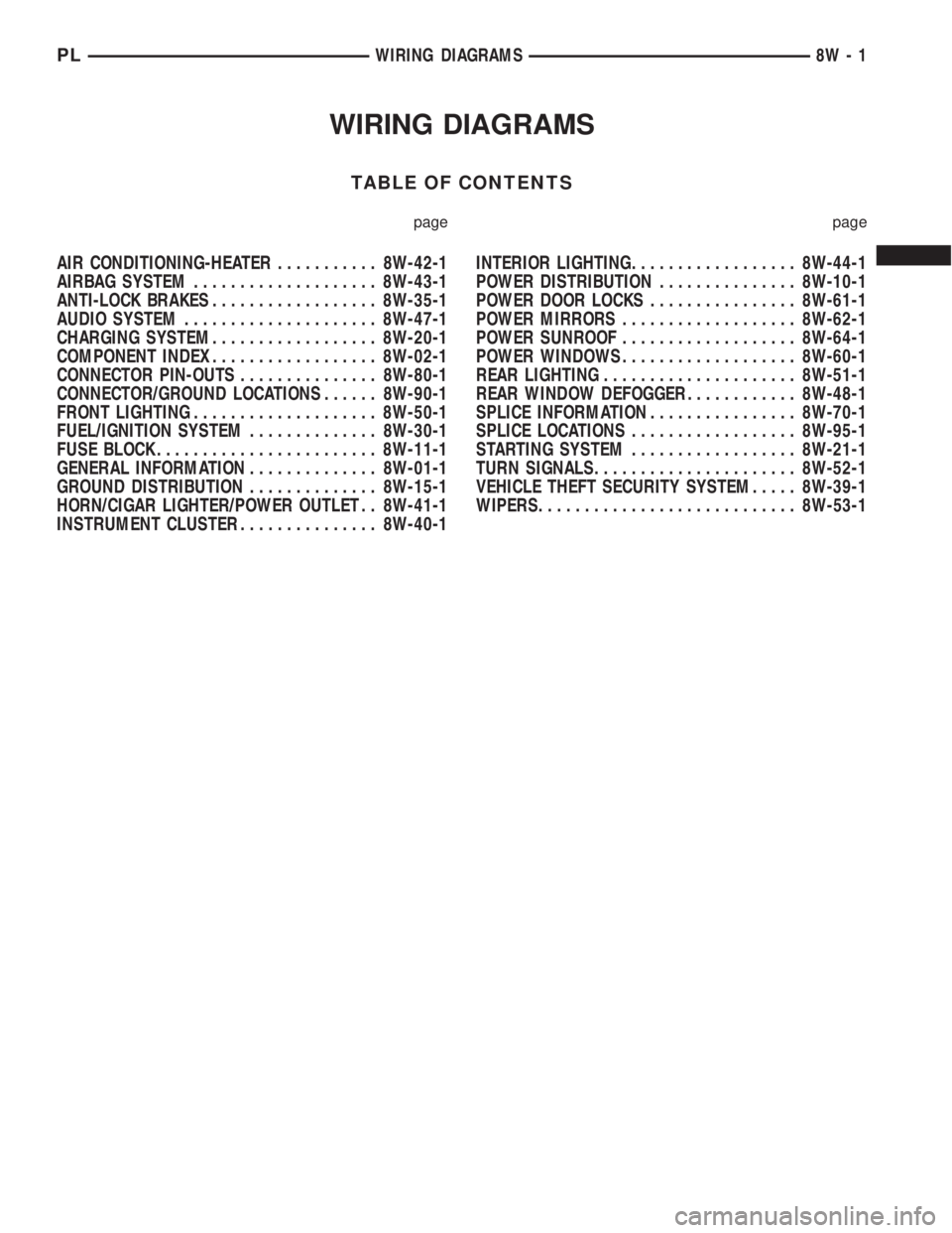
WIRING DIAGRAMS
TABLE OF CONTENTS
page page
AIR CONDITIONING-HEATER........... 8W-42-1
AIRBAG SYSTEM.................... 8W-43-1
ANTI-LOCK BRAKES.................. 8W-35-1
AUDIO SYSTEM..................... 8W-47-1
CHARGING SYSTEM.................. 8W-20-1
COMPONENT INDEX.................. 8W-02-1
CONNECTOR PIN-OUTS............... 8W-80-1
CONNECTOR/GROUND LOCATIONS...... 8W-90-1
FRONT LIGHTING.................... 8W-50-1
FUEL/IGNITION SYSTEM.............. 8W-30-1
FUSE BLOCK........................ 8W-11-1
GENERAL INFORMATION.............. 8W-01-1
GROUND DISTRIBUTION.............. 8W-15-1
HORN/CIGAR LIGHTER/POWER OUTLET . . 8W-41-1
INSTRUMENT CLUSTER............... 8W-40-1INTERIOR LIGHTING.................. 8W-44-1
POWER DISTRIBUTION............... 8W-10-1
POWER DOOR LOCKS................ 8W-61-1
POWER MIRRORS................... 8W-62-1
POWER SUNROOF................... 8W-64-1
POWER WINDOWS................... 8W-60-1
REAR LIGHTING..................... 8W-51-1
REAR WINDOW DEFOGGER............ 8W-48-1
SPLICE INFORMATION................ 8W-70-1
SPLICE LOCATIONS.................. 8W-95-1
STARTING SYSTEM.................. 8W-21-1
TURN SIGNALS...................... 8W-52-1
VEHICLE THEFT SECURITY SYSTEM..... 8W-39-1
WIPERS............................ 8W-53-1
PLWIRING DIAGRAMS 8W - 1
Page 398 of 1285
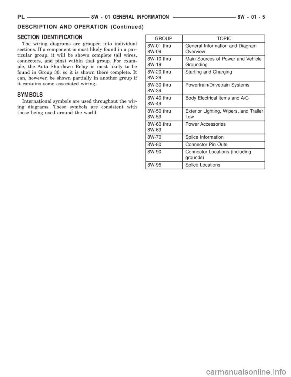
SECTION IDENTIFICATION
The wiring diagrams are grouped into individual
sections. If a component is most likely found in a par-
ticular group, it will be shown complete (all wires,
connectors, and pins) within that group. For exam-
ple, the Auto Shutdown Relay is most likely to be
found in Group 30, so it is shown there complete. It
can, however, be shown partially in another group if
it contains some associated wiring.
SYMBOLS
International symbols are used throughout the wir-
ing diagrams. These symbols are consistent with
those being used around the world.
GROUP TOPIC
8W-01 thru
8W-09General Information and Diagram
Overview
8W-10 thru
8W-19Main Sources of Power and Vehicle
Grounding
8W-20 thru
8W-29Starting and Charging
8W-30 thru
8W-39Powertrain/Drivetrain Systems
8W-40 thru
8W-49Body Electrical items and A/C
8W-50 thru
8W-59Exterior Lighting, Wipers, and Trailer
To w
8W-60 thru
8W-69Power Accessories
8W-70 Splice Information
8W-80 Connector Pin Outs
8W-90 Connector Locations (including
grounds)
8W-95 Splice Locations
PL8W - 01 GENERAL INFORMATION 8W - 01 - 5
DESCRIPTION AND OPERATION (Continued)
Page 470 of 1285
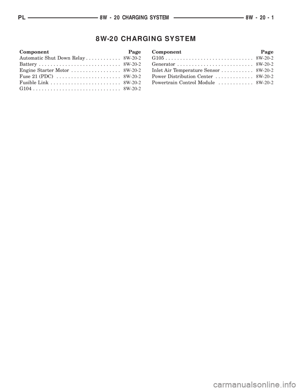
8W-20 CHARGING SYSTEM
Component Page
Automatic Shut Down Relay............8W-20-2
Battery............................8W-20-2
Engine Starter Motor.................8W-20-2
Fuse 21 (PDC)......................8W-20-2
Fusible Link........................8W-20-2
G104..............................8W-20-2Component Page
G105..............................8W-20-2
Generator..........................8W-20-2
Inlet Air Temperature Sensor...........8W-20-2
Power Distribution Center.............8W-20-2
Powertrain Control Module............8W-20-2
PL8W - 20 CHARGING SYSTEM 8W - 20 - 1
Page 471 of 1285

GENERATOR
ENGINE
STARTER
MOTOR
C18
GENERATOR
FIELD
DRIVER (+)POWERTRAIN
CONTROL
MODULE
K20
18
DG
21FUSE20A
21
34
36
POWER
DISTRIBUTION
CENTER BATTERY
A0
6
RD
A0 8RD
Z0
8
BK
Z1
10
BK
G105
A142
18
DG/OR
1C101
A142
18
DG/OR
S122
2
1
RELAY DOWN
SHUT
AUTOMATIC
A14
18
RD/WT
S106
A14
14
RD/WT
(IN PDC)
B(+)
S121
GROUNDSENSOR INLET AIR
TEMPERATURE
SENSOR
SIGNAL GROUNDSENSOR
SIGNAL SENSOR TEMPERATUREINLET AIR
VT/LG20 G31BK/LB20 K4
BK/LB20 K4
1 2
C243C252
S113
RD/WT18 A14
46C2
B(+) FUSED
SENSOR
TEMPERATURE
AIR
INLET
A11
12
BK
BK/GY8 A11
FUSIBLE
LINK
S125
BK/GY8 A11
BK/GY8 A11
G104
(8W-30-2)
(8W-30-6)
(8W-30-11) (8W-10-16)(8W-10-2)
(8W-10-3)
(8W-15-8)
(8W-10-17)
(8W-21-2)(8W-30-2)(8W-10-16)
(8W-10-17)
(8W-30-6)(8W-30-6) (8W-15-8)
8W - 20 - 2 8W-20 CHARGING SYSTEMPL
008W-10PLI02002
Page 842 of 1285
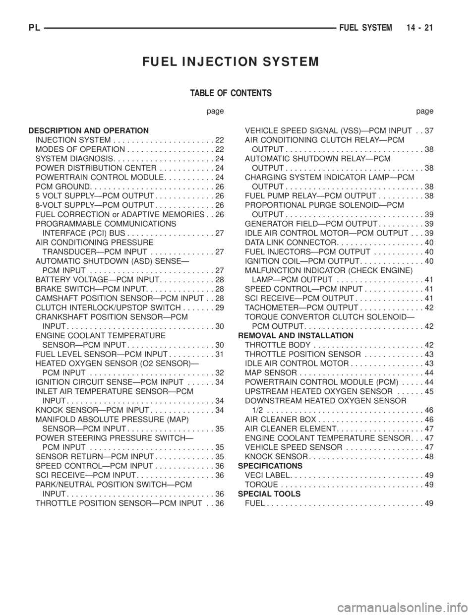
FUEL INJECTION SYSTEM
TABLE OF CONTENTS
page page
DESCRIPTION AND OPERATION
INJECTION SYSTEM......................22
MODES OF OPERATION...................22
SYSTEM DIAGNOSIS......................24
POWER DISTRIBUTION CENTER............24
POWERTRAIN CONTROL MODULE...........24
PCM GROUND...........................26
5 VOLT SUPPLYÐPCM OUTPUT.............26
8-VOLT SUPPLYÐPCM OUTPUT.............26
FUEL CORRECTION or ADAPTIVE MEMORIES . . 26
PROGRAMMABLE COMMUNICATIONS
INTERFACE (PCI) BUS...................27
AIR CONDITIONING PRESSURE
TRANSDUCERÐPCM INPUT..............27
AUTOMATIC SHUTDOWN (ASD) SENSEÐ
PCM INPUT...........................27
BATTERY VOLTAGEÐPCM INPUT............28
BRAKE SWITCHÐPCM INPUT...............28
CAMSHAFT POSITION SENSORÐPCM INPUT . . 28
CLUTCH INTERLOCK/UPSTOP SWITCH.......29
CRANKSHAFT POSITION SENSORÐPCM
INPUT................................30
ENGINE COOLANT TEMPERATURE
SENSORÐPCM INPUT...................30
FUEL LEVEL SENSORÐPCM INPUT..........31
HEATED OXYGEN SENSOR (O2 SENSOR)Ð
PCM INPUT...........................32
IGNITION CIRCUIT SENSEÐPCM INPUT......34
INLET AIR TEMPERATURE SENSORÐPCM
INPUT................................34
KNOCK SENSORÐPCM INPUT..............34
MANIFOLD ABSOLUTE PRESSURE (MAP)
SENSORÐPCM INPUT...................35
POWER STEERING PRESSURE SWITCHÐ
PCM INPUT...........................35
SENSOR RETURNÐPCM INPUT.............35
SPEED CONTROLÐPCM INPUT.............36
SCI RECEIVEÐPCM INPUT.................36
PARK/NEUTRAL POSITION SWITCHÐPCM
INPUT................................36
THROTTLE POSITION SENSORÐPCM INPUT . . 36VEHICLE SPEED SIGNAL (VSS)ÐPCM INPUT . . 37
AIR CONDITIONING CLUTCH RELAYÐPCM
OUTPUT..............................38
AUTOMATIC SHUTDOWN RELAYÐPCM
OUTPUT..............................38
CHARGING SYSTEM INDICATOR LAMPÐPCM
OUTPUT..............................38
FUEL PUMP RELAYÐPCM OUTPUT..........38
PROPORTIONAL PURGE SOLENOIDÐPCM
OUTPUT..............................39
GENERATOR FIELDÐPCM OUTPUT..........39
IDLE AIR CONTROL MOTORÐPCM OUTPUT . . . 39
DATA LINK CONNECTOR...................40
FUEL INJECTORSÐPCM OUTPUT...........40
IGNITION COILÐPCM OUTPUT..............40
MALFUNCTION INDICATOR (CHECK ENGINE)
LAMPÐPCM OUTPUT...................41
SPEED CONTROLÐPCM INPUT.............41
SCI RECEIVEÐPCM OUTPUT...............41
TACHOMETERÐPCM OUTPUT..............42
TORQUE CONVERTOR CLUTCH SOLENOIDÐ
PCM OUTPUT..........................42
REMOVAL AND INSTALLATION
THROTTLE BODY........................42
THROTTLE POSITION SENSOR.............43
IDLE AIR CONTROL MOTOR................43
MAP SENSOR...........................44
POWERTRAIN CONTROL MODULE (PCM).....44
UPSTREAM HEATED OXYGEN SENSOR......45
DOWNSTREAM HEATED OXYGEN SENSOR
1/2 ..................................46
AIR CLEANER BOX.......................46
AIR CLEANER ELEMENT...................47
ENGINE COOLANT TEMPERATURE SENSOR . . . 47
VEHICLE SPEED SENSOR.................47
KNOCK SENSOR.........................48
SPECIFICATIONS
VECI LABEL.............................49
TORQUE...............................49
SPECIAL TOOLS
FUEL..................................49
PLFUEL SYSTEM 14 - 21