2000 DODGE NEON cylinder head torque
[x] Cancel search: cylinder head torquePage 104 of 1285
(10) If the vehicle is equipped with antilock
brakes, carefully push the power brake booster for-
ward until the booster contacts the ABS ICU mount-
ing bracket.
(11) If the vehicle does not have antilock brakes,
carefully push the power brake booster forward one
to two inches being careful not to stretch the brake
lines from the master cylinder to the brakes.
(12) Remove the two nuts fastening the brake
pedal bracket to the instrument panel support (Fig.
40).
(13) Carefully remove the brake pedal assembly by
pulling the pedal bracket back toward the instru-
ment panel, releasing the bracket from the booster
studs. Next, tip the bracket down past the input rod,
guiding the rod through the gap left by the missing
brace removed in Step (8). Remove the brake pedal
assembly out from under the instrument panel.
(14) The pedal can be removed from it's bracket by
grinding off the peened end of the shaft, removing
the shaft, pedal and bushings. A service parts pack-
age is available to replace these items.
INSTALLATION
(1) If the pedal has been removed from it's
bracket, install the pedal, bushings and bolt-in-shaft
on the bracket using the available service parts pack-
age.
(2) Install the brake pedal assembly by tipping the
pedal bracket and guiding the power brake booster
mounting portion up past the booster input rod.
Guide the top of the bracket onto the studs protrud-
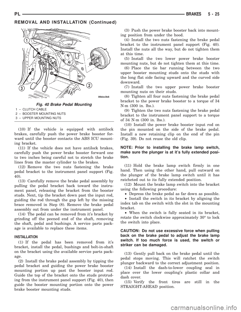
ing from the instrument panel support (Fig. 40), then
guide the booster mounting portion onto the power
brake booster mounting studs.(3) Push the power brake booster back into mount-
ing position from under the hood.
(4) Install the two nuts fastening the brake pedal
bracket to the instrument panel support (Fig. 40).
Install the nuts all the way, but do not tighten them
at this time.
(5) Install the two lower power brake booster
mounting nuts, but do not tighten them at this time.
(6) Place the tie bar running between the two
upper booster mounting studs onto the studs with
the long flat side facing upward and the curved side
downward.
(7) Install the two upper power brake booster
mounting nuts on their studs.
(8) Tighten all four nuts fastening the brake pedal
bracket to the power brake booster to a torque of 34
N´m (300 in. lbs.).
(9) Tighten the two nuts fastening the brake pedal
bracket to the instrument panel support to a torque
of 34 N´m (300 in. lbs.).
(10) Install the power brake booster input rod on
the pin mounted on the side of the brake pedal.
Install a new retaining clip on the end of the pin
(Fig. 39). Do not reuse the old clip.
NOTE: Prior to installing the brake lamp switch,
make sure the plunger is at it's fully extended posi-
tion.
(11) Hold the brake lamp switch firmly in one
hand. Then using the other hand, pull outward on
the plunger of the brake lamp switch until it has
ratcheted out to its fully extended position.
(12) Mount the brake lamp switch into the bracket
using the following procedure:
²Depress the brake pedal as far down as possible.
²Install the switch in its bracket by aligning the
index tab on the switch with the slot in the mounting
bracket.
²When the switch is fully seated in its bracket,
rotate the switch clockwise approximately 30É to lock
the switch into place.
CAUTION: Do not use excessive force when pulling
back on the brake pedal to adjust the brake lamp
switch. If too much force is used, the switch or
striker can be damaged.
(13) Gently pull back on the brake pedal until the
pedal stops moving. This will ratchet the switch
plunger backward to the correct adjustment position.
(14) Install the dash-to-lower coupling seal in
place over the lower coupling's plastic collar and
dash cover.
(15) Verify the front tires are still in the
STRAIGHT-AHEAD position.
Fig. 40 Brake Pedal Mounting
1 ± CLUTCH CABLE
2 ± BOOSTER MOUNTING NUTS
3 ± UPPER MOUNTING NUTS
PLBRAKES 5 - 25
REMOVAL AND INSTALLATION (Continued)
Page 142 of 1285
SPECIFICATIONS
BRAKE FLUID
The brake fluid used in this vehicle must conform
to DOT 3 specifications and SAE J1703 standards.
No other type of brake fluid is recommended or
approved for usage in the vehicle brake system. Use
only Mopar brake fluid or an equivalent from a
tightly sealed container.
CAUTION: Never use reclaimed brake fluid or fluid
from an container which has been left open. An
open container will absorb moisture from the air
and contaminate the fluid.
CAUTION: Never use any type of a petroleum-
based fluid in the brake hydraulic system. Use of
such type fluids will result in seal damage of the
vehicle brake hydraulic system causing a failure of
the vehicle brake system. Petroleum based fluids
would be items such as engine oil, transmission
fluid, power steering fluid, etc.
BRAKE ACTUATION SYSTEM
ACTUATION:
Vacuum Operated Power Brakes.....Standard
Hydraulic System.......Dual-Diagonally Split
BRAKE PEDAL:
Pedal Ratio..........................3.41
POWER BRAKE BOOSTER:
Make/Type..................Bosch/Vacuum
Mounting Studs.................. M8x1.25
Diaphragm Size/Type........ 205mmTandem
MASTER CYLINDER ASSEMBLY:
Type ........................Dual Tandem
Body Material...........Anodized Aluminum
Reservoir Material.............Polypropelene
MASTER CYLINDER BORE STROKE AND
SPLIT:
NonABS ..............22.23 mm x 34.0 mm
(0.875 in. x 1.34 in.)
ABS . . 23.82 mm x 34.0 mm (0.937 in. x 1.34 in.)
Displacement Split.................. 50/50MASTER CYLINDER FLUID OUTLET PORTS:
Tube Fitting Type...... SAE45ÉInverted Flare
W/ABS - Primary Tube Nut
Thread........................7/16 in.±24
W/ABS - Secondary Tube Nut
Thread........................ 3/8in.±24
W/O ABS - All Tube Nut Threads....7/16 in.±24
ABS HYDRAULIC CONTROL UNIT:
Hydraulic Tube Fitting
Type................ SAE45ÉInverted Flare
All Tube Nut Threads............7/16 in.±24
PROPORTIONING VALVE:
Material.......................Aluminum
Function.....Hydraulic Pressure Proportioning
BRAKE FASTENER TORQUE SPECIFICATIONS
DESCRIPTION TORQUE
BRAKE TUBES:
Tube Nuts............... 17N´m(145 in. lbs.)
MASTER CYLINDER:
Mounting Nuts.......... 28N´m(250 in. lbs.)
POWER BRAKE BOOSTER:
Mounting Nuts.......... 34N´m(300 in. lbs.)
DISC BRAKE CALIPER:
Caliper Banjo Bolt......... 48N´m(35ft.lbs.)
Guide Pin Bolts.......... 22N´m(192 in. lbs.)
Bleeder Screw........... 15N´m(125 in. lbs.)
WHEEL CYLINDER (REAR):
Mounting Bolts.......... 13N´m(115in.lbs.)
Bleeder Screw............ 10N´m(80in.lbs.)
DRUM BRAKE SHOE SUPPORT PLATE
(REAR):
Mounting Bolts........... 75N´m(55ft.lbs.)
DISC BRAKE ADAPTER (REAR):
Mounting Bolts........... 75N´m(55ft.lbs.)
HUB AND BEARING (REAR):
Retaining Nut.......... 217N´m(160 ft. lbs.)
PARKING BRAKE:
Lever Mounting Nuts..... 28N´m(250 in. lbs.)
TIRE AND WHEEL:
Wheel Mounting Nut...........109±150 N´m
(80±110 ft. lbs.)
INTEGRATED CONTROL UNIT:
Mounting Bolts........... 11N´m(97in.lbs.)
CAB Mounting bolts........ 2N´m(17in.lbs.)
Bracket-to-Frame Rail Bolts.......... 23N´m
(200 in. lbs.)
WHEEL SPEED SENSOR:
Head Mounting bolt...... 12N´m(105 in. lbs.)
PLBRAKES 5 - 63
Page 160 of 1285
(14) Refer to DISASSEMBLY AND ASSEMBLY in
this section of this group for the procedure on sepa-
rating and reattaching the CAB to the HCU.
INSTALLATION
(1) Install the ICU onto its mounting bracket.
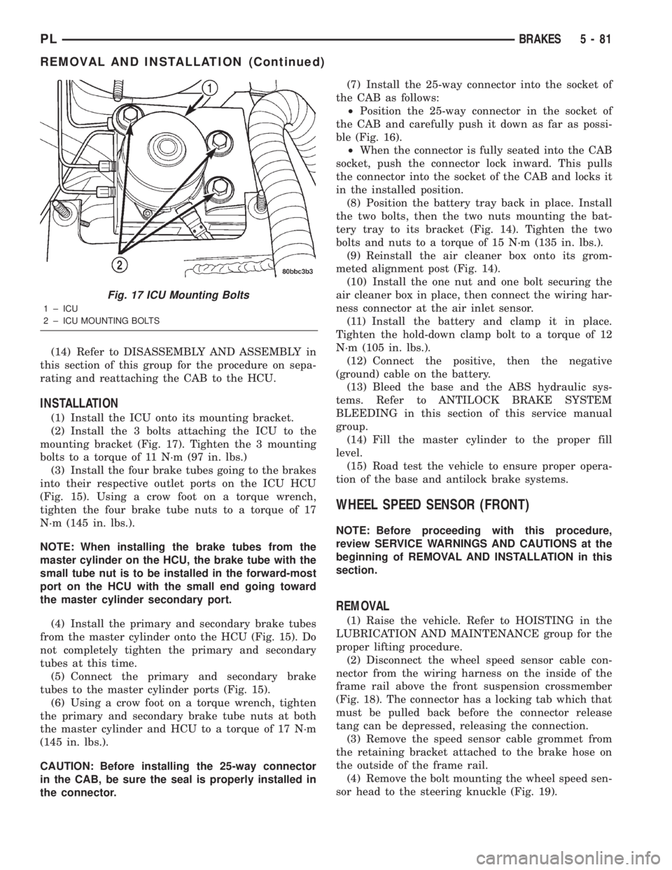
(2) Install the 3 bolts attaching the ICU to the
mounting bracket (Fig. 17). Tighten the 3 mounting
bolts to a torque of 11 N´m (97 in. lbs.)
(3) Install the four brake tubes going to the brakes
into their respective outlet ports on the ICU HCU
(Fig. 15). Using a crow foot on a torque wrench,
tighten the four brake tube nuts to a torque of 17
N´m (145 in. lbs.).
NOTE: When installing the brake tubes from the
master cylinder on the HCU, the brake tube with the
small tube nut is to be installed in the forward-most
port on the HCU with the small end going toward
the master cylinder secondary port.
(4) Install the primary and secondary brake tubes
from the master cylinder onto the HCU (Fig. 15). Do
not completely tighten the primary and secondary
tubes at this time.
(5) Connect the primary and secondary brake
tubes to the master cylinder ports (Fig. 15).
(6) Using a crow foot on a torque wrench, tighten
the primary and secondary brake tube nuts at both
the master cylinder and HCU to a torque of 17 N´m
(145 in. lbs.).
CAUTION: Before installing the 25-way connector
in the CAB, be sure the seal is properly installed in
the connector.(7) Install the 25-way connector into the socket of
the CAB as follows:
²Position the 25-way connector in the socket of
the CAB and carefully push it down as far as possi-
ble (Fig. 16).
²When the connector is fully seated into the CAB
socket, push the connector lock inward. This pulls
the connector into the socket of the CAB and locks it
in the installed position.
(8) Position the battery tray back in place. Install
the two bolts, then the two nuts mounting the bat-
tery tray to its bracket (Fig. 14). Tighten the two
bolts and nuts to a torque of 15 N´m (135 in. lbs.).
(9) Reinstall the air cleaner box onto its grom-
meted alignment post (Fig. 14).
(10) Install the one nut and one bolt securing the
air cleaner box in place, then connect the wiring har-
ness connector at the air inlet sensor.
(11) Install the battery and clamp it in place.
Tighten the hold-down clamp bolt to a torque of 12
N´m (105 in. lbs.).
(12) Connect the positive, then the negative
(ground) cable on the battery.
(13) Bleed the base and the ABS hydraulic sys-
tems. Refer to ANTILOCK BRAKE SYSTEM
BLEEDING in this section of this service manual
group.
(14) Fill the master cylinder to the proper fill
level.
(15) Road test the vehicle to ensure proper opera-
tion of the base and antilock brake systems.
WHEEL SPEED SENSOR (FRONT)
NOTE: Before proceeding with this procedure,
review SERVICE WARNINGS AND CAUTIONS at the
beginning of REMOVAL AND INSTALLATION in this
section.
REMOVAL
(1) Raise the vehicle. Refer to HOISTING in the
LUBRICATION AND MAINTENANCE group for the
proper lifting procedure.
(2) Disconnect the wheel speed sensor cable con-
nector from the wiring harness on the inside of the
frame rail above the front suspension crossmember
(Fig. 18). The connector has a locking tab which that
must be pulled back before the connector release
tang can be depressed, releasing the connection.
(3) Remove the speed sensor cable grommet from
the retaining bracket attached to the brake hose on
the outside of the frame rail.
(4) Remove the bolt mounting the wheel speed sen-
sor head to the steering knuckle (Fig. 19).
Fig. 17 ICU Mounting Bolts
1 ± ICU
2 ± ICU MOUNTING BOLTS
PLBRAKES 5 - 81
REMOVAL AND INSTALLATION (Continued)
Page 164 of 1285
SPECIFICATIONS
TONE WHEEL RUNOUT
FRONT TONE WHEEL:
Maximum Runout.........0.25 mm (0.009 in.)
REAR TONE WHEEL:
Maximum Runout.........0.25 mm (0.009 in.)
WHEEL SPEED SENSOR-TO-TONE WHEEL
CLEARANCE
FRONT WHEEL:
Minimum Clearance.......0.28 mm (0.011 in.)
Maximum Clearance.......1.42 mm (0.056 in.)
REAR WHEEL:
Minimum Clearance.......0.45 mm (0.018 in.)
Maximum Clearance.......1.12 mm (0.044 in.)
BRAKE FASTENER TORQUE SPECIFICATIONS
DESCRIPTION TORQUE
BRAKE TUBES:
Tube Nuts............... 17N´m(145 in. lbs.)
MASTER CYLINDER:
Mounting Nuts.......... 28N´m(250 in. lbs.)
POWER BRAKE BOOSTER:
Mounting Nuts.......... 34N´m(300 in. lbs.)
DISC BRAKE CALIPER:
Caliper Banjo Bolt......... 48N´m(35ft.lbs.)
Guide Pin Bolts.......... 22N´m(192 in. lbs.)
Bleeder Screw........... 15N´m(125 in. lbs.)
WHEEL CYLINDER (REAR):
Mounting Bolts.......... 13N´m(115in.lbs.)
Bleeder Screw............ 10N´m(80in.lbs.)
DRUM BRAKE SHOE SUPPORT PLATE
(REAR):
Mounting Bolts........... 75N´m(55ft.lbs.)
DISC BRAKE ADAPTER (REAR):
Mounting Bolts........... 75N´m(55ft.lbs.)
HUB AND BEARING (REAR):
Retaining Nut.......... 217N´m(160 ft. lbs.)
PARKING BRAKE:
Lever Mounting Nuts..... 28N´m(250 in. lbs.)
TIRE AND WHEEL:
Wheel Mounting Nut...........109±150 N´m
(80±110 ft. lbs.)
INTEGRATED CONTROL UNIT:
Mounting Bolts........... 11N´m(97in.lbs.)
CAB Mounting bolts........ 2N´m(17in.lbs.)
Bracket-to-Frame Rail Bolts.......... 23N´m
(200 in. lbs.)
WHEEL SPEED SENSOR:
Head Mounting bolt...... 12N´m(105 in. lbs.)
PLBRAKES 5 - 85
Page 236 of 1285
IGNITION SYSTEM
TABLE OF CONTENTS
page page
DESCRIPTION AND OPERATION
IGNITION SYSTEM........................1
SPARK PLUGS...........................1
SPARK PLUG CABLES.....................1
ELECTRONIC IGNITION COILS...............2
AUTOMATIC SHUTDOWN RELAY.............2
CRANKSHAFT POSITION SENSORÐPCM
INPUT................................3
CAMSHAFT POSITION SENSORÐPCM
INPUT................................4
KNOCK SENSOR..........................5
IGNITION SWITCH........................5
LOCK KEY CYLINDER......................5
IGNITION INTERLOCK.....................6
REMOVAL AND INSTALLATION
SPARK PLUG SERVICE....................6SPARK PLUG CABLE SERVICE..............6
IGNITION COIL...........................6
AUTOMATIC SHUTDOWN RELAY.............6
CAMSHAFT POSITION SENSOR..............6
CRANKSHAFT POSITION SENSOR............8
KNOCK SENSOR..........................8
IGNITION SWITCH........................8
LOCK KEY CYLINDER......................9
IGNITION INTERLOCK....................10
SPECIFICATIONS
VECI LABEL............................10
FIRING ORDERÐ2.0L....................10
TORQUE SPECIFICATION..................11
SPARK PLUG CABLE RESISTANCEÐSOHC....11
SPARK PLUG...........................11
IGNITION COIL..........................11
DESCRIPTION AND OPERATION
IGNITION SYSTEM
DESCRIPTION
The system's three main components are the coil
pack, crankshaft position sensor, and camshaft posi-
tion sensor.
OPERATION
Basic ignition timing is not adjustable.The
Powertrain Control Module (PCM) determines spark
advance. The 2.0L engines use a fixed ignition timing
system. The distributorless electronic ignition system
is referred to as the Direct Ignition System (DIS).
SPARK PLUGS
The 2.0L engines uses resistor spark plugs. For
spark plug identification and specifications, Refer to
the Specifications section at the end of this group.
Remove the spark plugs and examine them for
burned electrodes and fouled, cracked or broken por-
celain insulators. Keep plugs arranged in the order
in which they were removed from the engine. An iso-
lated plug displaying an abnormal condition indicates
that a problem exists in the corresponding cylinder.
Spark plugs that have low mileage may be cleaned
and reused if not otherwise defective. Refer to the
Spark Plug Condition section of this group. Aftercleaning, file the center electrode flat with a small
point file or jewelers file. Adjust the gap between the
electrodes (Fig. 1) to the dimensions specified in the
chart at the end of this section by bending the
ground electrode (just above the attachment weld)
with the appropriate tool.
Never apply any force between the electrode or
damage to the center electrode assembly will result.
Always tighten spark plugs to the specified torque.
Over tightening can cause distortion and damage.
Tighten spark plugs to 28 N´m (20 ft. lbs.) torque.
SPARK PLUG CABLES
Spark plug cables are sometimes referred to as sec-
ondary ignition wires. The wires transfer electrical
current from the coil pack to individual spark plugs
at each cylinder. The resistor type, nonmetallic spark
plug cables provide suppression of radio frequency
emissions from the ignition system.
Check the spark plug cable connections for good
contact at the coil and spark plugs. Terminals should
be fully seated. The nipples and spark plug covers
should be in good condition. Nipples should fit tightly
on the coil. Spark plug boot should completely cover
the spark plug hole in the cylinder head cover. Install
the boot until the terminal snaps over the spark
plug. A snap must be felt to ensure the spark plug
cable terminal engaged the spark plug.
PLIGNITION SYSTEM 8D - 1
Page 241 of 1285
IGNITION INTERLOCK
OPERATION
All vehicles equipped with automatic transaxles
have an interlock system. The system prevents shift-
ing the vehicle out of Park unless the ignition lock
cylinder is in the Off, Run or Start position. In addi-
tion, the operator cannot rotate the key to the lock
position unless the shifter is in the park position. On
vehicles equipped with floor shift refer to the - Tran-
saxle for Automatic Transmission Shifter/Ignition
Interlock.
REMOVAL AND INSTALLATION
SPARK PLUG SERVICE
Failure to route the cables properly could cause the
radio to reproduce ignition noise, cross ignition of the
spark plugs or short circuit the cables to ground.
REMOVAL
REMOVE CABLES FROM COIL FIRST.
Always remove the spark plug cable by grasping
the top of the spark plug insulator, turning the boot
1/2 turn and pulling straight up in a steady motion.
(1) Remove the spark plug using a quality socket
with a rubber or foam insert.
(2) Inspect the spark plug condition.
INSTALLATION
(1) To avoid cross threading, start the spark plug
into the cylinder head by hand.
(2) Tighten spark plugs to 28 N´m (20 ft. lbs.)
torque.
(3) Install spark plug insulators over spark plugs.
Ensure the top of the spark plug insulator covers the
upper end of the spark plug tube.
Reconnect to coil.
SPARK PLUG CABLE SERVICE
Failure to route the cables properly could cause the
radio to reproduce ignition noise, cross ignition of the
spark plugs or short circuit the cables to ground.
REMOVAL
Remove spark plug cable from coil first.
Always remove the spark plug cable by grasping
the top of the spark plug insulator, turning the boot
1/2 turn and pulling straight up in a steady motion.
INSTALLATION
Install spark plug insulators over spark plugs.
Ensure the top of the spark plug insulator covers the
upper end of the spark plug tube. The connect theother end to coil pack. Be sure that dual plastic clip
holds the cables off of the valve cover.
IGNITION COIL
The electronic ignition coil pack attaches directly
to the valve cover (Fig. 11).
REMOVAL
(1) Disconnect electrical connector from coil pack
(Fig. 10).
(2) Remove coil pack mounting bolts.
(3) Remove coil pack.
INSTALLATION
(1) Install coil pack on valve cover.
(2) Transfer spark plug cables to new coil pack.
The coil pack towers are numbered with the cylinder
identification. Be sure the ignition cables snap onto
the towers.
AUTOMATIC SHUTDOWN RELAY
The relay is located in the Power Distribution Cen-
ter (PDC) (Fig. 12). The PDC is located next to the
battery in the engine compartment. For the location
of the relay within the PDC, refer to the PDC cover
for location. Check electrical terminals for corrosion
and repair as necessary.
CAMSHAFT POSITION SENSOR
The camshaft position sensor is mounted to the
rear of the cylinder head (Fig. 13).
Fig. 10 Electronic Ignition Coil Connector
1 ± COIL
2 ± LOCKING TAB
8D - 6 IGNITION SYSTEMPL
DESCRIPTION AND OPERATION (Continued)
Page 242 of 1285
REMOVAL
(1) Remove brake booster hose and electrical con-
nector from holders on end of cylinder head cover
and reposition.
(2) Disconnect electrical connectors from camshaft
position sensor.
(3) Remove camshaft position sensor mounting
screws. Remove sensor.
(4) Loosen screw attaching target magnet to rear
of camshaft (Fig. 14).
INSTALLATION
The target magnet has two locating dowels that fit
into machined locating holes in end of the camshaft.
(1) Install target magnet in end of camshaft.
Tighten mounting screw to 3.4 N´m (30 in. lbs.)
torque.
(2) Install camshaft position sensor. Tighten sensor
mounting screws to 9 N´m (80 in. lbs.) torque.
(3) Place brake booster hose and electrical harness
in holders on end of valve cover.
(4) Attach electrical connectors to camshaft posi-
tion sensor.
Fig. 11 Electronic Ignition Coil Pack
1 ± IGNITION COILS
2 ± SPARK PLUG CABLE
3 ± SPARK PLUG INSULATOR
Fig. 12 Power Distribution Center (PDC)
Fig. 13 Camshaft Position Sensor Location
Fig. 14 Target Magnet Removal/Installation
1 ± TARGET MAGNET
2 ± MOUNTING BOLT
3 ± REAR OF CYLINDER HEAD
PLIGNITION SYSTEM 8D - 7
REMOVAL AND INSTALLATION (Continued)
Page 350 of 1285
(3) Install center console assembly. Refer to Group
23 Body, Floor Console Removal and Installation.
(4) Do not connect battery negative cable. Refer to
Diagnosis and Testing for Airbag System Test for the
proper procedures.
CLOCKSPRING
WARNING: DISCONNECT AND ISOLATE THE BAT-
TERY NEGATIVE (GROUND) CABLE BEFORE
BEGINNING ANY AIRBAG SYSTEM COMPONENT
REMOVAL OR INSTALLATION PROCEDURE. THIS
WILL DISABLE THE AIRBAG SYSTEM. FAILURE TO
DISCONNECT BATTERY COULD RESULT IN ACCI-
DENTAL AIRBAG DEPLOYMENT AND POSSIBLE
PERSONAL INJURY.
ALLOW SYSTEM CAPACITOR TO DISCHARGE
FOR 1 MINUTE BEFORE REMOVING ANY AIRBAG
COMPONENTS.
REMOVAL
(1) Place the front road wheels in the straight
ahead position then:
²Rotate the steering wheel half turn (180
degrees) to the right (clockwise).
²Lock column with ignition lock cylinder.
(2) Disconnect and isolate the battery negative
cable (Fig. 4).
(3) Wait one minute for the reserve capacitor to
discharge before removing non-deployed module.
(4) Remove steering wheel. Refer to Steering
Wheel Removal and Installation in this section.
(5) Remove upper and lower steering column
shrouds to gain access to clockspring wiring. Refer to
Group 8E Instrument Panel Systems, Steering Col-
umn Shroud Removal and Installation.
(6) Remove multi-function switch. Refer to Group
8J-Turn Signal and Hazard Warning Systems, Multi-
Function Switch Removal and Installation.
(7) Disconnect the 7-way connector between the
clockspring and the instrument panel wiring harness
at the base of the clockspring.
(8) Remove clockspring by lifting the top latch tab
up slightly to guide it over the lock housing (Fig. 7).
The clockspring cannot be repaired, and must be
replaced if faulty.
(9) Rotate clockspring rotor a half turn (180
degrees) to the left (counter clockwise).
(10) Lock the clockspring rotor in the center posi-
tion as follows: Insert a paper clip wire through the
hole in the rotor at the 10 O'clock position and bend
to prevent it from falling out.
INSTALLATION
(1) Confirm that:²The steering wheel position is a half turn (180
degrees) to the right (clockwise)
²The column is locked with the ignition cylinder
lock.
²Check that the turn signal stalk is in the neu-
tral position
²When reusing the clockspring, remove locking
wire and rotate clockspring rotor one half turn (180
degrees) to the right (clockwise). Locate the clock-
spring on the steering shaft and push down on the
rotor until the clockspring is fully seated on the
steering column.
²When installing a new clockspring, position the
front wheels straight a head. Remove grenade pin.
Rotate clockspring rotor one half turn (180 degrees)
to the right (clockwise).
(2) Connect the clockspring to the instrument
panel harness, ensure wiring is properly routed.
Then check that the connectors, locking tabs are
properly engaged and the halo lamp wire is in posi-
tion.
(3) Install steering column shrouds. Be sure all
wires are inside of shrouds.
(4) Install steering wheel ensuring the flats on hub
align with the clockspring. Pull the horn, airbag and
speed control leads through the larger slot. Ensure
leads do not get pinched under the steering wheel.
(5) Route speed control wires under and behind
the airbag module mounting tabs.
(6) Connect the horn lead wire and the airbag lead
wire to the airbag module.
(7) Install the airbag module and tighten bolts to
12 to 14 N´m (105 to 125 in. lbs.) torque.
(8) Connect the speed control wires to the switches
and install switches. Tighten screws to 2 N´m (20 in.
lbs.) torque.
Fig. 7 Clockspring Latch Hooks
1 ± CLOCKSPRING
2 ± LATCH HOOKS
3 ± STEERING COLUMN
PLPASSIVE RESTRAINT SYSTEMS 8M - 5
REMOVAL AND INSTALLATION (Continued)