2000 DODGE NEON engine overheat
[x] Cancel search: engine overheatPage 168 of 1285
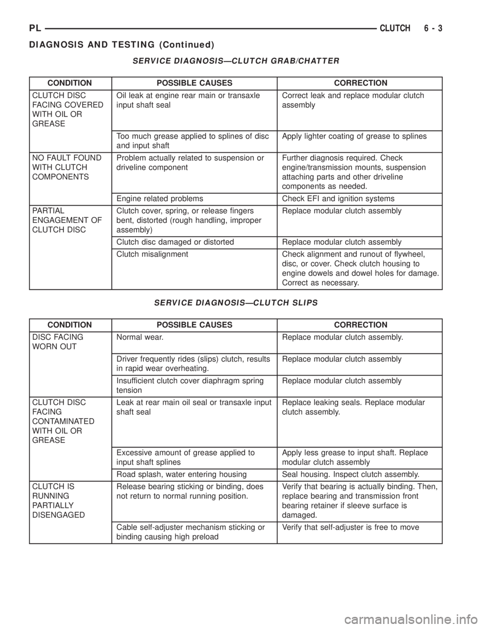
SERVICE DIAGNOSISÐCLUTCH GRAB/CHATTER
CONDITION POSSIBLE CAUSES CORRECTION
CLUTCH DISC
FACING COVERED
WITH OIL OR
GREASEOil leak at engine rear main or transaxle
input shaft sealCorrect leak and replace modular clutch
assembly
Too much grease applied to splines of disc
and input shaftApply lighter coating of grease to splines
NO FAULT FOUND
WITH CLUTCH
COMPONENTSProblem actually related to suspension or
driveline componentFurther diagnosis required. Check
engine/transmission mounts, suspension
attaching parts and other driveline
components as needed.
Engine related problems Check EFI and ignition systems
PARTIAL
ENGAGEMENT OF
CLUTCH DISCClutch cover, spring, or release fingers
bent, distorted (rough handling, improper
assembly)Replace modular clutch assembly
Clutch disc damaged or distorted Replace modular clutch assembly
Clutch misalignment Check alignment and runout of flywheel,
disc, or cover. Check clutch housing to
engine dowels and dowel holes for damage.
Correct as necessary.
SERVICE DIAGNOSISÐCLUTCH SLIPS
CONDITION POSSIBLE CAUSES CORRECTION
DISC FACING
WORN OUTNormal wear. Replace modular clutch assembly.
Driver frequently rides (slips) clutch, results
in rapid wear overheating.Replace modular clutch assembly
Insufficient clutch cover diaphragm spring
tensionReplace modular clutch assembly
CLUTCH DISC
FACING
CONTAMINATED
WITH OIL OR
GREASELeak at rear main oil seal or transaxle input
shaft sealReplace leaking seals. Replace modular
clutch assembly.
Excessive amount of grease applied to
input shaft splinesApply less grease to input shaft. Replace
modular clutch assembly
Road splash, water entering housing Seal housing. Inspect clutch assembly.
CLUTCH IS
RUNNING
PARTIALLY
DISENGAGEDRelease bearing sticking or binding, does
not return to normal running position.Verify that bearing is actually binding. Then,
replace bearing and transmission front
bearing retainer if sleeve surface is
damaged.
Cable self-adjuster mechanism sticking or
binding causing high preloadVerify that self-adjuster is free to move
PLCLUTCH 6 - 3
DIAGNOSIS AND TESTING (Continued)
Page 186 of 1285
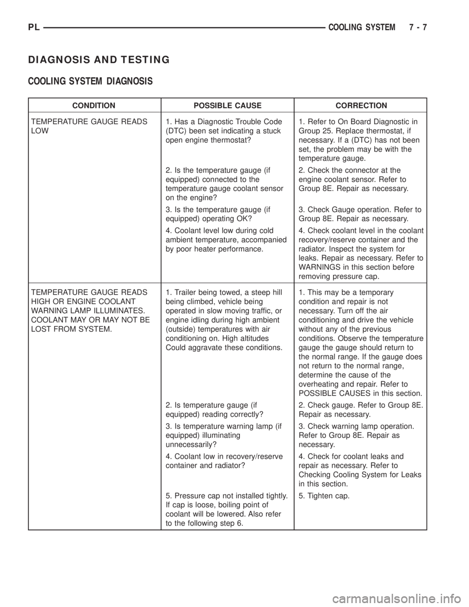
DIAGNOSIS AND TESTING
COOLING SYSTEM DIAGNOSIS
CONDITION POSSIBLE CAUSE CORRECTION
TEMPERATURE GAUGE READS
LOW1. Has a Diagnostic Trouble Code
(DTC) been set indicating a stuck
open engine thermostat?1. Refer to On Board Diagnostic in
Group 25. Replace thermostat, if
necessary. If a (DTC) has not been
set, the problem may be with the
temperature gauge.
2. Is the temperature gauge (if
equipped) connected to the
temperature gauge coolant sensor
on the engine?2. Check the connector at the
engine coolant sensor. Refer to
Group 8E. Repair as necessary.
3. Is the temperature gauge (if
equipped) operating OK?3. Check Gauge operation. Refer to
Group 8E. Repair as necessary.
4. Coolant level low during cold
ambient temperature, accompanied
by poor heater performance.4. Check coolant level in the coolant
recovery/reserve container and the
radiator. Inspect the system for
leaks. Repair as necessary. Refer to
WARNINGS in this section before
removing pressure cap.
TEMPERATURE GAUGE READS
HIGH OR ENGINE COOLANT
WARNING LAMP ILLUMINATES.
COOLANT MAY OR MAY NOT BE
LOST FROM SYSTEM.1. Trailer being towed, a steep hill
being climbed, vehicle being
operated in slow moving traffic, or
engine idling during high ambient
(outside) temperatures with air
conditioning on. High altitudes
Could aggravate these conditions.1. This may be a temporary
condition and repair is not
necessary. Turn off the air
conditioning and drive the vehicle
without any of the previous
conditions. Observe the temperature
gauge the gauge should return to
the normal range. If the gauge does
not return to the normal range,
determine the cause of the
overheating and repair. Refer to
POSSIBLE CAUSES in this section.
2. Is temperature gauge (if
equipped) reading correctly?2. Check gauge. Refer to Group 8E.
Repair as necessary.
3. Is temperature warning lamp (if
equipped) illuminating
unnecessarily?3. Check warning lamp operation.
Refer to Group 8E. Repair as
necessary.
4. Coolant low in recovery/reserve
container and radiator?4. Check for coolant leaks and
repair as necessary. Refer to
Checking Cooling System for Leaks
in this section.
5. Pressure cap not installed tightly.
If cap is loose, boiling point of
coolant will be lowered. Also refer
to the following step 6.5. Tighten cap.
PLCOOLING SYSTEM 7 - 7
Page 189 of 1285
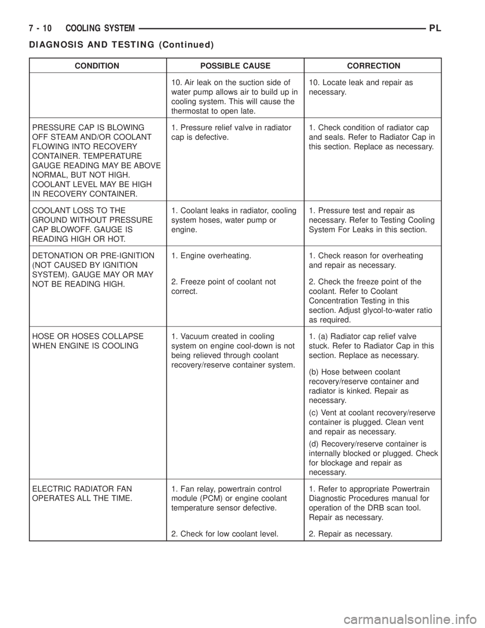
CONDITION POSSIBLE CAUSE CORRECTION
10. Air leak on the suction side of
water pump allows air to build up in
cooling system. This will cause the
thermostat to open late.10. Locate leak and repair as
necessary.
PRESSURE CAP IS BLOWING
OFF STEAM AND/OR COOLANT
FLOWING INTO RECOVERY
CONTAINER. TEMPERATURE
GAUGE READING MAY BE ABOVE
NORMAL, BUT NOT HIGH.
COOLANT LEVEL MAY BE HIGH
IN RECOVERY CONTAINER.1. Pressure relief valve in radiator
cap is defective.1. Check condition of radiator cap
and seals. Refer to Radiator Cap in
this section. Replace as necessary.
COOLANT LOSS TO THE
GROUND WITHOUT PRESSURE
CAP BLOWOFF. GAUGE IS
READING HIGH OR HOT.1. Coolant leaks in radiator, cooling
system hoses, water pump or
engine.1. Pressure test and repair as
necessary. Refer to Testing Cooling
System For Leaks in this section.
DETONATION OR PRE-IGNITION
(NOT CAUSED BY IGNITION
SYSTEM). GAUGE MAY OR MAY
NOT BE READING HIGH.1. Engine overheating. 1. Check reason for overheating
and repair as necessary.
2. Freeze point of coolant not
correct.2. Check the freeze point of the
coolant. Refer to Coolant
Concentration Testing in this
section. Adjust glycol-to-water ratio
as required.
HOSE OR HOSES COLLAPSE
WHEN ENGINE IS COOLING1. Vacuum created in cooling
system on engine cool-down is not
being relieved through coolant
recovery/reserve container system.1. (a) Radiator cap relief valve
stuck. Refer to Radiator Cap in this
section. Replace as necessary.
(b) Hose between coolant
recovery/reserve container and
radiator is kinked. Repair as
necessary.
(c) Vent at coolant recovery/reserve
container is plugged. Clean vent
and repair as necessary.
(d) Recovery/reserve container is
internally blocked or plugged. Check
for blockage and repair as
necessary.
ELECTRIC RADIATOR FAN
OPERATES ALL THE TIME.1. Fan relay, powertrain control
module (PCM) or engine coolant
temperature sensor defective.1. Refer to appropriate Powertrain
Diagnostic Procedures manual for
operation of the DRB scan tool.
Repair as necessary.
2. Check for low coolant level. 2. Repair as necessary.
7 - 10 COOLING SYSTEMPL
DIAGNOSIS AND TESTING (Continued)
Page 190 of 1285
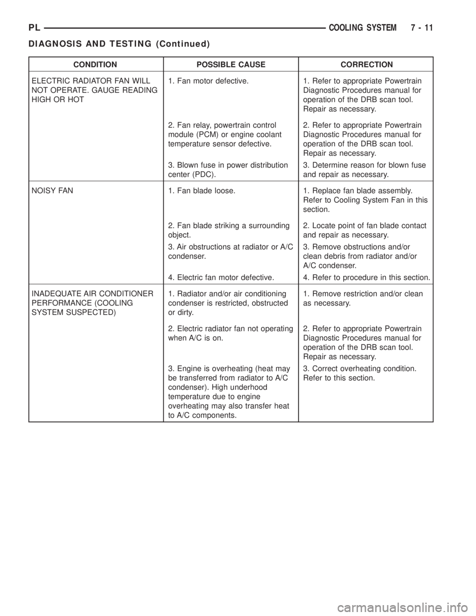
CONDITION POSSIBLE CAUSE CORRECTION
ELECTRIC RADIATOR FAN WILL
NOT OPERATE. GAUGE READING
HIGH OR HOT1. Fan motor defective. 1. Refer to appropriate Powertrain
Diagnostic Procedures manual for
operation of the DRB scan tool.
Repair as necessary.
2. Fan relay, powertrain control
module (PCM) or engine coolant
temperature sensor defective.2. Refer to appropriate Powertrain
Diagnostic Procedures manual for
operation of the DRB scan tool.
Repair as necessary.
3. Blown fuse in power distribution
center (PDC).3. Determine reason for blown fuse
and repair as necessary.
NOISY FAN 1. Fan blade loose. 1. Replace fan blade assembly.
Refer to Cooling System Fan in this
section.
2. Fan blade striking a surrounding
object.2. Locate point of fan blade contact
and repair as necessary.
3. Air obstructions at radiator or A/C
condenser.3. Remove obstructions and/or
clean debris from radiator and/or
A/C condenser.
4. Electric fan motor defective. 4. Refer to procedure in this section.
INADEQUATE AIR CONDITIONER
PERFORMANCE (COOLING
SYSTEM SUSPECTED)1. Radiator and/or air conditioning
condenser is restricted, obstructed
or dirty.1. Remove restriction and/or clean
as necessary.
2. Electric radiator fan not operating
when A/C is on.2. Refer to appropriate Powertrain
Diagnostic Procedures manual for
operation of the DRB scan tool.
Repair as necessary.
3. Engine is overheating (heat may
be transferred from radiator to A/C
condenser). High underhood
temperature due to engine
overheating may also transfer heat
to A/C components.3. Correct overheating condition.
Refer to this section.
PLCOOLING SYSTEM 7 - 11
DIAGNOSIS AND TESTING (Continued)
Page 191 of 1285
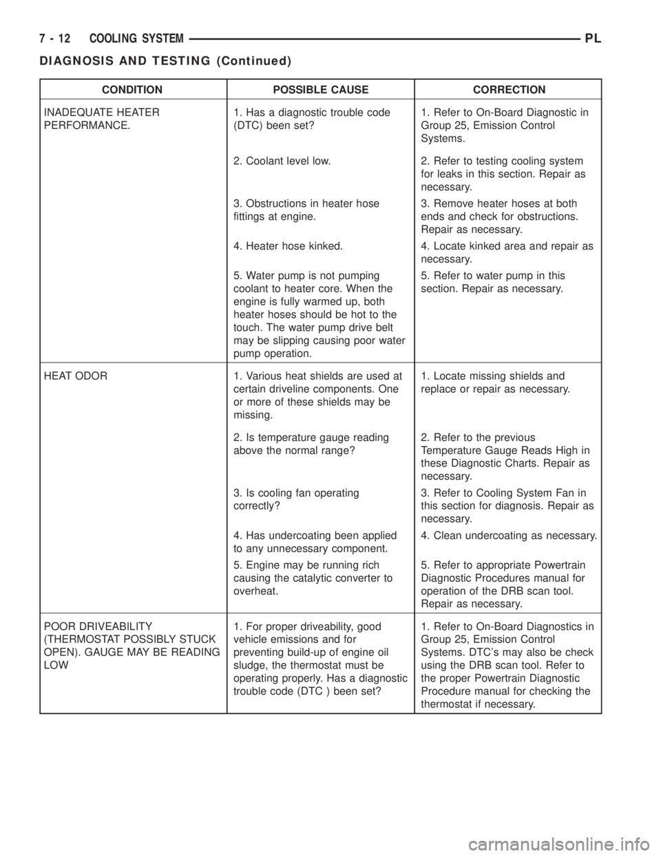
CONDITION POSSIBLE CAUSE CORRECTION
INADEQUATE HEATER
PERFORMANCE.1. Has a diagnostic trouble code
(DTC) been set?1. Refer to On-Board Diagnostic in
Group 25, Emission Control
Systems.
2. Coolant level low. 2. Refer to testing cooling system
for leaks in this section. Repair as
necessary.
3. Obstructions in heater hose
fittings at engine.3. Remove heater hoses at both
ends and check for obstructions.
Repair as necessary.
4. Heater hose kinked. 4. Locate kinked area and repair as
necessary.
5. Water pump is not pumping
coolant to heater core. When the
engine is fully warmed up, both
heater hoses should be hot to the
touch. The water pump drive belt
may be slipping causing poor water
pump operation.5. Refer to water pump in this
section. Repair as necessary.
HEAT ODOR 1. Various heat shields are used at
certain driveline components. One
or more of these shields may be
missing.1. Locate missing shields and
replace or repair as necessary.
2. Is temperature gauge reading
above the normal range?2. Refer to the previous
Temperature Gauge Reads High in
these Diagnostic Charts. Repair as
necessary.
3. Is cooling fan operating
correctly?3. Refer to Cooling System Fan in
this section for diagnosis. Repair as
necessary.
4. Has undercoating been applied
to any unnecessary component.4. Clean undercoating as necessary.
5. Engine may be running rich
causing the catalytic converter to
overheat.5. Refer to appropriate Powertrain
Diagnostic Procedures manual for
operation of the DRB scan tool.
Repair as necessary.
POOR DRIVEABILITY
(THERMOSTAT POSSIBLY STUCK
OPEN). GAUGE MAY BE READING
LOW1. For proper driveability, good
vehicle emissions and for
preventing build-up of engine oil
sludge, the thermostat must be
operating properly. Has a diagnostic
trouble code (DTC ) been set?1. Refer to On-Board Diagnostics in
Group 25, Emission Control
Systems. DTC's may also be check
using the DRB scan tool. Refer to
the proper Powertrain Diagnostic
Procedure manual for checking the
thermostat if necessary.
7 - 12 COOLING SYSTEMPL
DIAGNOSIS AND TESTING (Continued)
Page 226 of 1285
FEED CIRCUIT
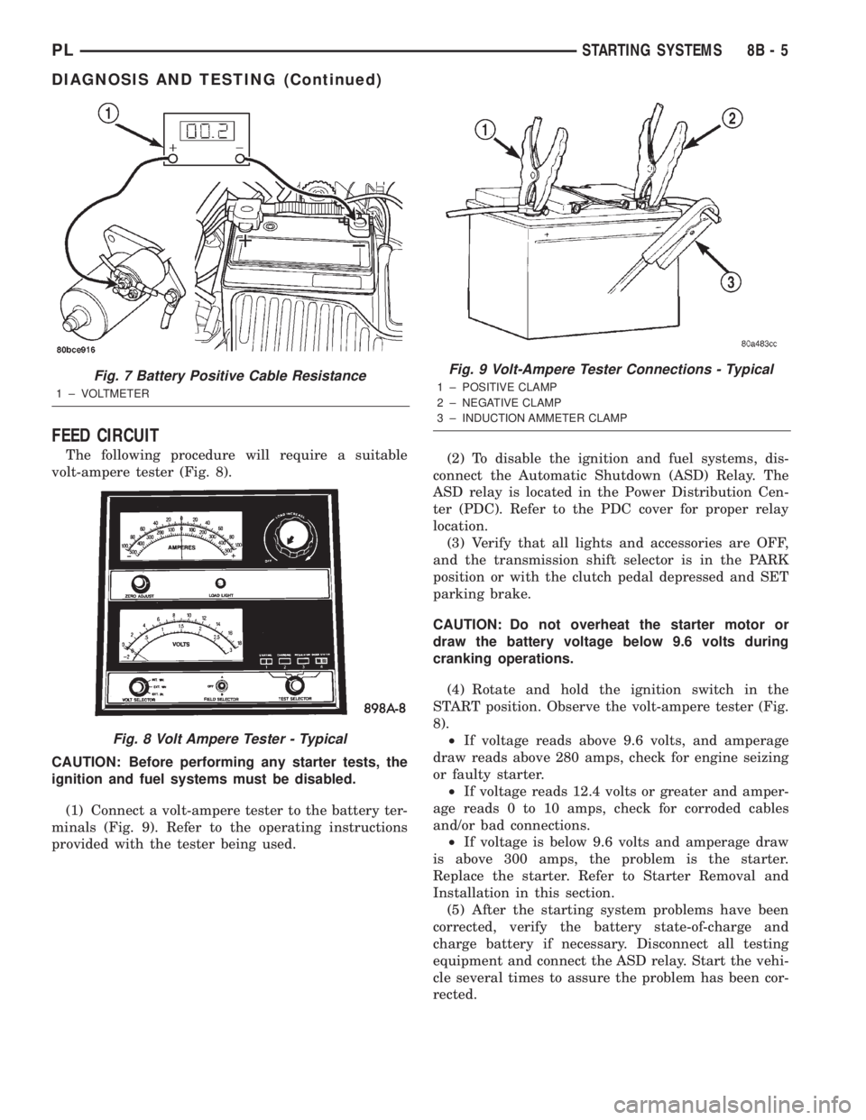
The following procedure will require a suitable
volt-ampere tester (Fig. 8).
CAUTION: Before performing any starter tests, the
ignition and fuel systems must be disabled.
(1) Connect a volt-ampere tester to the battery ter-
minals (Fig. 9). Refer to the operating instructions
provided with the tester being used.(2) To disable the ignition and fuel systems, dis-
connect the Automatic Shutdown (ASD) Relay. The
ASD relay is located in the Power Distribution Cen-
ter (PDC). Refer to the PDC cover for proper relay
location.
(3) Verify that all lights and accessories are OFF,
and the transmission shift selector is in the PARK
position or with the clutch pedal depressed and SET
parking brake.
CAUTION: Do not overheat the starter motor or
draw the battery voltage below 9.6 volts during
cranking operations.
(4) Rotate and hold the ignition switch in the
START position. Observe the volt-ampere tester (Fig.
8).
²If voltage reads above 9.6 volts, and amperage
draw reads above 280 amps, check for engine seizing
or faulty starter.
²If voltage reads 12.4 volts or greater and amper-
age reads 0 to 10 amps, check for corroded cables
and/or bad connections.
²If voltage is below 9.6 volts and amperage draw
is above 300 amps, the problem is the starter.
Replace the starter. Refer to Starter Removal and
Installation in this section.
(5) After the starting system problems have been
corrected, verify the battery state-of-charge and
charge battery if necessary. Disconnect all testing
equipment and connect the ASD relay. Start the vehi-
cle several times to assure the problem has been cor-
rected.
Fig. 7 Battery Positive Cable Resistance
1 ± VOLTMETER
Fig. 8 Volt Ampere Tester - Typical
Fig. 9 Volt-Ampere Tester Connections - Typical
1 ± POSITIVE CLAMP
2 ± NEGATIVE CLAMP
3 ± INDUCTION AMMETER CLAMP
PLSTARTING SYSTEMS 8B - 5
DIAGNOSIS AND TESTING (Continued)
Page 823 of 1285
REFORMULATED GASOLINE
Many areas of the country require the use of
cleaner burning gasoline referred to as ªreformulat-
edº gasoline. Reformulated gasoline contain oxygen-
ates, and are specifically blended to reduce vehicle
emissions and improve air quality.
DaimlerChrysler Corporation strongly supports the
use of reformulated gasoline. Properly blended refor-
mulated gasoline will provide excellent performance
and durability for the engine and fuel system compo-
nents.
GASOLINE/OXYGENATE BLENDS
Some fuel suppliers blend unleaded gasoline with
oxygenates such as 10% ethanol, MTBE, and ETBE.
Oxygenates are required in some areas of the country
during the winter months to reduce carbon monoxide
emissions. Fuels blended with these oxygenates may
be used in your vehicle.
CAUTION: DO NOT use gasoline containing METH-
ANOL. Gasoline containing methanol may damage
critical fuel system components.
MMT
MMT is a manganese-containing metallic additive
that is blended into some gasoline to increase octane.
Gasoline blended with MMT provide no performance
advantage beyond gasoline of the same octane num-
ber without MMT. Gasoline blended with MMT
reduce spark plug life and reduce emission system
performance in some vehicles. DaimlerChrysler rec-
ommends that gasoline without MMT be used in your
vehicle. The MMT content of gasoline may not be
indicated on the gasoline pump; therefore, you should
ask your gasoline retailer whether or not his/her gas-
oline contains MMT.
It is even more important to look for gasoline with-
out MMT in Canada because MMT can be used at
levels higher than allowed in the United States.
MMT is prohibited in Federal and California refor-
mulated gasoline.
SULFUR IN GASOLINE
If you live in the northeast United States, your
vehicle may have been designed to meet California
low emission standards with clean-burning, low-sul-
fur, California gasoline. Gasoline sold outside of Cal-
ifornia is permitted to have higher sulfur levels
which may affect the performance of the vehicle's cat-
alytic converter. This may cause the Check Engine or
Service Engine Soon light to illuminate.
Illumination of either light while operating on high
sulfur gasoline does not necessarily mean your emis-
sion control system is malfunctioning. DaimlerChrysler
recommends that you try a different brand of unleadedgasoline having lower sulfur to determine if the prob-
lem is fuel related prior to returning your vehicle to an
authorized dealer for service.
CAUTION: If the Check Engine or Service Engine
Soon light is flashing, immediate service is
required; see on-board diagnostics system section.
MATERIALS ADDED TO FUEL
All gasoline sold in the United States and Canada
are required to contain effective detergent additives.
Use of additional detergents or other additives is not
needed under normal conditions.
FUEL SYSTEM CAUTIONS
CAUTION: Follow these guidelines to maintain your
vehicle's performance:
²The use of leaded gas is prohibited by Federal
law. Using leaded gasoline can impair engine perfor-
mance, damage the emission control system, and
could result in loss of warranty coverage.
²An out-of-tune engine, or certain fuel or ignition
malfunctions, can cause the catalytic converter to
overheat. If you notice a pungent burning odor or
some light smoke, your engine may be out of tune or
malfunctioning and may require immediate service.
Contact your dealer for service assistance.
²When pulling a heavy load or driving a fully
loaded vehicle when the humidity is low and the tem-
perature is high, use a premium unleaded fuel to
help prevent spark knock. If spark knock persists,
lighten the load, or engine piston damage may result.
²The use of fuel additives which are now being
sold as octane enhancers is not recommended. Most
of these products contain high concentrations of
methanol. Fuel system damage or vehicle perfor-
mance problems resulting from the use of such fuels
or additives is not the responsibility of
DaimlerChrysler Corporation and may not be covered
under the new vehicle warranty.
NOTE: Intentional tampering with emissions control
systems can result in civil penalties being assessed
against you.
GASOLINE/OXYGENATE BLENDS
OPERATION
Some fuel suppliers blend unleaded gasoline with
materials that contain oxygen such as alcohol, MTBE
(Methyl Tertiary Butyl Ether) and ETBE (Ethyl Ter-
tiary Butyl Ether). Oxygenates are required in some
areas of the country during winter months to reduce
14 - 2 FUEL SYSTEMPL
DESCRIPTION AND OPERATION (Continued)
Page 968 of 1285
GENERAL INFORMATION
IN VEHICLE SERVICE
The following components are serviceable in the
vehicle without transaxle removal:
²Valve Body Assembly
²Converter Clutch Solenoid
²Governor
²Vehicle Speed Sensor & Pinion
²Park/Neutral & Back-up Lamp Switch
²Transfer Gears and Transfer Shaft
²Low/Reverse Servo
²Kickdown Servo
²Accumulator
FLUID REQUIREMENTS
NOTE: The transmission and differential have a
common oil sump with an opening between the
two.
TRANSMISSION/DIFFERENTIAL
MopartATF+4 (Automatic Transmission Fluid
Type 9602) is required in this transaxle. Substitute
fluids must meet fluid specification MS-9602.
FLUID ADDITIVES
Chrysler Corporation strongly recommends against
the addition of any fluids to the transmission, other
than those automatic transmission fluids listed
above. Exceptions to this policy are the use of special
dyes to aid in detecting fluid leaks.
Various ªspecialº additives and supplements exist
that claim to improve shift feel/quality and converter
clutch operation, inhibit overheating, oxidation, var-
nish and sludge. These claims have not been sup-
ported to Chrysler's satisfaction and these additives
must not be used. The use of transmission ªsealersº
should also be avoided, since they may adversely
affect the integrity of tranmission seals.
DESCRIPTION AND OPERATION
31TH GENERAL INFORMATION
NOTE: Safety goggles should be worn at all times
when working on these transaxles.
This transaxle combines torque converter, three
speed transmission, final drive gearing, and differen-
tial into a front wheel drive system.
NOTE: Transaxle operation requirements are differ-
ent for each vehicle and engine combination. Some
internal parts will be different to provide for this.Therefore, when replacing parts, refer to the seven
digit part number stamped on rear of the transaxle
oil pan flange.
Within this transaxle, there are three primary
areas:
(1) Main center line plus valve body.
(2) Transfer shaft center line (includes governor
and parking sprag).
(3) Differential center line.
Center distances between the main rotating parts
in these three areas are held precise to maintain a
low noise level.
The torque converter, transaxle area, and differen-
tial are housed in an integral aluminum die casting.
The differential oil sump is common with the
transaxle sump. Separate filling of the differen-
tial is NOT necessary.
The torque converter is attached to the crankshaft
through a flexible driving plate. Cooling of the con-
verter is accomplished by circulating the transaxle
fluid through a remote cooler. There are two types of
coolers used. An oil-to-water type cooler located in
the radiator side tank and/or an oil-to-air heat
exchanger. The torque converter assembly is a sealed
unit that cannot be disassembled.
The transaxle fluid is filtered by an internal filter
attached to the lower side of the valve body assembly.
Engine torque is transmitted to the torque con-
verter and then through the input shaft to multiple-
disc clutches in the transaxle. The power flow
depends on the application of the clutches and bands.
Refer to Elements in Use Chart in Diagnosis and
Tests section.
The transaxle consists of:
²Two multiple-disc clutches
²An overrunning clutch
²Two servos
²A hydraulic accumulator
²Two bands
²Two planetary gear sets
This provides three forward ratios and a reverse
ratio. The common sun gear of the planetary gear
sets is connected to the front clutch by a driving
shell. The driving shell is splined to the sun gear and
front clutch retainer. The hydraulic system consists
of an oil pump and a single valve body which con-
tains all of the valves except the governor valves.
The transaxle sump and differential sump are both
vented through the dipstick. Output torque from the
main center line is delivered through helical gears to
the transfer shaft. This gear set is a factor in the
transaxle final drive (axle) ratio. The shaft also car-
ries the governor and parking sprag. An integral heli-
cal gear on the transfer shaft drives the differential
ring gear.
PLTRANSAXLE 21 - 55