2000 DODGE NEON weight
[x] Cancel search: weightPage 9 of 1285
onds, stop cranking engine and allow starter to cool
(15 minutes), before cranking again.
DISCONNECT CABLE CLAMPS AS FOLLOWS:
²Disconnect BLACK cable clamp from engine
ground on disabled vehicle.
²When using a Booster vehicle, disconnect
BLACK cable clamp from battery negative terminal.
Disconnect RED cable clamp from battery positive
terminal.
²Disconnect RED cable clamp from battery posi-
tive terminal on disabled vehicle.
TOWING RECOMMENDATIONS
WARNING: DO NOT ALLOW TOWING ATTACHMENT
DEVICES TO CONTACT THE FUEL TANK OR LINES,
FUEL LEAK CAN RESULT. DO NOT LIFT OR TOW
VEHICLE BY FRONT OR REAR BUMPER, OR
BUMPER ENERGY ABSORBER UNITS. DO NOT
VENTURE UNDER A LIFTED VEHICLE IF NOT SUP-
PORTED PROPERLY ON SAFETY STANDS. DO NOT
ALLOW PASSENGERS TO RIDE IN A TOWED VEHI-
CLE. USE A SAFETY CHAIN THAT IS INDEPENDENT
FROM THE TOWING ATTACHMENT DEVICE.
CAUTION: Do not damage brake lines, exhaust sys-
tem, shock absorbers, sway bars, or any other
under vehicle components when attaching towing
device to vehicle. Do not attach towing device to
front or rear suspension components. Do notsecure vehicle to towing device by the use of front
or rear suspension or steering components.
Remove or secure loose or protruding objects from
a damaged vehicle before towing. Refer to state and
local rules and regulations before towing a vehicle.
Do not allow weight of towed vehicle to bear on
lower fascia, air dams, or spoilers.
RECOMMENDED TOWING EQUIPMENT
To avoid damage to bumper fascia and air dams
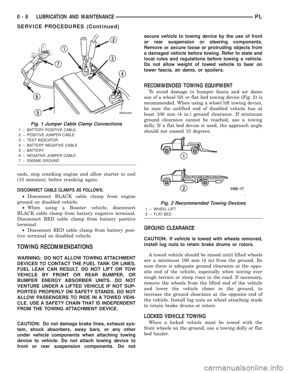
use of a wheel lift or flat bed towing device (Fig. 2) is
recommended. When using a wheel lift towing device,
be sure the unlifted end of disabled vehicle has at
least 100 mm (4 in.) ground clearance. If minimum
ground clearance cannot be reached, use a towing
dolly. If a flat bed device is used, the approach angle
should not exceed 15 degrees.
GROUND CLEARANCE
CAUTION: If vehicle is towed with wheels removed,
install lug nuts to retain brake drums or rotors.
A towed vehicle should be raised until lifted wheels
are a minimum 100 mm (4 in) from the ground. Be
sure there is adequate ground clearance at the oppo-
site end of the vehicle, especially when towing over
rough terrain or steep rises in the road. If necessary,
remove the wheels from the lifted end of the vehicle
and lower the vehicle closer to the ground, to
increase the ground clearance at the opposite end of
the vehicle. Install lug nuts on wheel attaching studs
to retain brake drums or rotors.
LOCKED VEHICLE TOWING
When a locked vehicle must be towed with the
front wheels on the ground, use a towing dolly or flat
bed hauler.
Fig. 1 Jumper Cable Clamp Connections
1 ± BATTERY POSITIVE CABLE
2 ± POSITIVE JUMPER CABLE
3 ± TEST INDICATOR
4 ± BATTERY NEGATIVE CABLE
5 ± BATTERY
6 ± NEGATIVE JUMPER CABLE
7 ± ENGINE GROUND
Fig. 2 Recommended Towing Devices
1 ± WHEEL LIFT
2 ± FLAT BED
0 - 8 LUBRICATION AND MAINTENANCEPL
SERVICE PROCEDURES (Continued)
Page 16 of 1285
SERVICE PROCEDURES
CURB HEIGHT MEASUREMENT
The wheel alignment is to be checked and all align-
ment adjustments made with the vehicle at its
required curb height specification.
Vehicle height is to be checked with the vehicle on
a flat, level surface, preferably a vehicle alignment
rack. The tires are to be inflated to the recommended
pressure. All tires are to be the same size as stan-
dard equipment. Vehicle height is checked with the
fuel tank full of fuel, and no passenger or luggage
compartment load.
Vehicle height is not adjustable. If the measure-
ment is not within specifications, inspect the vehicle
for bent or weak suspension components. Compare
the parts tag on the suspect coil spring(s) to the
parts book and the vehicle sales code, checking for a
match. Once removed from the vehicle, compare thecoil spring height to a correct new or known good coil
spring. The heights should vary if the suspect spring
is weak.
NOTE: Prior to reading the curb height measure-
ment, the front an rear of the vehicle should be
jounced. Induce jounce by grasping the center of
the rear, then front bumper (or fascia) and jouncing
the vehicle an equal number of times. Release the
bumper at the bottom of the jounce cycle.
(1) Measure from the inboard edge of the wheel
opening fender lip directly above the wheel center
(spindle), to the floor or alignment rack surface.
(2) When measuring, maximum left-to-right differ-
ential is not to exceed 10 mm (0.39 in.).
(3) Compare the measurements to specifications
listed in the following CURB HEIGHT SPECIFICA-
TIONS chart.
CURB HEIGHT SPECIFICATIONS
VEHICLE FRONT REAR
ALL NEON672 mm68 mm 679 mm68mm
26.46 in.60.32 in. 26.73 in.60.32 in.
WHEEL ALIGNMENT
PRE-WHEEL ALIGNMENT VEHICLE INSPECTION
CAUTION: If during the inspection the front sus-
pension crossmember shows any sign of impact
damage, the steering column lower coupling must
be inspected. Refer to DIAGNOSIS AND TESTING in
the STEERING group in this service manual.
Before any attempt is made to change or correct
the wheel alignment, the following inspection and
necessary corrections must be made to the vehicle to
ensure proper alignment.
(1) Be sure the fuel tank is full of fuel. If the fuel
tank is not full, the reduction in weight will affect
the curb height of the vehicle and the alignment
specifications.
(2) The passenger and luggage compartments of
the vehicle should be free of any load that is not fac-
tory equipment.
(3) Check the tires on the vehicle. The tires are to
be inflated to the recommended air pressure. All tires
must be the same size and in good condition with
approximately the same tread wear.
(4) Check the front tire and wheel assemblies for
excessive radial runout.(5) Inspect all suspension component fasteners for
looseness and torque.
(6) Inspect the lower front ball joints and all steer-
ing linkage for looseness and any sign of wear or
damage.
(7) Inspect the rubber bushings on all the suspen-
sion components for signs of wear or deterioration. If
any bushings show signs of wear or deterioration,
they should be replaced prior to aligning the vehicle.
WHEEL ALIGNMENT SETUP
(1) Position the vehicle on an alignment rack.
(2) Install all required alignment equipment on
the vehicle, per the alignment equipment manufac-
turer's instructions. On this vehicle, a four-wheel
alignment is recommended.
NOTE: Prior to reading the vehicle's alignment
readouts, the front and rear of vehicle should be
jounced. Induce jounce (rear first, then front) by
grasping the center of the bumper and jouncing
each end of vehicle an equal number of times. The
bumper should always be released when vehicle is
at the bottom of the jounce cycle.
(3) Read the vehicle's current front and rear align-
ment settings. Compare the vehicle's current align-
ment settings to the vehicle specifications for camber,
caster and toe-in. Refer to WHEEL ALIGNMENT
PLSUSPENSION 2 - 5
Page 17 of 1285
SPECIFICATIONS in this section of this service
manual group.
(4) If the rear alignment is out of specification,
adjust it first before proceeding to the front.
CAMBER AND CASTER
Front and rear camber and caster settings on this
vehicle are determined at the time the vehicle is
designed, by the location of the vehicle's suspension
components. This is referred to as Net Build. The
result is no required adjustment of camber and
caster after the vehicle is built or when servicing the
suspension components. Thus, when performing a
wheel alignment, caster and camber are not normally
considered adjustable angles. Camber and caster
should be checked to ensure they meet vehicle speci-
fications.
If either front or rear camber is found not to meet
alignment specifications, it can be adjusted using an
available camber adjustment bolt package. Before
installing a camber adjustment bolt package on a
vehicle found to be outside the specifications, inspect
the suspension components for any signs of damage
or bending.
No adjustment can be made to the caster setting
on this vehicle. If the vehicle's caster is not within
alignment specifications, check for damaged suspen-
sion components or body parts.
CAUTION: Do not attempt to adjust the vehicles
wheel alignment by heating or bending any of the
suspension components.
CAMBER ADJUSTMENT BOLT PACKAGE INSTALLATION
NOTE: The following procedure should only be
used on vehicles without the ACR competition
package.
The camber adjustment bolt package contains new
bolts and nuts for attaching the strut clevis bracket
to the steering knuckle. The bolts contained in the
package are slightly undersize allowing for move-
ment between the strut clevis bracket and the steer-
ing knuckle. The movement allowed by the undersize
bolts provide approximately two degrees of camber
adjustment per side of the vehicle. To install and
adjust the camber adjustment bolt package, follow
the procedure below.
CAUTION: There are separate camber adjustment
bolt packages for the front and rear of the vehicle.
Be sure to use the correct package.
(1) Raise the vehicle until its tires are not support-
ing the weight of the vehicle.CAUTION: The knuckle to strut assembly attaching
bolt shanks are serrated and must not be turned
during removal. Remove the nuts while holding the
bolts stationary.
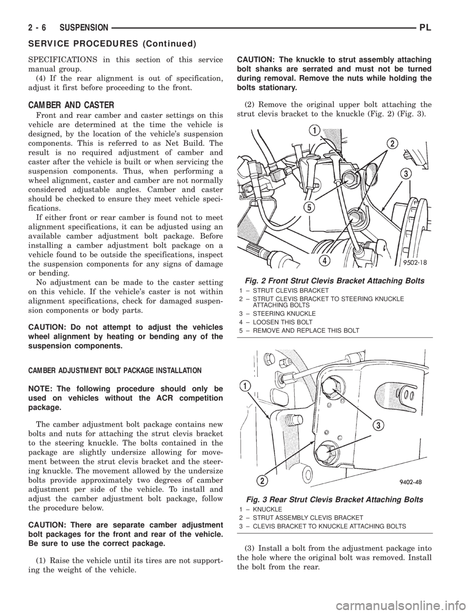
(2) Remove the original upper bolt attaching the
strut clevis bracket to the knuckle (Fig. 2) (Fig. 3).
(3) Install a bolt from the adjustment package into
the hole where the original bolt was removed. Install
the bolt from the rear.
Fig. 2 Front Strut Clevis Bracket Attaching Bolts
1 ± STRUT CLEVIS BRACKET
2 ± STRUT CLEVIS BRACKET TO STEERING KNUCKLE
ATTACHING BOLTS
3 ± STEERING KNUCKLE
4 ± LOOSEN THIS BOLT
5 ± REMOVE AND REPLACE THIS BOLT
Fig. 3 Rear Strut Clevis Bracket Attaching Bolts
1 ± KNUCKLE
2 ± STRUT ASSEMBLY CLEVIS BRACKET
3 ± CLEVIS BRACKET TO KNUCKLE ATTACHING BOLTS
2 - 6 SUSPENSIONPL
SERVICE PROCEDURES (Continued)
Page 24 of 1285
STEERING KNUCKLE
The front suspension steering knuckle is not a
repairable component of the front suspension. It
must be replaced if found to be damaged in any way.
If it is determined that the steering knuckle is bent
when servicing the vehicle, no attempt is to be made
to straighten the steering knuckle.
WHEEL BEARING AND HUB
The wheel bearing is designed for the life of the
vehicle and requires no type of periodic maintenance.
The following procedure may be used for diagnosing
the condition of the wheel bearing and hub.
With the wheel, disc brake caliper, and brake rotor
removed, rotate the wheel hub. Any roughness or
resistance to rotation may indicate dirt intrusion or a
failed hub bearing. If the bearing exhibits any of
these conditions during diagnosis, the hub bearing
will require replacement. The bearing is not service-
able.Damaged bearing seals and the resulting excessive
grease loss may also require bearing replacement.
Moderate grease weapage from the bearing is consid-
ered normal and should not require replacement of
the wheel bearing.
To diagnose a bent hub, refer to BRAKE ROTOR in
the DIAGNOSIS AND TESTING section in the
BRAKES service manual group for the procedure on
measuring hub runout.
LOWER CONTROL ARM
Inspect the lower control arm for signs of damage
from contact with the ground or road debris. If the
lower control arm shows any sign of damage, look for
distortion. Do not attempt to repair or straighten a
broken or bent lower control arm. If damaged, the
lower control arm stamping is serviced only as a
complete component.
The serviceable components of the lower control
arm are: the ball joint, the ball joint grease seal and
the lower control arm rear isolator bushing.
Inspect both lower control arm isolator bushings
for severe deterioration and replace as required.
Inspect the ball joint per the inspection procedure in
this section of the service manual and replace as
required. Refer to BALL JOINT in this section of this
service manual group.
BALL JOINT
With the weight of the vehicle resting on the road
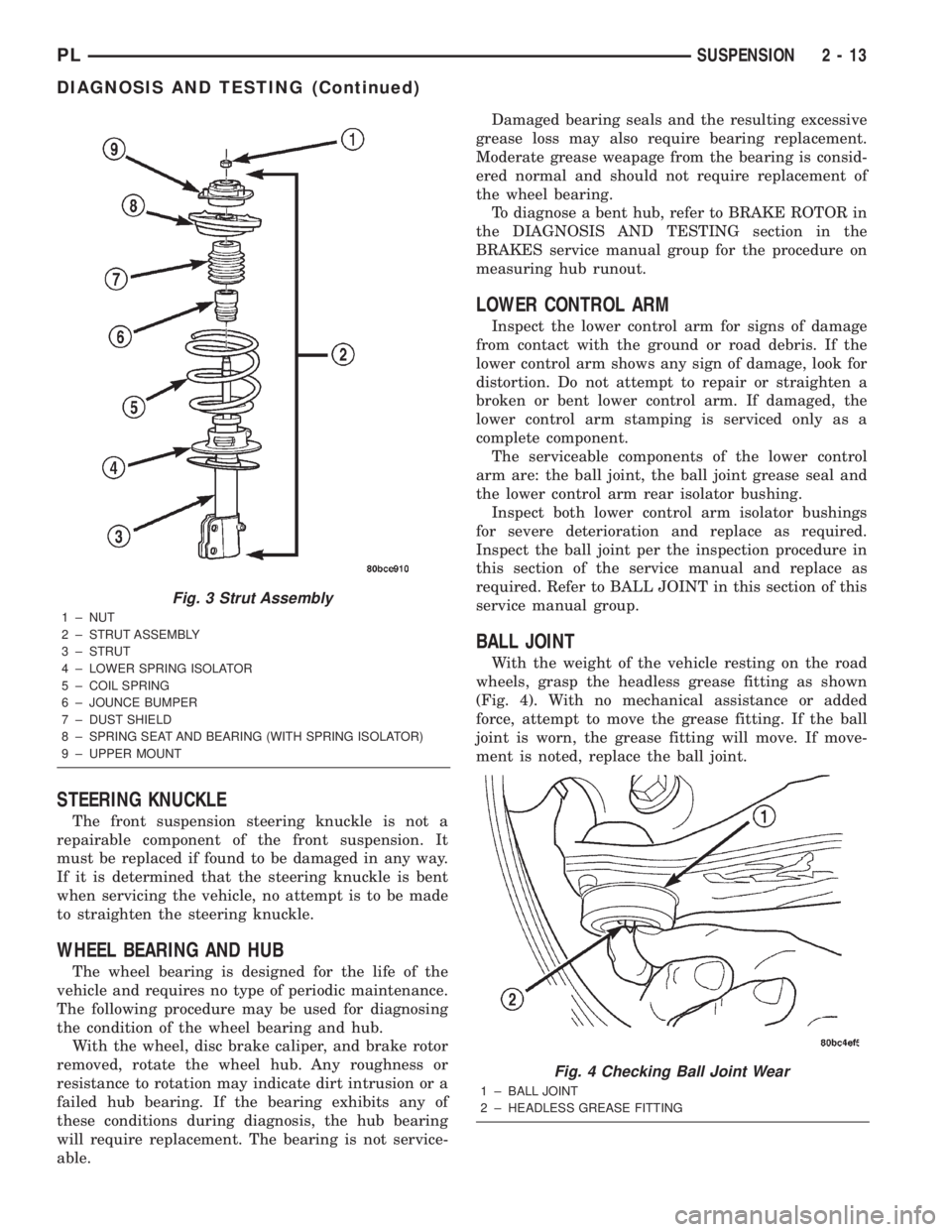
wheels, grasp the headless grease fitting as shown
(Fig. 4). With no mechanical assistance or added
force, attempt to move the grease fitting. If the ball
joint is worn, the grease fitting will move. If move-
ment is noted, replace the ball joint.
Fig. 3 Strut Assembly
1 ± NUT
2 ± STRUT ASSEMBLY
3 ± STRUT
4 ± LOWER SPRING ISOLATOR
5 ± COIL SPRING
6 ± JOUNCE BUMPER
7 ± DUST SHIELD
8 ± SPRING SEAT AND BEARING (WITH SPRING ISOLATOR)
9 ± UPPER MOUNT
Fig. 4 Checking Ball Joint Wear
1 ± BALL JOINT
2 ± HEADLESS GREASE FITTING
PLSUSPENSION 2 - 13
DIAGNOSIS AND TESTING (Continued)
Page 25 of 1285
CAUTION: No attempt should be made to service
the headless grease fitting on the ball joint. It has
been purposely snapped off by the manufacturer to
avoid over-greasing.
STABILIZER BAR (FRONT)
Inspect for broken, cracked or distorted stabilizer
bar cushions and retainers. Inspect for worn or dam-
aged stabilizer bar links (Fig. 1).
SERVICE PROCEDURES
LUBRICATION
There are no serviceable lubrication points on the
front suspension. The front lower ball joints have
grease fittings which have had the head snapped off
by the manufacturer after they have been filled. This
has been done to eliminate the possibility of damag-
ing the non-vented seals. Grease will not leak from
the broken grease fittings. The ball joints are sealed
for life and require no maintenance.
CAUTION: No attempt should be made to replace
the ball joint grease fitting with a new fitting, then
filling the ball joint with grease. Damage to the
grease seal can result.
REMOVAL AND INSTALLATION
SERVICE WARNINGS AND CAUTIONS
WARNING: DO NOT REMOVE THE STRUT SHAFT
NUT WHILE STRUT ASSEMBLY IS INSTALLED IN
VEHICLE, OR BEFORE THE COIL SPRING IS COM-
PRESSED WITH A COMPRESSION TOOL. THE
SPRING IS HELD UNDER HIGH PRESSURE.
CAUTION: Only frame contact hoisting equipment
can be used on this vehicle. All vehicles have a
fully independent rear suspension. The vehicles
cannot be hoisted using equipment designed to lift
a vehicle by the rear axle. If this type of hoisting
equipment is used, damage to rear suspension
components will occur.
CAUTION: At no time when servicing a vehicle can
a sheet metal screw, bolt, or other metal fastener be
installed in the shock tower to take the place of an
original plastic clip. It may come into contact with
the strut or coil spring.CAUTION: Wheel bearing damage will result if after
loosening the hub nut, the vehicle is rolled on the
ground or the weight of the vehicle is allowed to be
supported by the tires for a length of time.
STRUT ASSEMBLY (FRONT)
NOTE: Before proceeding with this procedure,
review SERVICE WARNINGS AND CAUTIONS at the
beginning of REMOVAL AND INSTALLATION in this
section.
REMOVAL
(1) Raise the vehicle. Refer to HOISTING in the
LUBRICATION AND MAINTENANCE group for the
proper lifting procedure.
(2) Remove tire and wheel assembly from location
on front of vehicle requiring strut removal.
(3) If both strut assemblies are to be removed,
mark the strut assemblies right or left according to
which side of the vehicle they were removed from.
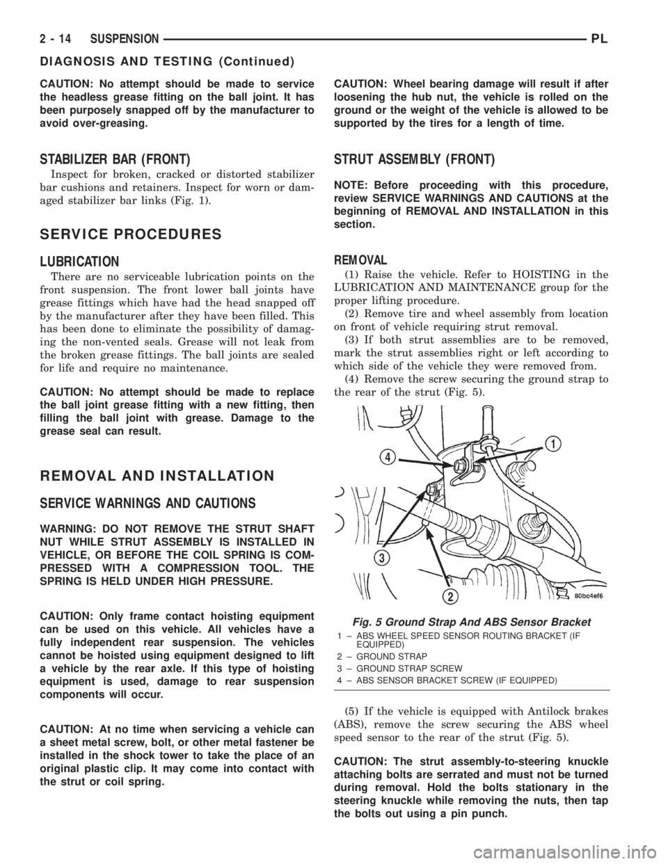
(4) Remove the screw securing the ground strap to
the rear of the strut (Fig. 5).
(5) If the vehicle is equipped with Antilock brakes
(ABS), remove the screw securing the ABS wheel
speed sensor to the rear of the strut (Fig. 5).
CAUTION: The strut assembly-to-steering knuckle
attaching bolts are serrated and must not be turned
during removal. Hold the bolts stationary in the
steering knuckle while removing the nuts, then tap
the bolts out using a pin punch.
Fig. 5 Ground Strap And ABS Sensor Bracket
1 ± ABS WHEEL SPEED SENSOR ROUTING BRACKET (IF
EQUIPPED)
2 ± GROUND STRAP
3 ± GROUND STRAP SCREW
4 ± ABS SENSOR BRACKET SCREW (IF EQUIPPED)
2 - 14 SUSPENSIONPL
DIAGNOSIS AND TESTING (Continued)
Page 48 of 1285
For more information on the description and oper-
ation of an individual component, refer to the appli-
cable component heading in this section.
STRUT ASSEMBLY (REAR)
The rear strut assemblies support the weight of
the vehicle using coil springs positioned around
struts. The coil springs are contained between the
upper mount of the strut assembly and a lower
spring seat on the body of the strut.
The top of each strut assembly is bolted to the top
of the inner fender through a rubber isolated mount.
The bottom of the strut assembly attaches to the rear
knuckle using 2 thru-bolts with prevailing torque
nuts.
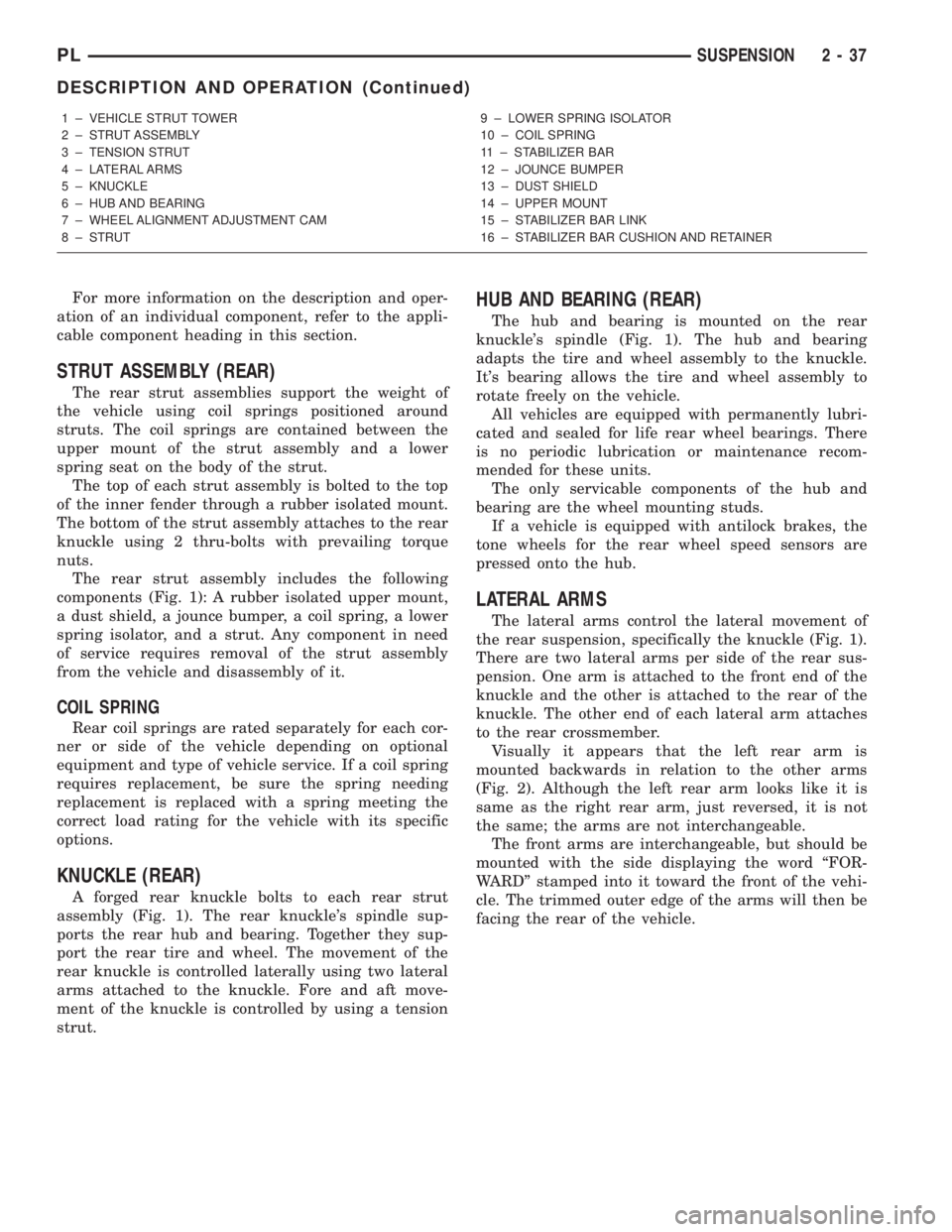
The rear strut assembly includes the following
components (Fig. 1): A rubber isolated upper mount,
a dust shield, a jounce bumper, a coil spring, a lower
spring isolator, and a strut. Any component in need
of service requires removal of the strut assembly
from the vehicle and disassembly of it.
COIL SPRING
Rear coil springs are rated separately for each cor-
ner or side of the vehicle depending on optional
equipment and type of vehicle service. If a coil spring
requires replacement, be sure the spring needing
replacement is replaced with a spring meeting the
correct load rating for the vehicle with its specific
options.
KNUCKLE (REAR)
A forged rear knuckle bolts to each rear strut
assembly (Fig. 1). The rear knuckle's spindle sup-
ports the rear hub and bearing. Together they sup-
port the rear tire and wheel. The movement of the
rear knuckle is controlled laterally using two lateral
arms attached to the knuckle. Fore and aft move-
ment of the knuckle is controlled by using a tension
strut.
HUB AND BEARING (REAR)
The hub and bearing is mounted on the rear
knuckle's spindle (Fig. 1). The hub and bearing
adapts the tire and wheel assembly to the knuckle.
It's bearing allows the tire and wheel assembly to
rotate freely on the vehicle.
All vehicles are equipped with permanently lubri-
cated and sealed for life rear wheel bearings. There
is no periodic lubrication or maintenance recom-
mended for these units.
The only servicable components of the hub and
bearing are the wheel mounting studs.
If a vehicle is equipped with antilock brakes, the
tone wheels for the rear wheel speed sensors are
pressed onto the hub.
LATERAL ARMS
The lateral arms control the lateral movement of
the rear suspension, specifically the knuckle (Fig. 1).
There are two lateral arms per side of the rear sus-
pension. One arm is attached to the front end of the
knuckle and the other is attached to the rear of the
knuckle. The other end of each lateral arm attaches
to the rear crossmember.
Visually it appears that the left rear arm is
mounted backwards in relation to the other arms
(Fig. 2). Although the left rear arm looks like it is
same as the right rear arm, just reversed, it is not
the same; the arms are not interchangeable.
The front arms are interchangeable, but should be
mounted with the side displaying the word ªFOR-
WARDº stamped into it toward the front of the vehi-
cle. The trimmed outer edge of the arms will then be
facing the rear of the vehicle.
1 ± VEHICLE STRUT TOWER
2 ± STRUT ASSEMBLY
3 ± TENSION STRUT
4 ± LATERAL ARMS
5 ± KNUCKLE
6 ± HUB AND BEARING
7 ± WHEEL ALIGNMENT ADJUSTMENT CAM
8 ± STRUT9 ± LOWER SPRING ISOLATOR
10 ± COIL SPRING
11 ± STABILIZER BAR
12 ± JOUNCE BUMPER
13 ± DUST SHIELD
14 ± UPPER MOUNT
15 ± STABILIZER BAR LINK
16 ± STABILIZER BAR CUSHION AND RETAINER
PLSUSPENSION 2 - 37
DESCRIPTION AND OPERATION (Continued)
Page 62 of 1285
DIFFERENTIAL AND DRIVELINE
TABLE OF CONTENTS
page page
DESCRIPTION AND OPERATION
FRONT DRIVESHAFTS.....................1
DIAGNOSIS AND TESTING
DRIVESHAFT DIAGNOSIS...................2
REMOVAL AND INSTALLATION
DRIVESHAFTS...........................3
DISASSEMBLY AND ASSEMBLY
DRIVESHAFT RECONDITION................7INNER TRIPOD JOINT SEAL BOOT...........7
OUTER C/V JOINT SEAL BOOT.............13
SPECIFICATIONS
TORQUE...............................17
SPECIAL TOOLS
DRIVESHAFT............................17
DESCRIPTION AND OPERATION
FRONT DRIVESHAFTS
Vehicles equipped with either an automatic or
manual transmission use an unequal±length drive-
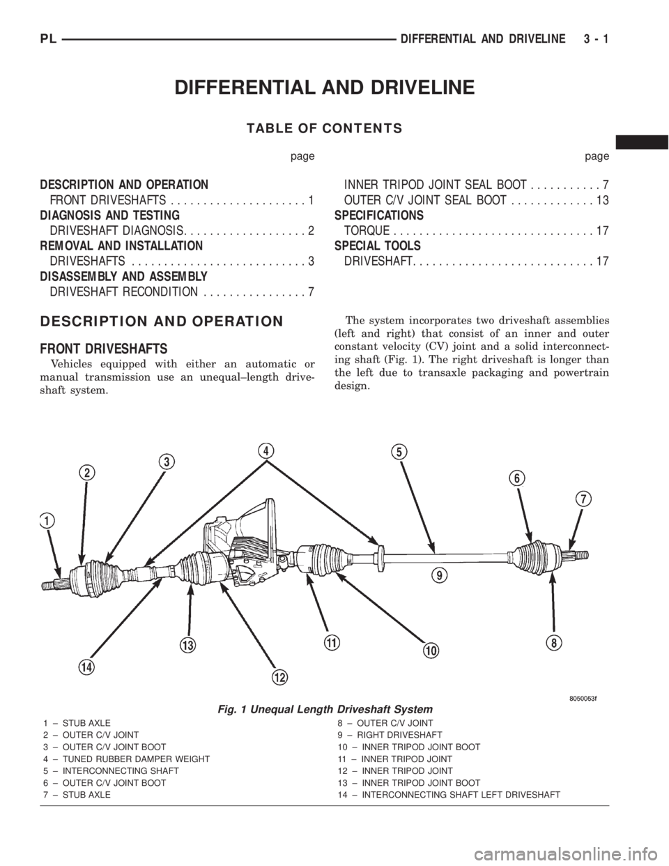
shaft system.The system incorporates two driveshaft assemblies
(left and right) that consist of an inner and outer
constant velocity (CV) joint and a solid interconnect-
ing shaft (Fig. 1). The right driveshaft is longer than
the left due to transaxle packaging and powertrain
design.
Fig. 1 Unequal Length Driveshaft System
1 ± STUB AXLE
2 ± OUTER C/V JOINT
3 ± OUTER C/V JOINT BOOT
4 ± TUNED RUBBER DAMPER WEIGHT
5 ± INTERCONNECTING SHAFT
6 ± OUTER C/V JOINT BOOT
7 ± STUB AXLE8 ± OUTER C/V JOINT
9 ± RIGHT DRIVESHAFT
10 ± INNER TRIPOD JOINT BOOT
11 ± INNER TRIPOD JOINT
12 ± INNER TRIPOD JOINT
13 ± INNER TRIPOD JOINT BOOT
14 ± INTERCONNECTING SHAFT LEFT DRIVESHAFT
PLDIFFERENTIAL AND DRIVELINE 3 - 1
Page 63 of 1285
Driveshafts used on both the right and left sides of
the vehicle use a tuned rubber damper weight
mounted to the interconnecting shaft (Fig. 1). The
damper weight applications vary by which side of the
vehicle the driveshaft is located on and the transmis-
sion application of the vehicle. When replacing a
driveshaft, be sure the replacement driveshaft has
the same damper weight as the original.
Both driveshaft assemblies use the same type of
inner and outer joints. The inner joint of both drive-
shaft assemblies is a tripod joint, and the outer joint
of both driveshaft assemblies is a Rzeppa joint. Both
tripod joints and Rzeppa joints are true constant
velocity (C/V) joint assemblies. The inner tripod joint
allows for the changes in driveshaft length through
the jounce and rebound travel of the front suspen-
sion.
On vehicles equipped with ABS brakes, the outer
C/V joint is equipped with a tone wheel used to
determine vehicle speed for ABS brake operation.
The inner tripod joint of both driveshafts is splined
into the transaxle side gears. The inner tripod joints
are retained in the side gears of the transaxle using
a snap ring located in the stub shaft of the tripod
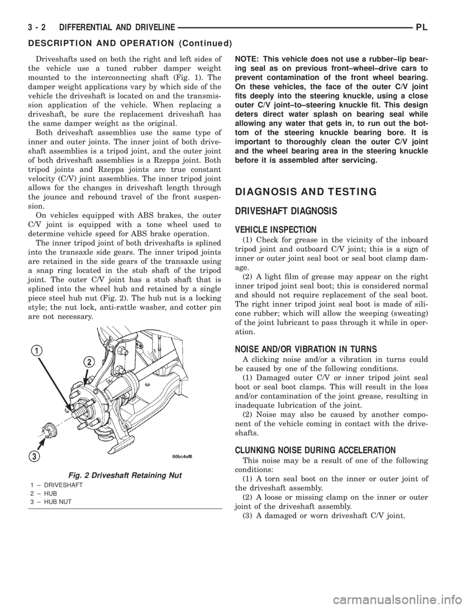
joint. The outer C/V joint has a stub shaft that is
splined into the wheel hub and retained by a single
piece steel hub nut (Fig. 2). The hub nut is a locking
style; the nut lock, anti-rattle washer, and cotter pin
are not necessary.NOTE: This vehicle does not use a rubber±lip bear-
ing seal as on previous front±wheel±drive cars to
prevent contamination of the front wheel bearing.
On these vehicles, the face of the outer C/V joint
fits deeply into the steering knuckle, using a close
outer C/V joint±to±steering knuckle fit. This design
deters direct water splash on bearing seal while
allowing any water that gets in, to run out the bot-
tom of the steering knuckle bearing bore. It is
important to thoroughly clean the outer C/V joint
and the wheel bearing area in the steering knuckle
before it is assembled after servicing.
DIAGNOSIS AND TESTING
DRIVESHAFT DIAGNOSIS
VEHICLE INSPECTION
(1) Check for grease in the vicinity of the inboard
tripod joint and outboard C/V joint; this is a sign of
inner or outer joint seal boot or seal boot clamp dam-
age.
(2) A light film of grease may appear on the right
inner tripod joint seal boot; this is considered normal
and should not require replacement of the seal boot.
The right inner tripod joint seal boot is made of sili-
cone rubber; which will allow the weeping (sweating)
of the joint lubricant to pass through it while in oper-
ation.
NOISE AND/OR VIBRATION IN TURNS
A clicking noise and/or a vibration in turns could
be caused by one of the following conditions.
(1) Damaged outer C/V or inner tripod joint seal
boot or seal boot clamps. This will result in the loss
and/or contamination of the joint grease, resulting in
inadequate lubrication of the joint.
(2) Noise may also be caused by another compo-
nent of the vehicle coming in contact with the drive-
shafts.
CLUNKING NOISE DURING ACCELERATION
This noise may be a result of one of the following
conditions:
(1) A torn seal boot on the inner or outer joint of
the driveshaft assembly.
(2) A loose or missing clamp on the inner or outer
joint of the driveshaft assembly.
(3) A damaged or worn driveshaft C/V joint.
Fig. 2 Driveshaft Retaining Nut
1 ± DRIVESHAFT
2 ± HUB
3 ± HUB NUT
3 - 2 DIFFERENTIAL AND DRIVELINEPL
DESCRIPTION AND OPERATION (Continued)