2000 DODGE NEON weight
[x] Cancel search: weightPage 114 of 1285
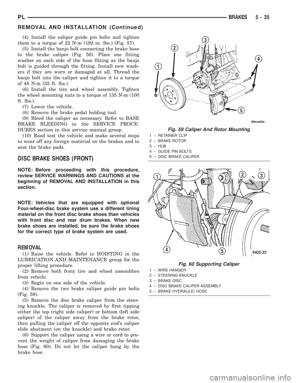
(4) Install the caliper guide pin bolts and tighten
them to a torque of 22 N´m (192 in. lbs.) (Fig. 57).
(5) Install the banjo bolt connecting the brake hose
to the brake caliper (Fig. 56). Place one fitting
washer on each side of the hose fitting as the banjo
bolt is guided through the fitting. Install new wash-
ers if they are worn or damaged at all. Thread the
banjo bolt into the caliper and tighten it to a torque
of 48 N´m (35 ft. lbs.).
(6) Install the tire and wheel assembly. Tighten
the wheel mounting nuts to a torque of 135 N´m (100
ft. lbs.).
(7) Lower the vehicle.
(8) Remove the brake pedal holding tool.
(9) Bleed the caliper as necessary. Refer to BASE
BRAKE BLEEDING in the SERVICE PROCE-
DURES section in this service manual group.
(10) Road test the vehicle and make several stops
to wear off any foreign material on the brakes and to
seat the brake pads.
DISC BRAKE SHOES (FRONT)
NOTE: Before proceeding with this procedure,
review SERVICE WARNINGS AND CAUTIONS at the
beginning of REMOVAL AND INSTALLATION in this
section.
NOTE: Vehicles that are equipped with optional
Four-wheel-disc brake system use a different lining
material on the front disc brake shoes than vehicles
with front disc and rear drum brakes. When new
brake shoes are installed, be sure the brake shoes
for the correct type of brake system are used.
REMOVAL
(1) Raise the vehicle. Refer to HOISTING in the
LUBRICATION AND MAINTENANCE group for the
proper lifting procedure.
(2) Remove both front tire and wheel assemblies
from vehicle.
(3) Begin on one side of the vehicle.
(4) Remove the two brake caliper guide pin bolts
(Fig. 59).
(5) Remove the disc brake caliper from the steer-
ing knuckle. The caliper is removed by first tipping
either the top (right side caliper) or bottom (left side
caliper) of the caliper away from the brake rotor,
then pulling the caliper off the opposite end's caliper
slide abutment (on the knuckle) and brake rotor.
(6) Support the caliper using a wire or cord to pre-
vent the weight of caliper from damaging the brake
hose (Fig. 60). Do not let the caliper hang by the
brake hose.
Fig. 59 Caliper And Rotor Mounting
1 ± RETAINER CLIP
2 ± BRAKE ROTOR
3 ± HUB
4 ± GUIDE PIN BOLTS
5 ± DISC BRAKE CALIPER
Fig. 60 Supporting Caliper
1 ± WIRE HANGER
2 ± STEERING KNUCKLE
3 ± BRAKE DISC
4 ± DISC BRAKE CALIPER ASSEMBLY
5 ± BRAKE HYDRAULIC HOSE
PLBRAKES 5 - 35
REMOVAL AND INSTALLATION (Continued)
Page 119 of 1285
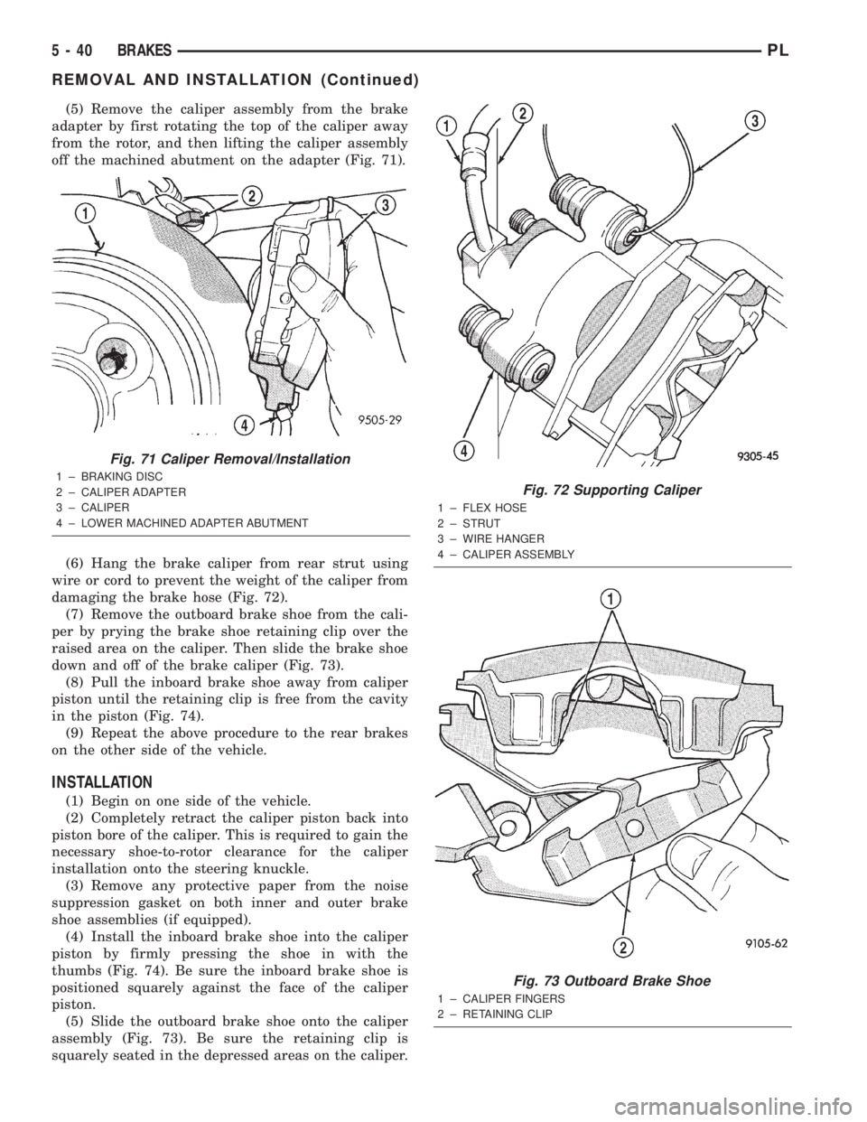
(5) Remove the caliper assembly from the brake
adapter by first rotating the top of the caliper away
from the rotor, and then lifting the caliper assembly
off the machined abutment on the adapter (Fig. 71).
(6) Hang the brake caliper from rear strut using
wire or cord to prevent the weight of the caliper from
damaging the brake hose (Fig. 72).
(7) Remove the outboard brake shoe from the cali-
per by prying the brake shoe retaining clip over the
raised area on the caliper. Then slide the brake shoe
down and off of the brake caliper (Fig. 73).
(8) Pull the inboard brake shoe away from caliper
piston until the retaining clip is free from the cavity
in the piston (Fig. 74).
(9) Repeat the above procedure to the rear brakes
on the other side of the vehicle.
INSTALLATION
(1) Begin on one side of the vehicle.
(2) Completely retract the caliper piston back into
piston bore of the caliper. This is required to gain the
necessary shoe-to-rotor clearance for the caliper
installation onto the steering knuckle.
(3) Remove any protective paper from the noise
suppression gasket on both inner and outer brake
shoe assemblies (if equipped).
(4) Install the inboard brake shoe into the caliper
piston by firmly pressing the shoe in with the
thumbs (Fig. 74). Be sure the inboard brake shoe is
positioned squarely against the face of the caliper
piston.
(5) Slide the outboard brake shoe onto the caliper
assembly (Fig. 73). Be sure the retaining clip is
squarely seated in the depressed areas on the caliper.
Fig. 71 Caliper Removal/Installation
1 ± BRAKING DISC
2 ± CALIPER ADAPTER
3 ± CALIPER
4 ± LOWER MACHINED ADAPTER ABUTMENT
Fig. 72 Supporting Caliper
1 ± FLEX HOSE
2 ± STRUT
3 ± WIRE HANGER
4 ± CALIPER ASSEMBLY
Fig. 73 Outboard Brake Shoe
1 ± CALIPER FINGERS
2 ± RETAINING CLIP
5 - 40 BRAKESPL
REMOVAL AND INSTALLATION (Continued)
Page 238 of 1285
OPERATION
The Automatic Shutdown (ASD) relay supplies bat-
tery voltage to the fuel injectors, electronic ignition
coil and the heating elements in the oxygen sensors.
A buss bar in the Power Distribution Center (PDC)
supplies voltage to the solenoid side and contact side
of the relay. The fuse also protects the power circuit
for the fuel pump relay and pump. The fuse is
located in the PDC. Refer to the Wiring Diagrams for
circuit information.
The PCM controls the ASD relay by switching the
ground path for the solenoid side of the relay on and
off. The PCM turns the ground path off when the
ignition switch is in the Off position. When the igni-
tion switch is in On or Start, the PCM monitors the
crankshaft and camshaft position sensor signals to
determine engine speed and ignition timing (coil
dwell). If the PCM does not receive crankshaft and
camshaft position sensor signals when the ignition
switch is in the Run position, it will de-energize the
ASD relay.
CRANKSHAFT POSITION SENSORÐPCM
INPUT
DESCRIPTION
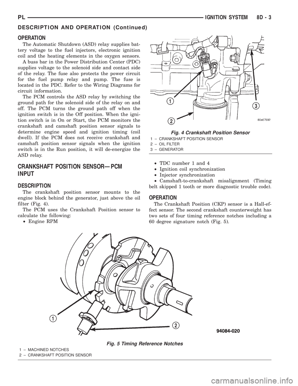
The crankshaft position sensor mounts to the
engine block behind the generator, just above the oil
filter (Fig. 4).
The PCM uses the Crankshaft Position sensor to
calculate the following:
²Engine RPM²TDC number 1 and 4
²Ignition coil synchronization
²Injector synchronization
²Camshaft-to-crankshaft misalignment (Timing
belt skipped 1 tooth or more diagnostic trouble code).
OPERATION
The Crankshaft Position (CKP) sensor is a Hall-ef-
fect sensor. The second crankshaft counterweight has
two sets of four timing reference notches including a
60 degree signature notch (Fig. 5).
Fig. 5 Timing Reference Notches
1 ± MACHINED NOTCHES
2 ± CRANKSHAFT POSITION SENSOR
Fig. 4 Crankshaft Position Sensor
1 ± CRANKSHAFT POSITION SENSOR
2 ± OIL FILTER
3 ± GENERATOR
PLIGNITION SYSTEM 8D - 3
DESCRIPTION AND OPERATION (Continued)
Page 239 of 1285
The PCM sends approximately 8 volts to the Hall-
effect sensor. This voltage is required to operate the
Hall-effect chip and the electronics inside the sensor.
A ground for the sensor is provided through the sen-
sor return circuit. The input to the PCM occurs on a
5 volt output reference circuit.
The notches generate pulses from high to low in
the crankshaft position sensor output voltage. When
a metal portion of the counterweight aligns with the
crankshaft position sensor, the sensor output voltage
goes low (less than 0.5 volts). When a notch aligns
with the sensor, voltage goes high (5.0 volts). As a
group of notches pass under the sensor, the output
voltage switches from low (metal) to high (notch)
then back to low.
If available, an oscilloscope can display the square
wave patterns of each voltage pulses. From the width
of the output voltage pulses, the PCM calculates
engine speed. The width of the pulses represent the
amount of time the output voltage stays high before
switching back to low. The period of time the sensor
output voltage stays high before switching back to
low is referred to as pulse width. The faster the
engine is operating, the smaller the pulse width on
the oscilloscope.
By counting the pulses and referencing the pulse
from the 60 degree signature notch, the PCM calcu-
lates crankshaft angle (position). In each group of
timing reference notches, the first notch represents
69 degrees before top dead center (BTDC). The sec-
ond notch represents 49 degrees BTDC. The third
notch represents 29 degrees. The last notch in each
set represents 9 degrees before top dead center
(TDC).
The timing reference notches are machined at 20É
increments. From the voltage pulse width the PCM
tells the difference between the timing reference
notches and the 60 degree signature notch. The 60
degree signature notch produces a longer pulse width
than the smaller timing reference notches. If the
camshaft position sensor input switches from high to
low when the 60 degree signature notch passes under
the crankshaft position sensor, the PCM knows cylin-
der number one is the next cylinder at TDC.CAMSHAFT POSITION SENSORÐPCM INPUT
DESCRIPTION
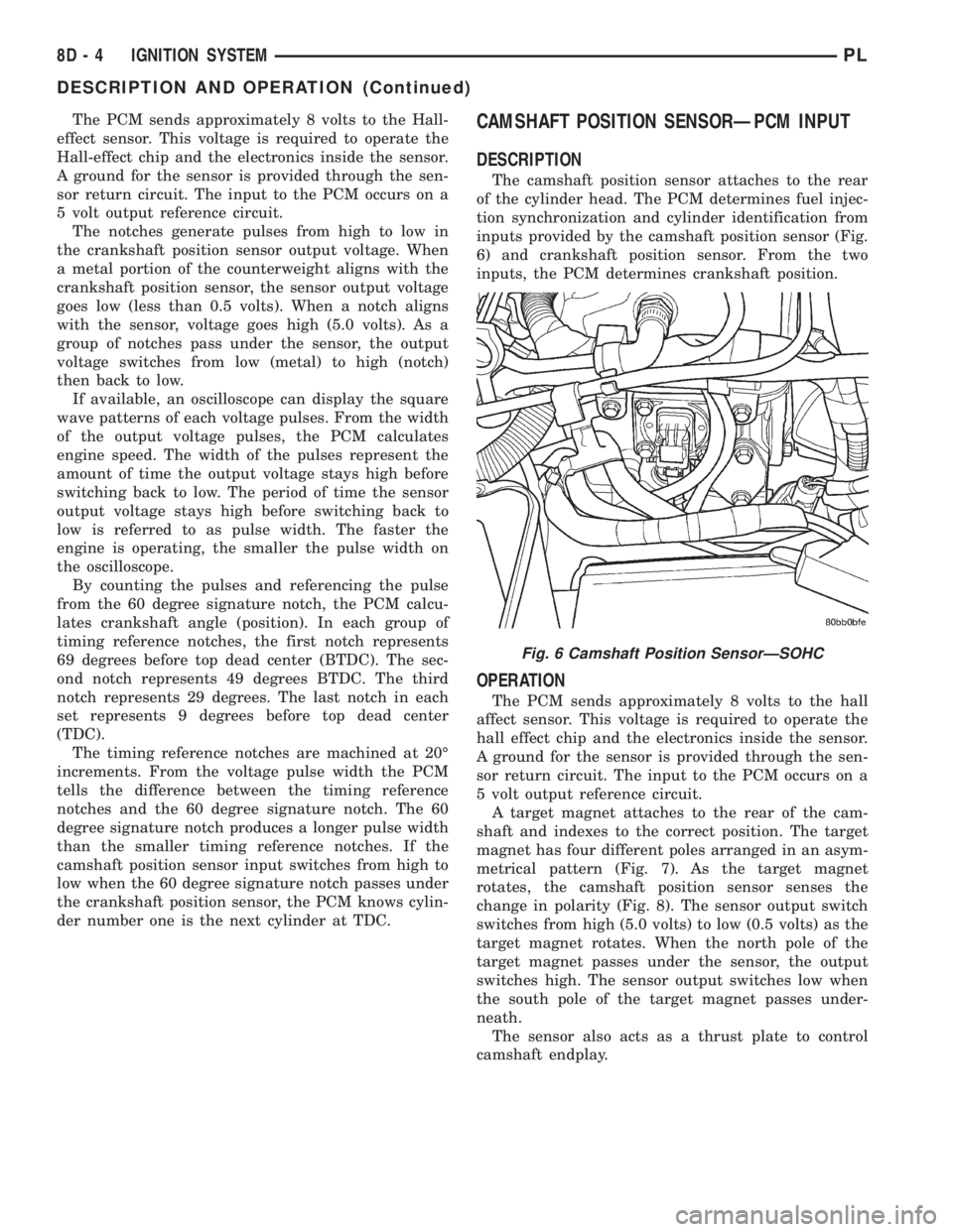
The camshaft position sensor attaches to the rear
of the cylinder head. The PCM determines fuel injec-
tion synchronization and cylinder identification from
inputs provided by the camshaft position sensor (Fig.
6) and crankshaft position sensor. From the two
inputs, the PCM determines crankshaft position.
OPERATION
The PCM sends approximately 8 volts to the hall
affect sensor. This voltage is required to operate the
hall effect chip and the electronics inside the sensor.
A ground for the sensor is provided through the sen-
sor return circuit. The input to the PCM occurs on a
5 volt output reference circuit.
A target magnet attaches to the rear of the cam-
shaft and indexes to the correct position. The target
magnet has four different poles arranged in an asym-
metrical pattern (Fig. 7). As the target magnet
rotates, the camshaft position sensor senses the
change in polarity (Fig. 8). The sensor output switch
switches from high (5.0 volts) to low (0.5 volts) as the
target magnet rotates. When the north pole of the
target magnet passes under the sensor, the output
switches high. The sensor output switches low when
the south pole of the target magnet passes under-
neath.
The sensor also acts as a thrust plate to control
camshaft endplay.
Fig. 6 Camshaft Position SensorÐSOHC
8D - 4 IGNITION SYSTEMPL
DESCRIPTION AND OPERATION (Continued)
Page 311 of 1285
HEADLAMP ALIGNMENT
TABLE OF CONTENTS
page page
DESCRIPTION AND OPERATION
HEADLAMP ALIGNMENT....................4
SERVICE PROCEDURES
HEADLAMP ALIGNMENT PREPARATION........4ADJUSTMENTS
HEADLAMP ADJUSTMENT USING
ALIGNMENT SCREEN....................4
FOG LAMP ALIGNMENT....................6
DESCRIPTION AND OPERATION
HEADLAMP ALIGNMENT
Headlamps and Fog Lamps should be aligned
using the screen method which is provided in this
section.The preferred headlamp alignment set-
ting is 0 for the left/right adjustment and 0 for
the up/down adjustment.
SERVICE PROCEDURES
HEADLAMP ALIGNMENT PREPARATION
(1) Verify headlamp dimmer switch and high beam
indicator operation.
(2) Inspect and correct damaged or defective com-
ponents that could interfere with proper headlamp
alignment.
(3) Verify proper tire inflation.
(4) Clean headlamp lenses.
(5) Verify that luggage area is not heavily loaded.
(6) Fuel tank should be FULL. Add 2.94 kg (6.5
lbs.) of weight over the fuel tank for each estimated
gallon of missing fuel.
ADJUSTMENTS
HEADLAMP ADJUSTMENT USING ALIGNMENT
SCREEN
ALIGNMENT SCREEN PREPARATION
(1) Position vehicle on a level surface perpendicu-
lar to a flat wall 7.62 meters (25 ft.) away from front
of headlamp lens.
(2) If necessary, tape a line on the floor 7.62
meters (25 ft.) away from and parallel to the wall
(Fig. 1).(3) From the floor up 1.27 meters (5 ft.), tape a
line on the wall at the center line of the vehicle.
Sight along the center line of the vehicle (from rear
of vehicle forward) to verify accuracy of the line
placement.
(4) Rock vehicle side-to-side three times to allow
suspension to stabilize.
(5) Jounce front suspension three times by pushing
downward on front bumper and releasing.
(6) A small dot is molded into each headlamp lens
signifying the center of the headlamp. Measure the
distance from the center of the headlamp to the floor.
Transfer measurement to the alignment screen (with
tape). Use this line for up/down adjustment refer-
ence.
(7) Measure distance from the center line of the
vehicle to the center of each headlamp being aligned.
Transfer measurements to screen (with tape) to each
side of vehicle center line. Use these lines for left/
right adjustment reference.
HEADLAMP ADJUSTMENT
The PL headlamp low beam pattern has a distinct
horizontal cutoff line which is used to visually align
the headlamps. A properly aimed headlamp will have
the horizontal cutoff line of the low beam pattern
centered on the low beam pattern centered on the
horizontal center of headlamp line. The side to side
left edge of the low beam hot spot should be located
75 mm (3 inches) to the left of the headlamp center
line (Fig. 1). The high beams on a vehicle with aero
headlamps cannot be aligned. The high beam pattern
should be correct when the low beams are aligned
properly.
To adjust headlamp alignment, rotate alignment
screws to achieve the specified low beam hot spot
pattern.
8L - 4 LAMPSPL
Page 327 of 1285
HEADLAMP ALIGNMENT
TABLE OF CONTENTS
page page
DESCRIPTION AND OPERATION
HEADLAMP ALIGNMENT....................2
SERVICE PROCEDURES
HEADLAMP ALIGNMENT PREPARATION........2ADJUSTMENTS
HEADLAMP ADJUSTMENT USING
ALIGNMENT SCREEN....................2
DESCRIPTION AND OPERATION
HEADLAMP ALIGNMENT
Headlamps can be aligned using the screen method
provided in this section. This method will require the
vehicle to be parked on a flat, level surface with a
minimum of 15 meters of working room in front of a
flat, level perpendicular wall or aiming.
Each headlamp has a focal point circle molded on
the lens directly in front of each headlamp bulb.
These focal point circles are used to set up lines on a
wall, or aiming board for visually aiming the head-
lamps.
The driving (high) beam location does not require
adjustment. It will be correct when the passing (low)
beam headlamps are aimed correctly.
SERVICE PROCEDURES
HEADLAMP ALIGNMENT PREPARATION
(1) Verify headlamp dimmer switch and high beam
indicator operation.
(2) Inspect and correct damaged or defective com-
ponents that could interfere with proper headlamp
alignment.
(3) Verify that the headlamp leveling switch is in
the ª0º position.
(4) Verify proper tire inflation.
(5) Clean the headlamp lenses.
(6) Verify that the luggage area is not heavily
loaded.
(7) Fuel tank should be FULL. Add 2.94 kg (6.5
lbs.) of weight over the fuel tank for each estimated
gallon of missing fuel.
ADJUSTMENTS
HEADLAMP ADJUSTMENT USING ALIGNMENT
SCREEN
ALIGNMENT SCREEN PREPARATION
(1) Position the vehicle on a level surface 10
meters in front of a level, flat wall or aiming board.
(2) Tape a vertical line on the wall extending 1
meter up from the floor, making sure this line is even
with the centerline of the vehicle (Fig. 1).
(3) Measure the cross-car distance between the
two headlamp focal point circles (1174mm). Transfer
half of this distance (587mm) to the left of the vehicle
centerline and tape another vertical line up from the
floor 1 meter (Fig. 1). Repeat for the right side of the
centerline.
(4) Measure the distance from the floor to the focal
point circle on the headlamp lens (635mm, but may
vary due to variations in tire size and vehicle suspen-
sion height). Transfer this measurement to the wall
and tape a horizontal line extending approximately 1
meter beyond each vertical focal point line (Fig. 1).
(5) Use these lines for left and right adjustment
reference.
HEADLAMP ADJUSTMENT
Horizontal Adjustment
The horizontal position of the passing (low) beam
pattern is adjusted by turning the T-15 Torx screw.
Located through the slot in the upper-crossmember
between the two attaching straps of the headlamp.
Vertical Adjustment
The vertical position of the passing (low) beam pat-
tern is adjusted by turning the Phillips screw on top
of the headlamp leveling motor. Located between the
headlamp housing and the upper-crossmember, just
inboard of the fender.
Adjust the passing (low) beam headlamp pat-
terns to the locations shown in the chart pro-
vided (Fig. 1).
8L - 2 LAMPSPL
Page 727 of 1285
will clean up a bore and maintain the required lim-
its.
(2) Deglazing of the cylinder walls may be done
using a cylinder surfacing hone, recommended tool
C-3501 or equivalent, equipped with 280 grit stones,
if the cylinder bore is straight and round. 20±60
strokes depending on the bore condition, will be suf-
ficient to provide a satisfactory surface. Inspect cyl-
inder walls after each 20 strokes, using a light
honing oil.Do not use engine or transmission oil,
mineral spirits or kerosene.
(3) Honing should be done by moving the hone up
and down fast enough to get a cross-hatch pattern.
When hone marksintersectat 50-60 degrees, the
cross hatch angle is most satisfactory for proper seat-
ing of rings (Fig. 4).
(4) A controlled hone motor speed between
200±300 RPM is necessary to obtain the proper cross-
hatch angle. The number of up and down strokes per
minute can be regulated to get the desired 50±60
degree angle. Faster up and down strokes increase
the cross-hatch angle.
(5) After honing, it is necessary that the block be
cleaned again to remove all traces of abrasive.
CAUTION: Ensure all abrasives are removed from
engine parts after honing. It is recommended that a
solution of soap and hot water be used with a
brush and the parts then thoroughly dried. The bore
can be considered clean when it can be wiped
clean with a white cloth and cloth remains clean.
Oil the bores after cleaning to prevent rusting.MEASURING WITH PLASTIGAGE
PLASTIGAGE METHOD
Engine crankshaft bearing clearances can be deter-
mined by use of Plastigage or equivalent. The follow-
ing is the recommended procedure for the use of
Plastigage:
NOTE: The total clearance of the main bearings can
only be determined by removing the weight of the
crankshaft. This can be accomplished by either of
two methods:
PREFERRED METHOD
Shim the bearings adjacent to the bearing to be
checked in order to remove the clearance between
upper bearing shell and the crankshaft. This can be
accomplished by placing a minimum of 0.254 mm
(0.010 in.) shim (e. g. cardboard, matchbook cover,
etc.) between the bearing shell and the bearing cap
on the adjacent bearings and tightening bolts to
14-20 N´m (10-15 ft. lbs.). The number of main bear-
ing will vary from engine to engine.
ENGINE WITH 5 MAIN BEARINGS
²When checking #1 main bearing shim #2 main
bearing.
²When checking #2 main bearing shim #1 & 3
main bearing.
²When checking #3 main bearing shim #2 & 4
main bearing.
²When checking #4 main bearing shim #3 & 5
main bearing.
²When checking #5 main bearing shim #4 main
bearing.
ENGINE WITH 4 MAIN BEARING
²When checking #1 main bearing shim # 2 main
bearing.
Fig. 4 Cylinder Bore Cross-Hatch Pattern
1 ± CROSS-HATCH PATTERN
Fig. 5 Plastigage Placed in Lower Shell
1 ± PLASTIGAGE
9 - 4 ENGINEPL
GENERAL INFORMATION (Continued)
Page 728 of 1285

²When checking #2 main bearing shim #1 & #3
main bearing.
²When checking #3 main bearing shim #2 & #4
main bearing.
²When checking #4 main bearing shim #3 main
bearing.
NOTE: REMOVE ALL SHIMS BEFORE REASSEM-
BLING ENGINE
ALTERNATIVE METHOD
The weight of the crankshaft can be supported by a
jack under the counterweight adjacent to the bearing
being checked.
PLASTIGAGE PROCEDURE
(1) Remove oil film from surface to be checked.
Plastigage is soluble in oil.
(2) Place a piece of Plastigage across the entire
width of the bearing shell in the cap approximately
6.35 mm (1/4 in.) off center and away from the oil
holes (Fig. 5). (In addition, suspected areas can be
checked by placing the Plastigage in the suspected
area). Torque the bearing cap bolts of the bearing
being checked to the proper specifications.
(3) Remove the bearing cap and compare the width
of the flattened Plastigage (Fig. 6) with the metric
scale provided on the package. Locate the band clos-
est to the same width. This band shows the amount
of clearance in thousandths of a millimeter. Differ-
ences in readings between the ends indicate the
amount of taper present. Record all readings taken.
Refer to Engine Specifications.Plastigage gener-
ally is accompanied by two scales. One scale is
in inches, the other is a metric scale.
NOTE: Plastigage is available in a variety of clear-
ance ranges. Use the most appropriate range for
the specifications you are checking.
CONNECTING ROD BEARING CLEARANCE
Engine connecting rod bearing clearances can be
determined by use of Plastigage or equivalent. Thefollowing is the recommended procedure for the use
of Plastigage:
(1) Rotate the crankshaft until the connecting rod
to be checked is at the bottom of its stroke.
(2) Remove oil film from surface to be checked.
Plastigage is soluble in oil.
(3) Place a piece of Plastigage across the entire
width of the bearing shell in the bearing cap approx-
imately 6.35 mm (1/4 in.) off center and away from
the oil hole (Fig. 5). In addition, suspect areas can be
checked by placing plastigage in that area.
(4) Assemble the rod cap with Plastigage in place.
Tighten the rod cap to the specified torque.Do not
rotate the crankshaft while assembling the cap
or the Plastigage may be smeared, giving inac-
curate results.
(5) Remove the bearing cap and compare the width
of the flattened Plastigage (Fig. 6) with the scale pro-
vided on the package. Locate the band closest to the
same width. This band indicates the amount of oil
clearance. Differences in readings between the ends
indicate the amount of taper present. Record all
readings taken. Refer to Engine Specifications.Plas-
tigage generally is accompanied by two scales.
One scale is in inches, the other is a metric
scale. If the bearing clearance exceeds wear
limit specification, replace the bearing.
REPAIR OF DAMAGED OR WORN THREADS
Damaged or worn threads (including aluminum
head spark plug threads) can be repaired. Essen-
tially, this repair consists of drilling out worn or
damaged threads, tapping the hole with a special
Heli-Coil Tap, (or equivalent) and installing an insert
into the tapped hole. This brings the hole back to its
original thread size.
CAUTION: Be sure that the tapped holes maintain
the original centerline.
Heli-Coil tools and inserts are readily available
from automotive parts jobbers.
HYDROSTATIC LOCKED ENGINE
When an engine is suspected to be hydrostatically
locked, regardless of what caused the problem, the
following steps should be used.
CAUTION: DO NOT use starter motor to rotate the
engine, severe damage may occur.
(1) Inspect air cleaner, induction system and
intake manifold to insure system is dry and clear of
foreign material.
(2) Remove negative battery cable.
(3) Place a shop towel around the spark plugs
when removing them from the engine. This will catch
Fig. 6 Clearance Measurement
PLENGINE 9 - 5
GENERAL INFORMATION (Continued)