2000 DODGE NEON brake fluid
[x] Cancel search: brake fluidPage 4 of 1285

MAINTENANCE SCHEDULES
TABLE OF CONTENTS
page page
DESCRIPTION AND OPERATION
MAINTENANCE SCHEDULES................3
SPECIFICATIONS
UNSCHEDULED INSPECTION................3SCHEDULE ± A...........................3
SCHEDULE ± B...........................4
DESCRIPTION AND OPERATION
MAINTENANCE SCHEDULES
There are two maintenance schedules that show
proper service for your vehicle.
First is Schedule ±A. It lists all the scheduled
maintenance to be performed under ªnormalº operat-
ing conditions.
Second is Schedule ±B. It is a schedule for vehi-
cles that are operated under the following conditions:
²Frequent short trip driving less than 5 miles (8
km)
²Frequent driving in dusty conditions
²Extensive idling
²More than 50% of the driving is at sustained
high speeds during hot weather, above 90É F (32É C)
SPECIFICATIONS
UNSCHEDULED INSPECTION
At Each Stop For Fuel
²Check engine oil level and add as required.
²Check windshield washer solvent and add as
required.
Once A Month
²Check tire pressure and look for unusual wear
or damage.
²Inspect the battery and clean and tighten termi-
nals as required.
²Check fluid levels of coolant reservoir, brake
master cylinder, power steering and transmission.
Add fluid as required.
²Check all lights and all other electrical items for
correct operation.
At Each Oil Change
²Inspect the exhaust system.
²Inspect brake hoses.
²Inspect the CV joints and front suspension com-
ponent boots and seals.²Rotate the tires at each oil change interval
shown on Schedule ± A (7,500 miles - 12 000 km) or
every other interval on Schedule ± B (6,000 miles -
10 000 km).
²Check the engine coolant level, hoses, and
clamps.
If mileage is less than 7,500 miles (12 000 km)
yearly, replace the engine oil filter at each oil change.
EMISSION CONTROL SYSTEM MAINTENANCE
The scheduled emission maintenance listed inbold
typeon the Maintenance Schedules, must be done at
the mileage specified to assure the continued proper
functioning of the emission control system. These,
and all other maintenance services included in this
manual, should be done to provide the best vehicle
performance and reliability. More frequent mainte-
nance may be needed for vehicles in severe operating
conditions such as dusty areas and very short trip
driving.
FLUID FILL POINTS AND LUBRICATION
LOCATIONS
The fluid fill/check locations and lubrication loca-
tions are located in each applicable group.
SCHEDULE ± A
7,500 Miles (12 000 km) or at 6 months
²Change the engine oil.
²Replace the engine oil filter.
15,000 Miles (24 000 km) or at 12 months
²Change the engine oil.
²Replace the engine oil filter.
²Adjust the drive belt tension.
22,500 Miles (36 000 km) or at 18 months
²Change the engine oil.
²Replace the engine oil filter.
²Inspect the front brake pads and rear brake lin-
ings.
PLLUBRICATION AND MAINTENANCE 0 - 3
Page 5 of 1285

30,000 Miles (48 000 km) or at 24 months
²Change the engine oil.
²Replace the engine oil filter.
²Lubricate the front suspension lower ball joint.
²Inspect the tie rod ends and boot seals.
²Adjust the drive belt tension.
²Replace the engine air cleaner element (fil-
ter).
²Replace the engine spark plugs
²Change the automatic transaxle fluid.
37,500 Miles (60 000 km) or at 30 months
²Change the engine oil.
²Replace the engine oil filter.
45,000 Miles (72 000 km) or at 36 months
²Change the engine oil.
²Replace the engine oil filter.
²Inspect the front brake pads and rear brake lin-
ings.
²Adjust the drive belt tension.
²Flush and replace the engine coolant at 36
months, regardless of mileage.
52,500 Miles (84 000 km) or at 42 months
²Change the engine oil.
²Replace the engine oil filter.
²Flush and replace the engine coolant if not done
at 36 months.
60,000 Miles (96 000 km) or at 48 months
²Change the engine oil.
²Replace the engine oil filter.
²Check the PCV valve and replace, if neces-
sary. Not required if previously changed.*
²Lubricate the front suspension lower ball joints.
²Replace the drive belts.
²Replace the engine air cleaner element (fil-
ter).
²Replace the ignition cables.
²Replace the spark plugs.
²Change the automatic transaxle fluid.
67,500 Miles (108 000 km) or at 54 months
²Change the engine oil.
²Replace the engine oil filter.
²Inspect the front brake pads and rear brake lin-
ings.
75,000 Miles (120 000 km) or at 60 months
²Change the engine oil.
²Replace the engine oil filter.
²Adjust the drive belt tension.
²Flush and replace engine coolant if has been
30,000 miles (48 000 km) or 24 months since last
change.
82,500 Miles (132 000 km) or at 66 months
²Change the engine oil.
²Replace the engine oil filter.
²Flush and replace engine coolant if it has been
30,000 miles (48 000 km) or 24 months since last
change.
90,000 Miles (144 000 km) or at 72 months
²Change the engine oil.
²Replace the engine oil filter.
²Check the PCV valve and replace, if neces-
sary. Not required if previously changed.*
²Lubricate the front suspension lower ball joints.
²Inspect the front brake pads and rear brake lin-
ings.
²Adjust the drive belt tension.
²Replace the engine air cleaner element (fil-
ter).
²Replace the spark plugs.
²Inspect the serpentine drive belt, replace if nec-
essary. This maintenance is not required if the belt
was previously replaced.
²Change the automatic transaxle fluid.
97,500 Miles (156 000 km) or at 78 months
²Change the engine oil.
²Replace the engine oil filter.
105,000 Miles (168 000 km) or at 84 months
²Change the engine oil.
²Replace the engine oil filter.
²Replace the engine timing belt.
²Adjust the drive belt tension.
*This maintenance is recommended by Daimler-
Chrysler Corporation to the owner but is not
required to maintain the emissions warranty.
NOTE: Inspection and service should also be per-
formed anytime a malfunction is observed or sus-
pected. Retain all receipts.
SCHEDULE ± B
3,000 Miles (5 000 km)
²Change the engine oil.
6,000 Miles (10 000 km)
²Change the engine oil.
²Replace the engine oil filter.
9,000 Miles (14 000 km)
²Change the engine oil.
²Inspect the front brake pads and rear brake lin-
ings.
0 - 4 LUBRICATION AND MAINTENANCEPL
SPECIFICATIONS (Continued)
Page 6 of 1285

12,000 Miles (19 000 km)
²Change the engine oil.
²Replace the engine oil filter.
15,000 Miles (24 000 km)
²Change the engine oil.
²Adjust the drive belt tension.
²Inspect theengine air cleaner element (fil-
ter).Replace as necessary.*
²Change the automatic transaxle fluid/filter and
adjust the bands.
18,000 Miles (29 000 km)
²Change the engine oil.
²Replace the engine oil filter.
²Inspect the front brake pads and rear brake lin-
ings.
21,000 Miles (34 000 km)
²Change the engine oil.
24,000 Miles (38 000 km)
²Change the engine oil.
²Replace the engine oil filter.
27,000 Miles (43 000 km)
²Change the engine oil.
²Inspect the front brake pads and rear brake lin-
ings.
30,000 Miles (48 000 km)
²Change the engine oil.
²Replace the engine oil filter.
²Inspect thePCV valveand replace as neces-
sary.*
²Lubricate the front suspension lower ball joints.
²Adjust the drive belt tension.
²Replace theengine air cleaner element (fil-
ter).
²Replace thespark plugs
²Change the automatic transaxle fluid/filter and
adjust bands.
33,000 Miles (53 000 km)
²Change the engine oil.
36,000 Miles (58 000 km)
²Change the engine oil.
²Replace the engine oil filter.
²Inspect the front brake pads and rear brake lin-
ings.
²Flush and replace the engine coolant.
39,000 Miles (62 000 km)
²Change the engine oil.
42,000 Miles (67 000 km)
²Change the engine oil.
²Replace the engine oil filter.
45,000 Miles (72 000 km)
²Change the engine oil.
²Inspect the front brake pads and rear brake lin-
ings.
²Inspect theengine air cleaner element (fil-
ter).Replace as necessary.*
²Adjust the drive belt tension.
²Change the automatic transaxle fluid/filter and
adjust bands.
48,000 Miles (77 000 km)
²Change the engine oil.
²Replace the engine oil filter.
51,000 Miles (82 000 km)
²Change the engine oil.
²Flush and replace the engine coolant.
54,000 Miles (86 000 km)
²Change the engine oil.
²Replace the engine oil filter.
²Inspect the front brake pads and rear brake lin-
ings.
57,000 Miles (91 000 km)
²Change the engine oil.
60,000 Miles (96 000 km)
²Change the engine oil.
²Replace the engine oil filter.
²Inspect thePCV valveand replace if neces-
sary.*
²Lubricate the front suspension lower ball joints.
²Replace the drive belts.
²Replace theengine air cleaner element (fil-
ter).
²Replace theignition cables
²Replace thespark plugs
²Check and replace, if necessary, theengine tim-
ing belton 3.0 liter engines.
²Change the automatic transaxle fluid/filter and
adjust bands.
63,000 Miles (101 000 km)
²Change the engine oil.
²Inspect the front brake pads and rear brake lin-
ings.
66,000 Miles (106 000 km)
²Change the engine oil.
²Replace the engine oil filter.
PLLUBRICATION AND MAINTENANCE 0 - 5
SPECIFICATIONS (Continued)
Page 7 of 1285

69,000 Miles (110 000 km)
²Change the engine oil.
72,000 Miles (115 000 km)
²Change the engine oil.
²Replace the engine oil filter.
²Inspect the front brake pads and rear brake lin-
ings.
75,000 Miles (120 000 km)
²Change the engine oil.
²Adjust the drive belt tension.
²Inspect theengine air cleaner element (fil-
ter)and replace as necessary.*
²Change the automatic transaxle fluid/filter and
adjust bands.
78,000 Miles (125 000 km)
²Change the engine oil.
²Replace the engine oil filter.
81,000 Miles (130 000 km)
²Change the engine oil.
²Flush and replace the engine coolant.
²Inspect the front brake pads and rear brake lin-
ings.
84,000 Miles (134 000 km)
²Change the engine oil.
²Replace the engine oil filter.
87,000 Miles (139 000 km)
²Change the engine oil.
90,000 Miles (144 000 km)
²Change the engine oil.
²Replace the engine oil filter.
²Inspect front brake pads and rear brake linings
²Check thePCV valveand replace if necessary.
Not required if previously changed.*
²Lubricate the front suspension lower ball joint.
²Replace theengine air cleaner element (fil-
ter).²Replace thespark plugs
²Change the automatic transaxle fluid/filter and
adjust the bands.
93,000 Miles (149 000 km)
²Change the engine oil.
96,000 Miles (154 000 km)
²Change the engine oil.
²Replace the engine oil filter.
99,000 Miles (158 000 km)
²Change the engine oil.
²Inspect the front brake pads and rear brake lin-
ings.
102,000 Miles (163 000 km)
²Change the engine oil.
²Replace the engine oil filter.
105,000 Miles (168 000 km)
²Replace theengine timing belt.
²Change the engine oil.
²Adjust the drive belt tension.
²Inspect theengine air cleaner element (fil-
ter)and replace as necessary.*
²Change the automatic transaxle fluid/filter and
adjust the bands.
²Flush and replace the engine coolant.
* This maintenance is recommended by Daimler-
Chrysler Corporation to the owner but is not
required to maintain the emissions warranty.
NOTE: Operating the vehicle more than 50% in
heavy traffic during hot weather, above 90É F (32É
C), using vehicle for police, taxi, limousine type
operation or trailer towing require the more fre-
quent transaxle service noted in Schedule ± B. Per-
form these services if vehicle usually operate under
these conditions.
Inspection and service should also be performed
anytime a malfunction is observed or suspected.
0 - 6 LUBRICATION AND MAINTENANCEPL
SPECIFICATIONS (Continued)
Page 8 of 1285

JUMP STARTING, TOWING, AND HOISTING
TABLE OF CONTENTS
page page
DESCRIPTION AND OPERATION
JUMP STARTING PROCEDURE...............7
TOWING RECOMMENDATIONS...............7
HOISTING RECOMMENDATIONS.............7SERVICE PROCEDURES
JUMP STARTING PROCEDURE...............7
TOWING RECOMMENDATIONS...............8
HOISTING RECOMMENDATIONS.............9
DESCRIPTION AND OPERATION
JUMP STARTING PROCEDURE
Describes the procedure for starting a disable vehi-
cle.
TOWING RECOMMENDATIONS
Describes the recommended towing procedures.
HOISTING RECOMMENDATIONS
Describes the location of hoisting and jacking
points so that the vehicle can be lifted by a floor jack
or hoist.
SERVICE PROCEDURES
JUMP STARTING PROCEDURE
WARNING: REVIEW ALL SAFETY PRECAUTIONS
AND WARNINGS IN GROUP 8A, BATTERY/START-
ING/CHARGING SYSTEMS DIAGNOSTICS. DO NOT
JUMP START A FROZEN BATTERY, PERSONAL
INJURY CAN RESULT. DO NOT JUMP START WHEN
MAINTENANCE FREE BATTERY INDICATOR DOT IS
YELLOW OR BRIGHT COLOR. DO NOT JUMP
START A VEHICLE WHEN THE BATTERY FLUID IS
BELOW THE TOP OF LEAD PLATES. DO NOT
ALLOW JUMPER CABLE CLAMPS TO TOUCH
EACH OTHER WHEN CONNECTED TO A BOOSTER
SOURCE. DO NOT USE OPEN FLAME NEAR BAT-
TERY. REMOVE METALLIC JEWELRY WORN ON
HANDS OR WRISTS TO AVOID INJURY BY ACCI-
DENTAL ARCING OF BATTERY CURRENT. WHEN
USING A HIGH OUTPUT BOOSTING DEVICE, DO
NOT ALLOW BATTERY VOLTAGE TO EXCEED 16
VOLTS. REFER TO INSTRUCTIONS PROVIDED
WITH DEVICE BEING USED.
CAUTION: When using another vehicle as a
booster, do not allow vehicles to touch. Electrical
systems can be damaged on either vehicle.
TO JUMP START A DISABLED VEHICLE:
(1) Raise hood on disabled vehicle and visually
inspect engine compartment for:
²Battery cable clamp condition, clean if necessary.
²Frozen battery.
²Yellow or bright color test indicator, if equipped.
²Low battery fluid level.
²Generator drive belt condition and tension.
²Fuel fumes or leakage, correct if necessary.
CAUTION: If the cause of starting problem on dis-
abled vehicle is severe, damage to booster vehicle
charging system can result.
(2) When using another vehicle as a booster
source, park the booster vehicle within cable reach.
Turn off all accessories, set the parking brake, place
the automatic transmission in PARK or the manual
transmission in NEUTRAL and turn the ignition
OFF.
(3) On disabled vehicle, place gear selector in park
or neutral and set park brake. Turn off all accesso-
ries.
(4) Connect jumper cables to booster battery. RED
clamp to positive terminal (+). BLACK clamp to neg-
ative terminal (-). DO NOT allow clamps at opposite
end of cables to touch, electrical arc will result.
Review all warnings in this procedure.
(5) On disabled vehicle, connect RED jumper cable
clamp to positive (+) terminal. Connect BLACK
jumper cable clamp to engine ground as close to the
ground cable attaching point as possible (Fig. 1).
(6) Start the engine in the vehicle which has the
booster battery, let the engine idle a few minutes,
then start the engine in the vehicle with the dis-
charged battery.
CAUTION: Do not crank starter motor on disabled
vehicle for more than 15 seconds, starter will over-
heat and could fail.
(7) Allow battery in disabled vehicle to charge to
at least 12.4 volts (75% charge) before attempting to
start engine. If engine does not start within 15 sec-
PLLUBRICATION AND MAINTENANCE 0 - 7
Page 80 of 1285

BRAKES
TABLE OF CONTENTS
page page
BASE BRAKE SYSTEM...................... 1ANTILOCK BRAKE SYSTEM................. 65
BASE BRAKE SYSTEM
TABLE OF CONTENTS
page page
DESCRIPTION AND OPERATION
BASE BRAKE SYSTEM OPERATION...........2
BASE BRAKE SYSTEM COMPONENTS.........2
DIAGNOSIS AND TESTING
BASE BRAKE SYSTEM DIAGNOSIS CHARTS....9
POWER BRAKE BOOSTER.................11
DRUM BRAKE AUTOMATIC ADJUSTER........12
BRAKE ROTOR..........................12
BRAKE DRUM...........................15
PROPORTIONING VALVE..................15
BRAKE FLUID CONTAMINATION.............17
SERVICE PROCEDURES
BRAKE FLUID LEVEL CHECKING............17
BASE BRAKE BLEEDING...................17
MASTER CYLINDER BLEEDING.............19
BRAKE TUBE REPAIR.....................19
BRAKE ROTOR MACHINING................21
BRAKE DRUM MACHINING.................22
PARKING BRAKE AUTOMATIC ADJUSTER
LOCK OUT............................22
REMOVAL AND INSTALLATION
SERVICE WARNINGS AND CAUTIONS........23
BRAKE PEDAL...........................24
BRAKE LAMP SWITCH....................27
MASTER CYLINDER......................28
BRAKE FLUID RESERVOIR.................29
BRAKE FLUID LEVEL SWITCH..............30
POWER BRAKE BOOSTER.................30
PROPORTIONING VALVE..................32
BRAKES TUBES AND HOSES...............33
DISC BRAKE CALIPER (FRONT).............33
DISC BRAKE SHOES (FRONT)..............35BRAKE ROTOR (FRONT)...................37
DISC BRAKE CALIPER (REAR)..............38
DISC BRAKE SHOES (REAR)...............39
BRAKE ROTOR (REAR)....................41
DRUM BRAKE WHEEL CYLINDER (REAR).....41
DRUM BRAKE SHOES (REAR)..............43
BRAKE DRUM (REAR).....................45
DRUM BRAKE SHOE SUPPORT PLATE
(REAR)...............................46
PARKING BRAKE LEVER...................48
PARKING BRAKE CABLE (REAR)............49
PARKING BRAKE SHOES (REAR DISC
BRAKE)...............................53
DISASSEMBLY AND ASSEMBLY
DISC BRAKE CALIPER (FRONT AND REAR)....55
CLEANING AND INSPECTION
BRAKE TUBES AND HOSES................59
DISC BRAKES (FRONT)....................59
DISC BRAKES (REAR).....................60
DRUM BRAKES (REAR)....................60
ADJUSTMENTS
BRAKE LAMP SWITCH....................61
DRUM BRAKE SHOES.....................61
PARKING BRAKE SHOES (REAR DISC
BRAKES).............................62
SPECIFICATIONS
BRAKE FLUID...........................63
BRAKE ACTUATION SYSTEM...............63
BRAKE FASTENER TORQUE
SPECIFICATIONS.......................63
SPECIAL TOOLS
BASE BRAKE SYSTEM....................64
PLBRAKES 5 - 1
Page 81 of 1285

DESCRIPTION AND OPERATION
BASE BRAKE SYSTEM OPERATION
When a vehicle needs to be stopped, the driver
applies the brake pedal. The brake pedal pushes the
input rod of the power brake booster into the booster.
The booster uses vacuum to ease pedal effort as force
is transferred through the booster to the master cyl-
inder. The booster's output rod pushes in the master
cylinder's primary and secondary pistons applying
hydraulic pressure through the chassis brake tubes
and proportioning valves (rear only) to the brakes at
each tire and wheel assembly.
Front disc brakes control the braking of the front
wheels; rear braking is controlled by rear drum
brakes as standard equipment. Rear disc brakes and
an antilock brake system (ABS) with traction control
are optional.
The hydraulic brake system is diagonally split on
both the non-antilock and antilock braking systems.
This means the left front and right rear brakes are
on one hydraulic circuit and the right front and left
rear are on the other.
Vehicles equipped with the optional antilock brake
system (ABS) use a system designated Mark 20e.
This system shares most base brake hardware used
on vehicles without ABS. A vehicle equipped with
ABS, however, uses a different master cylinder and
brake tubes. Also included in the ABS system is an
integrated control unit (ICU) and four wheel speed
sensors. These components are described in detail in
the ANTILOCK BRAKE SYSTEM section in this
group of the service manual. All vehicles with ABS
come standard with four-wheel-disc brakes and trac-
tion control.
The parking brakes are hand-operated. When
applied, the parking brake lever pulls on cables that
actuate brake shoes at each rear wheel. The parking
brake lever has an automatic adjusting feature that
takes up any excessive slack in the parking brake
cable system.
BASE BRAKE SYSTEM COMPONENTS
BRAKE PEDAL
A suspended-type brake pedal is used on this vehi-
cle. The pedal pivots on a shaft mounted in the pedal
support bracket under the instrument panel. The
pedal connects to the power brake booster input rod
and pushes it in when the pedal is applied.
The brake pedal and it's pad are serviceable sepa-
rately.
POWER BRAKE BOOSTER
There are two different power brake booster
designs, although externally they appear the same.
All vehicles use a 205 mm tandem diaphragm power
brake booster. The two boosters are internally tuned
differently depending on whether the vehicle is
equipped with the standard front disc/rear drum
brake combination or the optional front disc/rear disc
(four-wheel disc) brake combination. If the power
brake booster requires replacement, be sure it is
replaced with the correct part.
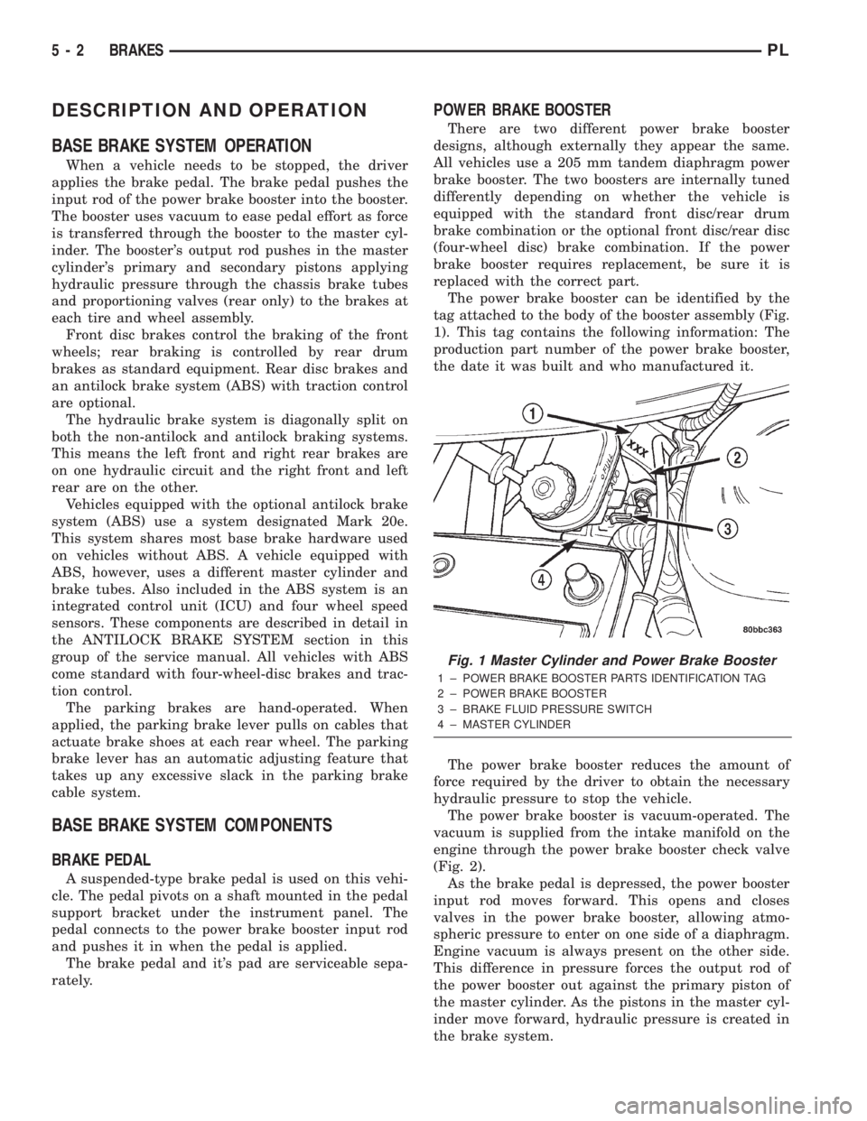
The power brake booster can be identified by the
tag attached to the body of the booster assembly (Fig.
1). This tag contains the following information: The
production part number of the power brake booster,
the date it was built and who manufactured it.
The power brake booster reduces the amount of
force required by the driver to obtain the necessary
hydraulic pressure to stop the vehicle.
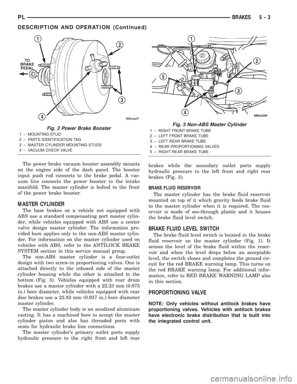
The power brake booster is vacuum-operated. The
vacuum is supplied from the intake manifold on the
engine through the power brake booster check valve
(Fig. 2).
As the brake pedal is depressed, the power booster
input rod moves forward. This opens and closes
valves in the power brake booster, allowing atmo-
spheric pressure to enter on one side of a diaphragm.
Engine vacuum is always present on the other side.
This difference in pressure forces the output rod of
the power booster out against the primary piston of
the master cylinder. As the pistons in the master cyl-
inder move forward, hydraulic pressure is created in
the brake system.
Fig. 1 Master Cylinder and Power Brake Booster
1 ± POWER BRAKE BOOSTER PARTS IDENTIFICATION TAG
2 ± POWER BRAKE BOOSTER
3 ± BRAKE FLUID PRESSURE SWITCH
4 ± MASTER CYLINDER
5 - 2 BRAKESPL
Page 82 of 1285

The power brake vacuum booster assembly mounts
on the engine side of the dash panel. The booster
input push rod connects to the brake pedal. A vac-
uum line connects the power booster to the intake
manifold. The master cylinder is bolted to the front
of the power brake booster.
MASTER CYLINDER
The base brakes on a vehicle not equipped with
ABS use a standard compensating port master cylin-
der, while vehicles equipped with ABS use a center
valve design master cylinder. The information pro-
vided here applies only to the non-ABS master cylin-
der. For information on the master cylinder used on
vehicles with ABS, refer to the ANTILOCK BRAKE
SYSTEM section in this service manual group.
The non-ABS master cylinder is a four-outlet
design with two screw-in proportioning valves. One is
attached directly to the inboard side of the master
cylinder housing while the other is attached to the
bottom (Fig. 3). Vehicles equipped with rear drum
brakes use a master cylinder with a 22.23 mm (0.875
in.) bore diameter, while vehicles equipped with rear
disc brakes use a 23.82 mm (0.937 in.) bore diameter
master cylinder.
The master cylinder body is an anodized aluminum
casting. It has a machined bore to accept the master
cylinder piston and also has threaded ports with
seats for hydraulic brake line connections.
The master cylinder's primary outlet ports supply
hydraulic pressure to the right front and left rearbrakes while the secondary outlet ports supply
hydraulic pressure to the left front and right rear
brakes (Fig. 3).
BRAKE FLUID RESERVOIR
The master cylinder has the brake fluid reservoir
mounted on top of it which gravity feeds brake fluid
to the master cylinder when it is required. The res-
ervoir is made of see-through plastic and it houses
the brake fluid level switch.
BRAKE FLUID LEVEL SWITCH
The brake fluid level switch is located in the brake
fluid reservoir on the master cylinder (Fig. 1). It
senses the level of the brake fluid within the reser-
voir and when the level drops below an acceptable
level, the switch closes and completes the ground cir-
cuit for the red BRAKE warning lamp. This turns on
the red BRAKE warning lamp. For additional infor-
mation, refer to RED BRAKE WARNING LAMP also
in this section.
PROPORTIONING VALVE
NOTE: Only vehicles without antilock brakes have
proportioning valves. Vehicles with antilock brakes
have electronic brake distribution that is built into
the integrated control unit.
Fig. 2 Power Brake Booster
1 ± MOUNTING STUD
2 ± PARTS IDENTIFICATION TAG
3 ± MASTER CYLINDER MOUNTING STUDS
4 ± VACUUM CHECK VALVE
Fig. 3 Non-ABS Master Cylinder
1 ± RIGHT FRONT BRAKE TUBE
2 ± LEFT FRONT BRAKE TUBE
3 ± LEFT REAR BRAKE TUBE
4 ± REAR PROPORTIONING VALVES
5 ± RIGHT REAR BRAKE TUBE
PLBRAKES 5 - 3
DESCRIPTION AND OPERATION (Continued)