2000 DODGE NEON brake fluid
[x] Cancel search: brake fluidPage 121 of 1285
REMOVAL
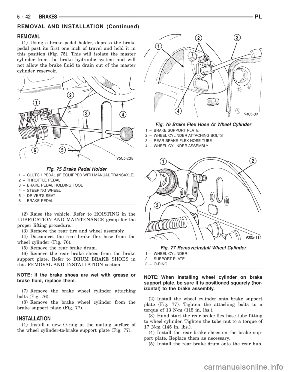
(1) Using a brake pedal holder, depress the brake
pedal past its first one inch of travel and hold it in
this position (Fig. 75). This will isolate the master
cylinder from the brake hydraulic system and will
not allow the brake fluid to drain out of the master
cylinder reservoir.
(2) Raise the vehicle. Refer to HOISTING in the
LUBRICATION AND MAINTENANCE group for the
proper lifting procedure.
(3) Remove the rear tire and wheel assembly.
(4) Disconnect the rear brake flex hose from the
wheel cylinder (Fig. 76).
(5) Remove the rear brake drum.
(6) Remove the rear brake shoes from the brake
support plate. Refer to DRUM BRAKE SHOES in
this REMOVAL AND INSTALLATION section.
NOTE: If the brake shoes are wet with grease or
brake fluid, replace them.
(7) Remove the brake wheel cylinder attaching
bolts (Fig. 76).
(8) Remove the brake wheel cylinder from the
brake support plate (Fig. 77).
INSTALLATION
(1) Install a new O-ring at the mating surface of
the wheel cylinder-to-brake support plate (Fig. 77).NOTE: When installing wheel cylinder on brake
support plate, be sure it is positioned squarely (hor-
izontal) to the brake assembly.
(2) Install the wheel cylinder onto brake support
plate (Fig. 77). Tighten the attaching bolts to a
torque of 13 N´m (115 in. lbs.).
(3) Hand start the rear brake flex hose tube fitting
to wheel cylinder. Tighten the tube nut to a torque of
17 N´m (145 in. lbs.).
(4) Install the rear brake shoes on the brake sup-
port plate. Replace them as necessary.
(5) Install the rear brake drum onto the rear hub.
Fig. 75 Brake Pedal Holder
1 ± CLUTCH PEDAL (IF EQUIPPED WITH MANUAL TRANSAXLE)
2 ± THROTTLE PEDAL
3 ± BRAKE PEDAL HOLDING TOOL
4 ± STEERING WHEEL
5 ± DRIVER'S SEAT
6 ± BRAKE PEDAL
Fig. 76 Brake Flex Hose At Wheel Cylinder
1 ± BRAKE SUPPORT PLATE
2 ± WHEEL CYLINDER ATTACHING BOLTS
3 ± REAR BRAKE FLEX HOSE TUBE
4 ± WHEEL CYLINDER ASSEMBLY
Fig. 77 Remove/Install Wheel Cylinder
1 ± WHEEL CYLINDER
2 ± SUPPORT PLATE
3 ± O-RING
5 - 42 BRAKESPL
REMOVAL AND INSTALLATION (Continued)
Page 125 of 1285
(4) Remove the brake drum (Fig. 87).
NOTE: If the drum does not come off, further brake
clearance can be obtained by backing off the brake
automatic adjuster screw. Remove the rubber plug
from the top of brake support plate. Rotate the
automatic adjuster screw in an upward motion,
using a screwdriver.
INSTALLATION
NOTE: Before installing the drum, inspect the brake
shoe linings for wear, shoe alignment, and contam-
ination.
(1) Install the rear brake drum on rear hub and
bearing (Fig. 87).
(2) Install the tire and wheel assembly. Tighten
the wheel mounting nuts to a torque of 135 N´m (100
ft. lbs.).
(3) Adjust the rear brake shoes as necessary. Refer
to ADJUSTMENTS in this section of this service
manual group.
(4) Lower the vehicle.
DRUM BRAKE SHOE SUPPORT PLATE (REAR)
NOTE: Before proceeding with this procedure,
review SERVICE WARNINGS AND CAUTIONS at the
beginning of REMOVAL AND INSTALLATION in this
section.
REMOVAL
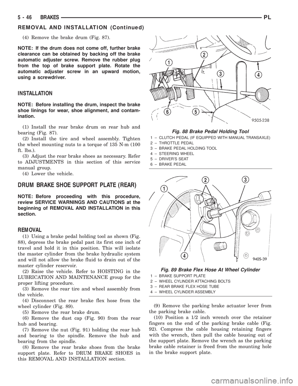
(1) Using a brake pedal holding tool as shown (Fig.
88), depress the brake pedal past its first one inch of
travel and hold it in this position. This will isolate
the master cylinder from the brake hydraulic system
and will not allow the brake fluid to drain out of the
master cylinder reservoir.
(2) Raise the vehicle. Refer to HOISTING in the
LUBRICATION AND MAINTENANCE group for the
proper lifting procedure.
(3) Remove the rear tire and wheel assembly from
the vehicle.
(4) Disconnect the rear brake flex hose from the
wheel cylinder (Fig. 89).
(5) Remove the rear brake drum.
(6) Remove the dust cap (Fig. 90) from the rear
hub and bearing.
(7) Remove the nut (Fig. 91) holding the rear hub
and bearing to the spindle. Remove the hub and
bearing from the spindle.
(8) Remove the rear brake shoes from the brake
support plate. Refer to DRUM BRAKE SHOES in
this REMOVAL AND INSTALLATION section.(9) Remove the parking brake actuator lever from
the parking brake cable.
(10) Position a 1/2 inch wrench over the retainer
fingers on the end of the parking brake cable (Fig.
92). Compress the cable housing retaining fingers
with the wrench, then pull the cable housing out of
the support plate. Remove the wrench as the parking
brake cable retainer is freed from the mounting hole
in the brake support plate.
Fig. 88 Brake Pedal Holding Tool
1 ± CLUTCH PEDAL (IF EQUIPPED WITH MANUAL TRANSAXLE)
2 ± THROTTLE PEDAL
3 ± BRAKE PEDAL HOLDING TOOL
4 ± STEERING WHEEL
5 ± DRIVER'S SEAT
6 ± BRAKE PEDAL
Fig. 89 Brake Flex Hose At Wheel Cylinder
1 ± BRAKE SUPPORT PLATE
2 ± WHEEL CYLINDER ATTACHING BOLTS
3 ± REAR BRAKE FLEX HOSE TUBE
4 ± WHEEL CYLINDER ASSEMBLY
5 - 46 BRAKESPL
REMOVAL AND INSTALLATION (Continued)
Page 136 of 1285
CALIPER PISTON AND SEALS
CALIPER PISTON REMOVAL
WARNING: UNDER NO CONDITION SHOULD HIGH
PRESSURE AIR EVER BE USED TO REMOVE A PIS-
TON FROM A CALIPER BORE. PERSONAL INJURY
COULD RESULT FROM SUCH A PRACTICE.
NOTE: The safest way to remove the piston from
the caliper bore is to use the hydraulic pressure of
the vehicle's brake system.
(1) Following the removal procedure in DISC
BRAKE SHOES found in this section, remove the
caliper from the brake rotor and hang the assembly
on a wire hook away from rotor and body of the vehi-
cle so brake fluid cannot get on these components.
Remove the brake shoes, and place a small piece of
wood between the piston and caliper fingers.
(2) Carefully depress the brake pedal to hydrauli-
cally push piston out of its bore. Once completed,
apply and hold down the brake pedal to any position
beyond the first inch of pedal travel using a brake
pedal holding tool. This will prevent the fluid in the
master cylinder reservoir from completely draining
out.(3) Disconnect the brake fluid flex hose from the
caliper assembly and remove it from the vehicle.
CALIPER SEAL REMOVAL
CAUTION: Do not use excessive force when clamp-
ing caliper in vise. Excessive vise pressure will
cause bore distortion.
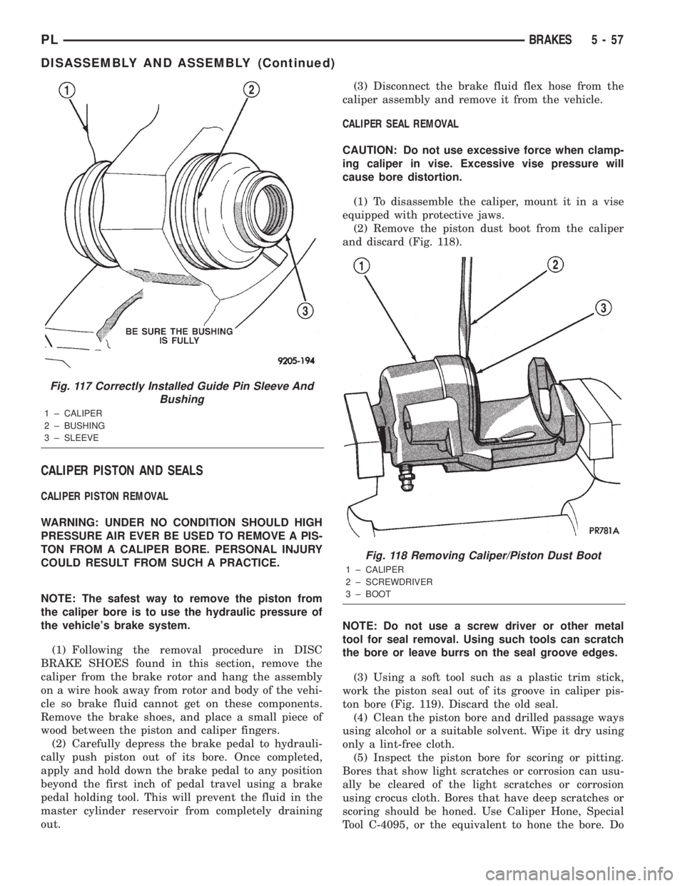
(1) To disassemble the caliper, mount it in a vise
equipped with protective jaws.
(2) Remove the piston dust boot from the caliper
and discard (Fig. 118).
NOTE: Do not use a screw driver or other metal
tool for seal removal. Using such tools can scratch
the bore or leave burrs on the seal groove edges.
(3) Using a soft tool such as a plastic trim stick,
work the piston seal out of its groove in caliper pis-
ton bore (Fig. 119). Discard the old seal.
(4) Clean the piston bore and drilled passage ways
using alcohol or a suitable solvent. Wipe it dry using
only a lint-free cloth.
(5) Inspect the piston bore for scoring or pitting.
Bores that show light scratches or corrosion can usu-
ally be cleared of the light scratches or corrosion
using crocus cloth. Bores that have deep scratches or
scoring should be honed. Use Caliper Hone, Special
Tool C-4095, or the equivalent to hone the bore. Do
Fig. 117 Correctly Installed Guide Pin Sleeve And
Bushing
1 ± CALIPER
2 ± BUSHING
3 ± SLEEVE
Fig. 118 Removing Caliper/Piston Dust Boot
1 ± CALIPER
2 ± SCREWDRIVER
3 ± BOOT
PLBRAKES 5 - 57
DISASSEMBLY AND ASSEMBLY (Continued)
Page 137 of 1285
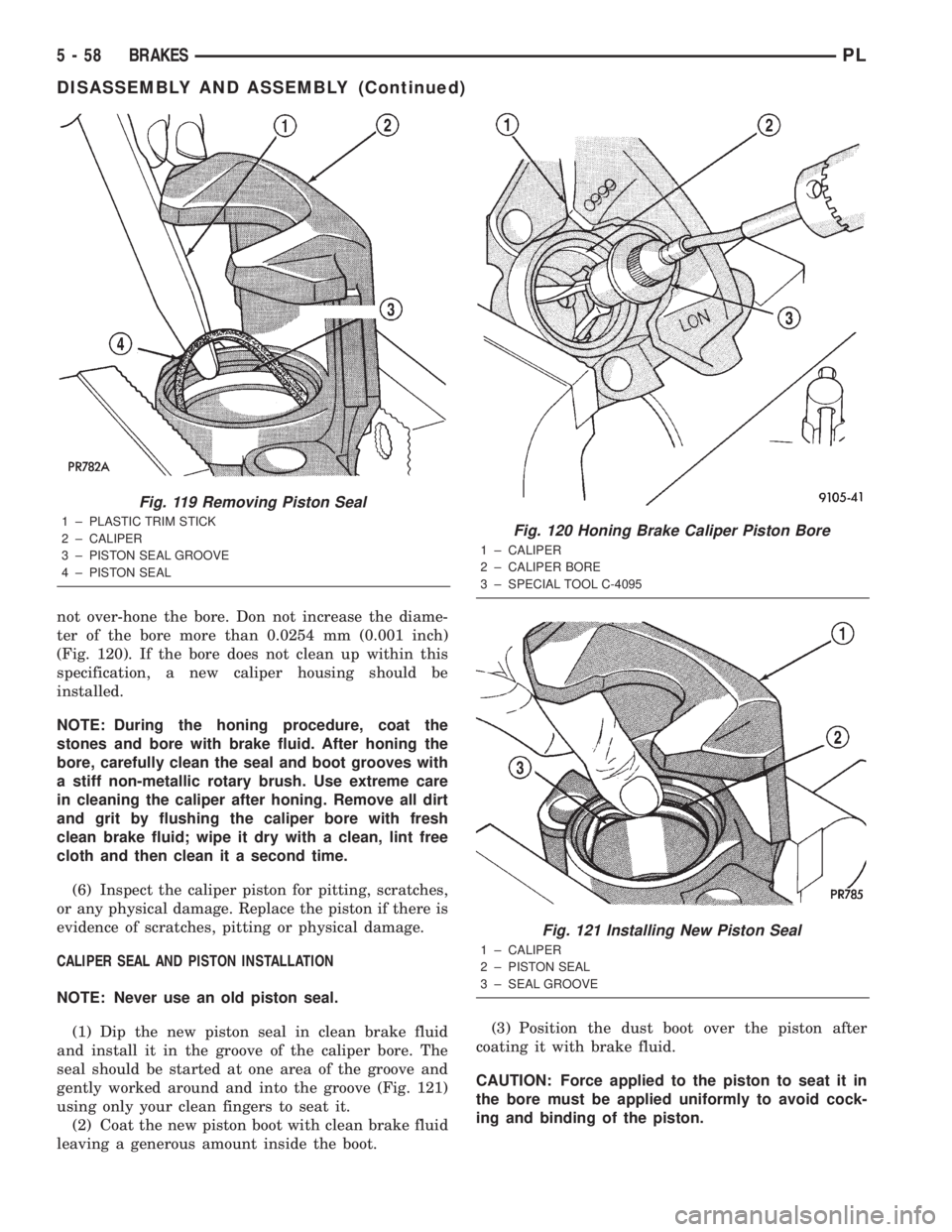
not over-hone the bore. Don not increase the diame-
ter of the bore more than 0.0254 mm (0.001 inch)
(Fig. 120). If the bore does not clean up within this
specification, a new caliper housing should be
installed.
NOTE: During the honing procedure, coat the
stones and bore with brake fluid. After honing the
bore, carefully clean the seal and boot grooves with
a stiff non-metallic rotary brush. Use extreme care
in cleaning the caliper after honing. Remove all dirt
and grit by flushing the caliper bore with fresh
clean brake fluid; wipe it dry with a clean, lint free
cloth and then clean it a second time.
(6) Inspect the caliper piston for pitting, scratches,
or any physical damage. Replace the piston if there is
evidence of scratches, pitting or physical damage.
CALIPER SEAL AND PISTON INSTALLATION
NOTE: Never use an old piston seal.
(1) Dip the new piston seal in clean brake fluid
and install it in the groove of the caliper bore. The
seal should be started at one area of the groove and
gently worked around and into the groove (Fig. 121)
using only your clean fingers to seat it.
(2) Coat the new piston boot with clean brake fluid
leaving a generous amount inside the boot.(3) Position the dust boot over the piston after
coating it with brake fluid.
CAUTION: Force applied to the piston to seat it in
the bore must be applied uniformly to avoid cock-
ing and binding of the piston.
Fig. 119 Removing Piston Seal
1 ± PLASTIC TRIM STICK
2 ± CALIPER
3 ± PISTON SEAL GROOVE
4 ± PISTON SEALFig. 120 Honing Brake Caliper Piston Bore
1 ± CALIPER
2 ± CALIPER BORE
3 ± SPECIAL TOOL C-4095
Fig. 121 Installing New Piston Seal
1 ± CALIPER
2 ± PISTON SEAL
3 ± SEAL GROOVE
5 - 58 BRAKESPL
DISASSEMBLY AND ASSEMBLY (Continued)
Page 139 of 1285
If the brake shoe assemblies do not require
replacement, reinstall the assemblies making sure
each brake shoe is returned to the original position.
Refer to DISC BRAKE SHOES in the REMOVAL
AND INSTALLATION section in this section of this
service manual group.
CALIPER INSPECTION
Check for brake fluid leaks in and around the boot
area. Check for any ruptures, brittleness or damage
to the piston dust boot. If the boot is damaged, or a
fluid leak is visible, disassemble the caliper assembly
and install a new seal and boot, and a piston if it is
scored. Refer to DISC BRAKE CALIPER in the DIS-
ASSEMBLY AND ASSEMBLY section in this section
of this service manual group.
Check the guide pin dust boots to determine if they
are in good condition. Replace if they are damaged,
dry, or found to be brittle. Refer to DISC BRAKE
CALIPER in the DISASSEMBLY AND ASSEMBLY
section in this section of this service manual group.
DISC BRAKES (REAR)
BRAKE SHOES
Clean the rear brake shoes and calipers with a
water-dampened cloth or with a brake cleaner. Do
not use a petroleum based product.
If a visual inspection does not adequately deter-
mine the condition of the lining, a physical check will
be necessary.
Remove the rear disc brake shoes. Refer to DISC
BRAKE SHOES in the REMOVAL AND INSTALLA-
TION section in this section of this service manual
group.
The combined brake shoe and lining material
thickness should be measured at the thinnest part of
the assembly.
When a set of brake shoes are worn to a total
thickness of approximately 7.0 mm (9/32 inch) or
less, they should be replaced.
Replace both brake shoe assemblies (inboard and
outboard). It is necessary that both front wheel sets
be replaced whenever brake shoe assemblies on
either side are replaced.
If the brake shoe assemblies do not require
replacement, reinstall the assemblies making sure
each brake shoe is returned to the original position.
Refer to DISC BRAKE SHOES in the REMOVAL
AND INSTALLATION section in this section of this
service manual group.
CALIPER INSPECTION
Check for brake fluid leaks in and around the boot
area. Check for any ruptures, brittleness or damage
to the piston dust boot. If the boot is damaged, or afluid leak is visible, disassemble the caliper assembly
and install a new seal and boot, and a piston if it is
scored. Refer to DISC BRAKE CALIPER in the DIS-
ASSEMBLY AND ASSEMBLY section in this section
of this service manual group.
Check the guide pin dust boots to determine if they
are in good condition. Replace if they are damaged,
dry, or found to be brittle. Refer to DISC BRAKE
CALIPER in the DISASSEMBLY AND ASSEMBLY
section in this section of this service manual group.
DRUM BRAKES (REAR)
BRAKE SHOES
Clean the rear brake shoes and springs with a
water-dampened cloth or with a brake cleaner. Do
not use a petroleum based product.
Rear brake shoe lining should show contact across
the entire width of the lining and also from the heel
to the toe of the lining. Replace the shoes if noted
otherwise.
Brake shoes with lack of contact at the toe or heel
of the brake shoe lining may be improperly ground.
Clean and inspect the brake support plate and
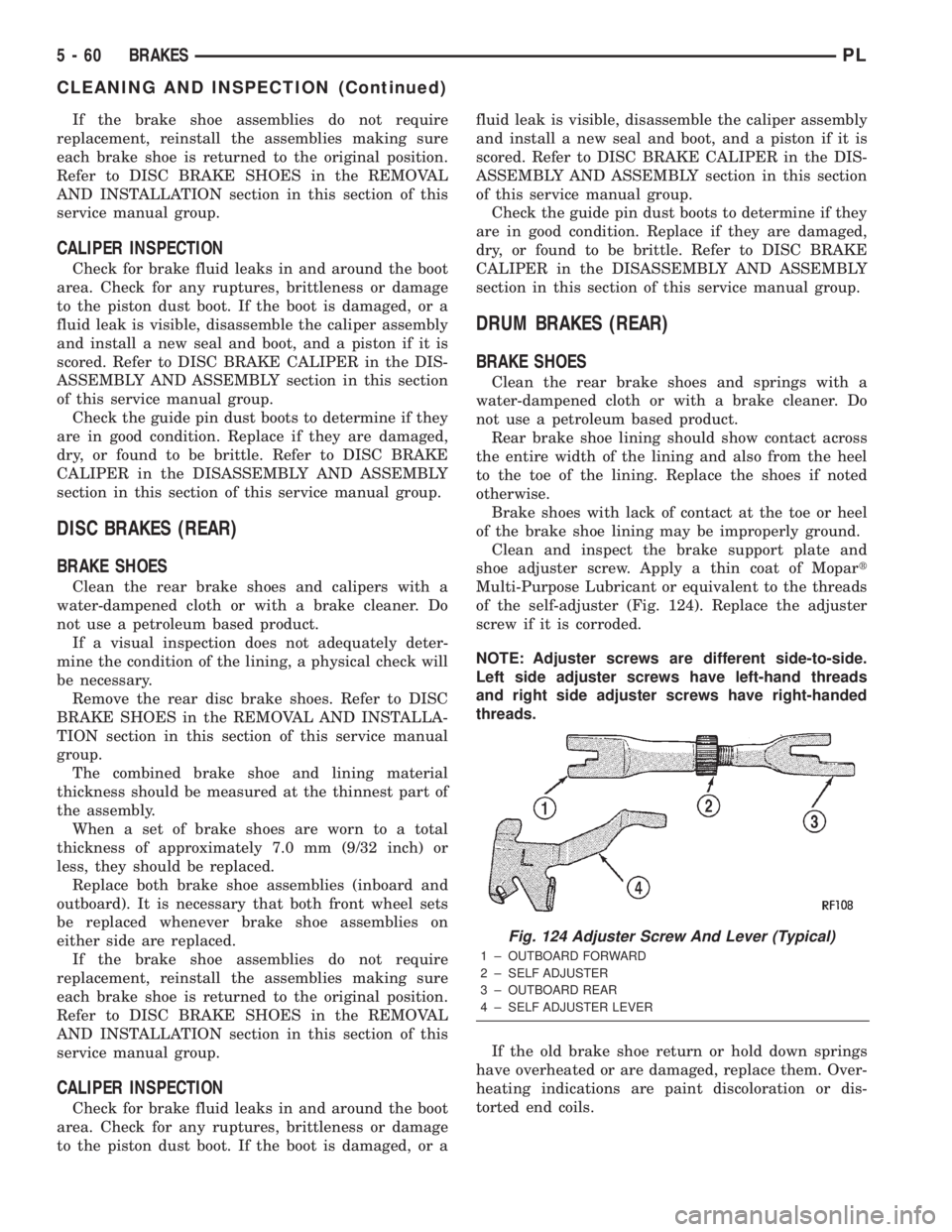
shoe adjuster screw. Apply a thin coat of Mopart
Multi-Purpose Lubricant or equivalent to the threads
of the self-adjuster (Fig. 124). Replace the adjuster
screw if it is corroded.
NOTE: Adjuster screws are different side-to-side.
Left side adjuster screws have left-hand threads
and right side adjuster screws have right-handed
threads.
If the old brake shoe return or hold down springs
have overheated or are damaged, replace them. Over-
heating indications are paint discoloration or dis-
torted end coils.
Fig. 124 Adjuster Screw And Lever (Typical)
1 ± OUTBOARD FORWARD
2 ± SELF ADJUSTER
3 ± OUTBOARD REAR
4 ± SELF ADJUSTER LEVER
5 - 60 BRAKESPL
CLEANING AND INSPECTION (Continued)
Page 140 of 1285
WHEEL CYLINDER
With the brake drums removed, inspect the wheel
cylinder boots for evidence of a brake fluid leak.
Visually check the boots for cuts, tears, or heat
cracks. If any of these conditions exist, the wheel cyl-
inders should be completely cleaned, inspected and
new parts installed.
If a wheel cylinder is leaking and the brake lining
material is saturated with brake fluid, the brake
shoes must be replaced.
ADJUSTMENTS
BRAKE LAMP SWITCH
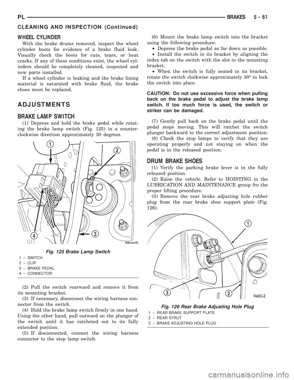
(1) Depress and hold the brake pedal while rotat-
ing the brake lamp switch (Fig. 125) in a counter-
clockwise direction approximately 30 degrees.
(2) Pull the switch rearward and remove it from
its mounting bracket.
(3) If necessary, disconnect the wiring harness con-
nector from the switch.
(4) Hold the brake lamp switch firmly in one hand.
Using the other hand, pull outward on the plunger of
the switch until it has ratcheted out to its fully
extended position.
(5) If disconnected, connect the wiring harness
connector to the stop lamp switch.(6) Mount the brake lamp switch into the bracket
using the following procedure:
²Depress the brake pedal as far down as possible.
²Install the switch in its bracket by aligning the
index tab on the switch with the slot in the mounting
bracket.
²When the switch is fully seated in its bracket,
rotate the switch clockwise approximately 30É to lock
the switch into place.
CAUTION: Do not use excessive force when pulling
back on the brake pedal to adjust the brake lamp
switch. If too much force is used, the switch or
striker can be damaged.
(7) Gently pull back on the brake pedal until the
pedal stops moving. This will ratchet the switch
plunger backward to the correct adjustment position.
(8) Check the stop lamps to verify that they are
operating properly and not staying on when the
pedal is in the released position.
DRUM BRAKE SHOES
(1) Verify the parking brake lever is in the fully
released position.
(2) Raise the vehicle. Refer to HOISTING in the
LUBRICATION AND MAINTENANCE group fro the
proper lifting procedure.
(3) Remove the rear brake adjusting hole rubber
plug from the rear brake shoe support plate (Fig.
126).
Fig. 125 Brake Lamp Switch
1 ± SWITCH
2 ± CLIP
3 ± BRAKE PEDAL
4 ± CONNECTOR
Fig. 126 Rear Brake Adjusting Hole Plug
1 ± REAR BRAKE SUPPORT PLATE
2 ± REAR STRUT
3 ± BRAKE ADJUSTING HOLE PLUG
PLBRAKES 5 - 61
CLEANING AND INSPECTION (Continued)
Page 142 of 1285
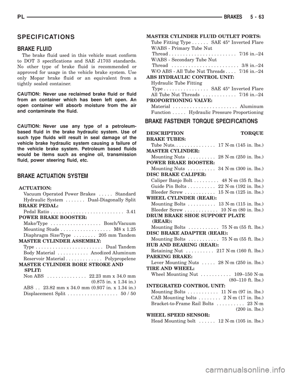
SPECIFICATIONS
BRAKE FLUID
The brake fluid used in this vehicle must conform
to DOT 3 specifications and SAE J1703 standards.
No other type of brake fluid is recommended or
approved for usage in the vehicle brake system. Use
only Mopar brake fluid or an equivalent from a
tightly sealed container.
CAUTION: Never use reclaimed brake fluid or fluid
from an container which has been left open. An
open container will absorb moisture from the air
and contaminate the fluid.
CAUTION: Never use any type of a petroleum-
based fluid in the brake hydraulic system. Use of
such type fluids will result in seal damage of the
vehicle brake hydraulic system causing a failure of
the vehicle brake system. Petroleum based fluids
would be items such as engine oil, transmission
fluid, power steering fluid, etc.
BRAKE ACTUATION SYSTEM
ACTUATION:
Vacuum Operated Power Brakes.....Standard
Hydraulic System.......Dual-Diagonally Split
BRAKE PEDAL:
Pedal Ratio..........................3.41
POWER BRAKE BOOSTER:
Make/Type..................Bosch/Vacuum
Mounting Studs.................. M8x1.25
Diaphragm Size/Type........ 205mmTandem
MASTER CYLINDER ASSEMBLY:
Type ........................Dual Tandem
Body Material...........Anodized Aluminum
Reservoir Material.............Polypropelene
MASTER CYLINDER BORE STROKE AND
SPLIT:
NonABS ..............22.23 mm x 34.0 mm
(0.875 in. x 1.34 in.)
ABS . . 23.82 mm x 34.0 mm (0.937 in. x 1.34 in.)
Displacement Split.................. 50/50MASTER CYLINDER FLUID OUTLET PORTS:
Tube Fitting Type...... SAE45ÉInverted Flare
W/ABS - Primary Tube Nut
Thread........................7/16 in.±24
W/ABS - Secondary Tube Nut
Thread........................ 3/8in.±24
W/O ABS - All Tube Nut Threads....7/16 in.±24
ABS HYDRAULIC CONTROL UNIT:
Hydraulic Tube Fitting
Type................ SAE45ÉInverted Flare
All Tube Nut Threads............7/16 in.±24
PROPORTIONING VALVE:
Material.......................Aluminum
Function.....Hydraulic Pressure Proportioning
BRAKE FASTENER TORQUE SPECIFICATIONS
DESCRIPTION TORQUE
BRAKE TUBES:
Tube Nuts............... 17N´m(145 in. lbs.)
MASTER CYLINDER:
Mounting Nuts.......... 28N´m(250 in. lbs.)
POWER BRAKE BOOSTER:
Mounting Nuts.......... 34N´m(300 in. lbs.)
DISC BRAKE CALIPER:
Caliper Banjo Bolt......... 48N´m(35ft.lbs.)
Guide Pin Bolts.......... 22N´m(192 in. lbs.)
Bleeder Screw........... 15N´m(125 in. lbs.)
WHEEL CYLINDER (REAR):
Mounting Bolts.......... 13N´m(115in.lbs.)
Bleeder Screw............ 10N´m(80in.lbs.)
DRUM BRAKE SHOE SUPPORT PLATE
(REAR):
Mounting Bolts........... 75N´m(55ft.lbs.)
DISC BRAKE ADAPTER (REAR):
Mounting Bolts........... 75N´m(55ft.lbs.)
HUB AND BEARING (REAR):
Retaining Nut.......... 217N´m(160 ft. lbs.)
PARKING BRAKE:
Lever Mounting Nuts..... 28N´m(250 in. lbs.)
TIRE AND WHEEL:
Wheel Mounting Nut...........109±150 N´m
(80±110 ft. lbs.)
INTEGRATED CONTROL UNIT:
Mounting Bolts........... 11N´m(97in.lbs.)
CAB Mounting bolts........ 2N´m(17in.lbs.)
Bracket-to-Frame Rail Bolts.......... 23N´m
(200 in. lbs.)
WHEEL SPEED SENSOR:
Head Mounting bolt...... 12N´m(105 in. lbs.)
PLBRAKES 5 - 63
Page 144 of 1285
ANTILOCK BRAKE SYSTEM
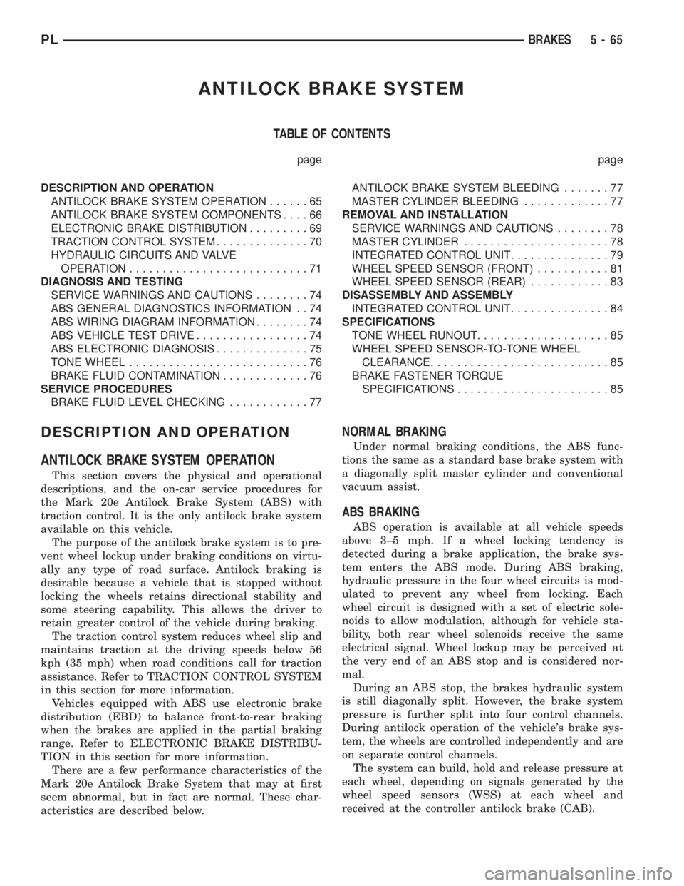
TABLE OF CONTENTS
page page
DESCRIPTION AND OPERATION
ANTILOCK BRAKE SYSTEM OPERATION......65
ANTILOCK BRAKE SYSTEM COMPONENTS....66
ELECTRONIC BRAKE DISTRIBUTION.........69
TRACTION CONTROL SYSTEM..............70
HYDRAULIC CIRCUITS AND VALVE
OPERATION...........................71
DIAGNOSIS AND TESTING
SERVICE WARNINGS AND CAUTIONS........74
ABS GENERAL DIAGNOSTICS INFORMATION . . 74
ABS WIRING DIAGRAM INFORMATION........74
ABS VEHICLE TEST DRIVE.................74
ABS ELECTRONIC DIAGNOSIS..............75
TONE WHEEL...........................76
BRAKE FLUID CONTAMINATION.............76
SERVICE PROCEDURES
BRAKE FLUID LEVEL CHECKING............77ANTILOCK BRAKE SYSTEM BLEEDING.......77
MASTER CYLINDER BLEEDING.............77
REMOVAL AND INSTALLATION
SERVICE WARNINGS AND CAUTIONS........78
MASTER CYLINDER......................78
INTEGRATED CONTROL UNIT...............79
WHEEL SPEED SENSOR (FRONT)...........81
WHEEL SPEED SENSOR (REAR)............83
DISASSEMBLY AND ASSEMBLY
INTEGRATED CONTROL UNIT...............84
SPECIFICATIONS
TONE WHEEL RUNOUT....................85
WHEEL SPEED SENSOR-TO-TONE WHEEL
CLEARANCE...........................85
BRAKE FASTENER TORQUE
SPECIFICATIONS.......................85
DESCRIPTION AND OPERATION
ANTILOCK BRAKE SYSTEM OPERATION
This section covers the physical and operational
descriptions, and the on-car service procedures for
the Mark 20e Antilock Brake System (ABS) with
traction control. It is the only antilock brake system
available on this vehicle.
The purpose of the antilock brake system is to pre-
vent wheel lockup under braking conditions on virtu-
ally any type of road surface. Antilock braking is
desirable because a vehicle that is stopped without
locking the wheels retains directional stability and
some steering capability. This allows the driver to
retain greater control of the vehicle during braking.
The traction control system reduces wheel slip and
maintains traction at the driving speeds below 56
kph (35 mph) when road conditions call for traction
assistance. Refer to TRACTION CONTROL SYSTEM
in this section for more information.
Vehicles equipped with ABS use electronic brake
distribution (EBD) to balance front-to-rear braking
when the brakes are applied in the partial braking
range. Refer to ELECTRONIC BRAKE DISTRIBU-
TION in this section for more information.
There are a few performance characteristics of the
Mark 20e Antilock Brake System that may at first
seem abnormal, but in fact are normal. These char-
acteristics are described below.
NORMAL BRAKING
Under normal braking conditions, the ABS func-
tions the same as a standard base brake system with
a diagonally split master cylinder and conventional
vacuum assist.
ABS BRAKING
ABS operation is available at all vehicle speeds
above 3±5 mph. If a wheel locking tendency is
detected during a brake application, the brake sys-
tem enters the ABS mode. During ABS braking,
hydraulic pressure in the four wheel circuits is mod-
ulated to prevent any wheel from locking. Each
wheel circuit is designed with a set of electric sole-
noids to allow modulation, although for vehicle sta-
bility, both rear wheel solenoids receive the same
electrical signal. Wheel lockup may be perceived at
the very end of an ABS stop and is considered nor-
mal.
During an ABS stop, the brakes hydraulic system
is still diagonally split. However, the brake system
pressure is further split into four control channels.
During antilock operation of the vehicle's brake sys-
tem, the wheels are controlled independently and are
on separate control channels.
The system can build, hold and release pressure at
each wheel, depending on signals generated by the
wheel speed sensors (WSS) at each wheel and
received at the controller antilock brake (CAB).
PLBRAKES 5 - 65