2000 DODGE NEON brake fluid
[x] Cancel search: brake fluidPage 99 of 1285
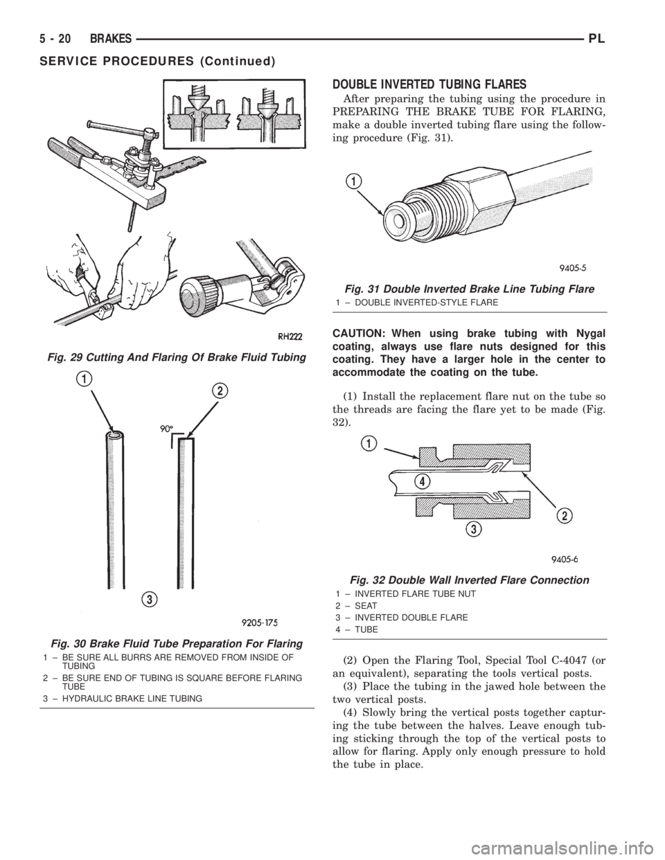
DOUBLE INVERTED TUBING FLARES
After preparing the tubing using the procedure in
PREPARING THE BRAKE TUBE FOR FLARING,
make a double inverted tubing flare using the follow-
ing procedure (Fig. 31).
CAUTION: When using brake tubing with Nygal
coating, always use flare nuts designed for this
coating. They have a larger hole in the center to
accommodate the coating on the tube.
(1) Install the replacement flare nut on the tube so
the threads are facing the flare yet to be made (Fig.
32).
(2) Open the Flaring Tool, Special Tool C-4047 (or
an equivalent), separating the tools vertical posts.
(3) Place the tubing in the jawed hole between the
two vertical posts.
(4) Slowly bring the vertical posts together captur-
ing the tube between the halves. Leave enough tub-
ing sticking through the top of the vertical posts to
allow for flaring. Apply only enough pressure to hold
the tube in place.
Fig. 29 Cutting And Flaring Of Brake Fluid Tubing
Fig. 30 Brake Fluid Tube Preparation For Flaring
1 ± BE SURE ALL BURRS ARE REMOVED FROM INSIDE OF
TUBING
2 ± BE SURE END OF TUBING IS SQUARE BEFORE FLARING
TUBE
3 ± HYDRAULIC BRAKE LINE TUBING
Fig. 31 Double Inverted Brake Line Tubing Flare
1 ± DOUBLE INVERTED-STYLE FLARE
Fig. 32 Double Wall Inverted Flare Connection
1 ± INVERTED FLARE TUBE NUT
2 ± SEAT
3 ± INVERTED DOUBLE FLARE
4 ± TUBE
5 - 20 BRAKESPL
SERVICE PROCEDURES (Continued)
Page 102 of 1285
ADJUSTER UNLOADING (UNLOCKING)
NOTE: The parking brake lever can only be in the
released position when releasing the automatic
adjuster locking pin or pin punch.
(1) Be sure the rear parking brake cables are both
properly installed in the equalizer.
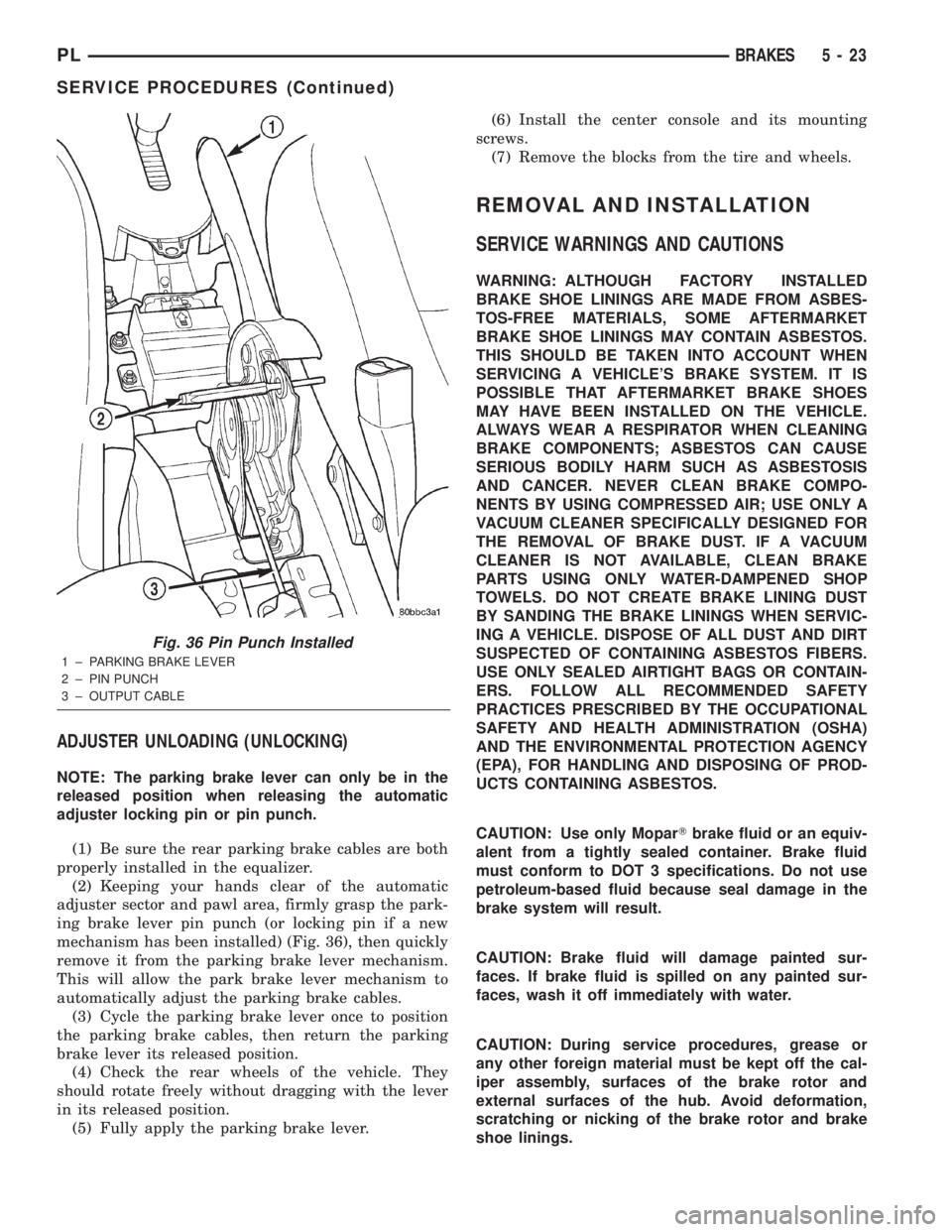
(2) Keeping your hands clear of the automatic
adjuster sector and pawl area, firmly grasp the park-
ing brake lever pin punch (or locking pin if a new
mechanism has been installed) (Fig. 36), then quickly
remove it from the parking brake lever mechanism.
This will allow the park brake lever mechanism to
automatically adjust the parking brake cables.
(3) Cycle the parking brake lever once to position
the parking brake cables, then return the parking
brake lever its released position.
(4) Check the rear wheels of the vehicle. They
should rotate freely without dragging with the lever
in its released position.
(5) Fully apply the parking brake lever.(6) Install the center console and its mounting
screws.
(7) Remove the blocks from the tire and wheels.
REMOVAL AND INSTALLATION
SERVICE WARNINGS AND CAUTIONS
WARNING: ALTHOUGH FACTORY INSTALLED
BRAKE SHOE LININGS ARE MADE FROM ASBES-
TOS-FREE MATERIALS, SOME AFTERMARKET
BRAKE SHOE LININGS MAY CONTAIN ASBESTOS.
THIS SHOULD BE TAKEN INTO ACCOUNT WHEN
SERVICING A VEHICLE'S BRAKE SYSTEM. IT IS
POSSIBLE THAT AFTERMARKET BRAKE SHOES
MAY HAVE BEEN INSTALLED ON THE VEHICLE.
ALWAYS WEAR A RESPIRATOR WHEN CLEANING
BRAKE COMPONENTS; ASBESTOS CAN CAUSE
SERIOUS BODILY HARM SUCH AS ASBESTOSIS
AND CANCER. NEVER CLEAN BRAKE COMPO-
NENTS BY USING COMPRESSED AIR; USE ONLY A
VACUUM CLEANER SPECIFICALLY DESIGNED FOR
THE REMOVAL OF BRAKE DUST. IF A VACUUM
CLEANER IS NOT AVAILABLE, CLEAN BRAKE
PARTS USING ONLY WATER-DAMPENED SHOP
TOWELS. DO NOT CREATE BRAKE LINING DUST
BY SANDING THE BRAKE LININGS WHEN SERVIC-
ING A VEHICLE. DISPOSE OF ALL DUST AND DIRT
SUSPECTED OF CONTAINING ASBESTOS FIBERS.
USE ONLY SEALED AIRTIGHT BAGS OR CONTAIN-
ERS. FOLLOW ALL RECOMMENDED SAFETY
PRACTICES PRESCRIBED BY THE OCCUPATIONAL
SAFETY AND HEALTH ADMINISTRATION (OSHA)
AND THE ENVIRONMENTAL PROTECTION AGENCY
(EPA), FOR HANDLING AND DISPOSING OF PROD-
UCTS CONTAINING ASBESTOS.
CAUTION: Use only MoparTbrake fluid or an equiv-
alent from a tightly sealed container. Brake fluid
must conform to DOT 3 specifications. Do not use
petroleum-based fluid because seal damage in the
brake system will result.
CAUTION: Brake fluid will damage painted sur-
faces. If brake fluid is spilled on any painted sur-
faces, wash it off immediately with water.
CAUTION: During service procedures, grease or
any other foreign material must be kept off the cal-
iper assembly, surfaces of the brake rotor and
external surfaces of the hub. Avoid deformation,
scratching or nicking of the brake rotor and brake
shoe linings.
Fig. 36 Pin Punch Installed
1 ± PARKING BRAKE LEVER
2 ± PIN PUNCH
3 ± OUTPUT CABLE
PLBRAKES 5 - 23
SERVICE PROCEDURES (Continued)
Page 107 of 1285
(4) Gently pull back on the brake pedal until the
pedal stops moving. This will ratchet the switch
plunger backward to the correct adjustment position.
(5) Check the stop lamps to verify they are operat-
ing properly and not staying on when the pedal is in
the released position.
MASTER CYLINDER
NOTE: Before proceeding with this procedure,
review SERVICE WARNINGS AND CAUTIONS at the
beginning of REMOVAL AND INSTALLATION in this
section.
REMOVAL
CAUTION: The vacuum in the power brake booster
must be pumped down before removing the master
cylinder to prevent the booster from sucking in any
contamination. This can be done by pumping the
brake pedal while the engine is not running until a
firm brake pedal is achieved.
(1) With the engine not running, pump the brake
pedal 4-5 strokes until the pedal feel is firm.
(2) Disconnect the negative (ground) cable from
the battery and isolate the cable.
(3) Disconnect the positive cable from the battery,
then remove the battery from the battery tray. There
is one nut securing the clamp on the backside of the
battery holding it in place.
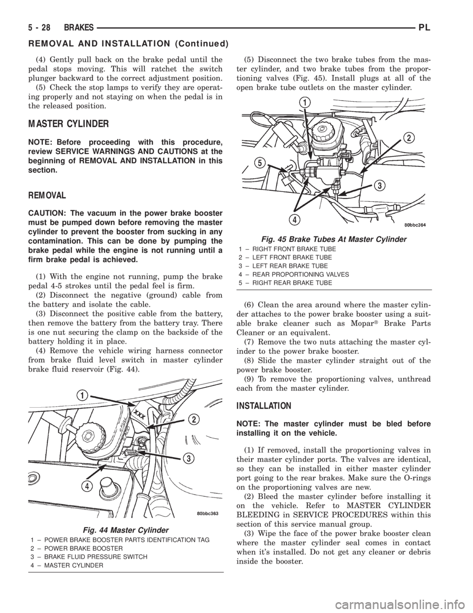
(4) Remove the vehicle wiring harness connector
from brake fluid level switch in master cylinder
brake fluid reservoir (Fig. 44).(5) Disconnect the two brake tubes from the mas-
ter cylinder, and two brake tubes from the propor-
tioning valves (Fig. 45). Install plugs at all of the
open brake tube outlets on the master cylinder.
(6) Clean the area around where the master cylin-
der attaches to the power brake booster using a suit-
able brake cleaner such as MopartBrake Parts
Cleaner or an equivalent.
(7) Remove the two nuts attaching the master cyl-
inder to the power brake booster.
(8) Slide the master cylinder straight out of the
power brake booster.
(9) To remove the proportioning valves, unthread
each from the master cylinder.
INSTALLATION
NOTE: The master cylinder must be bled before
installing it on the vehicle.
(1) If removed, install the proportioning valves in
their master cylinder ports. The valves are identical,
so they can be installed in either master cylinder
port going to the rear brakes. Make sure the O-rings
on the proportioning valves are new.
(2) Bleed the master cylinder before installing it
on the vehicle. Refer to MASTER CYLINDER
BLEEDING in SERVICE PROCEDURES within this
section of this service manual group.
(3) Wipe the face of the power brake booster clean
where the master cylinder seal comes in contact
when it's installed. Do not get any cleaner or debris
inside the booster.
Fig. 44 Master Cylinder
1 ± POWER BRAKE BOOSTER PARTS IDENTIFICATION TAG
2 ± POWER BRAKE BOOSTER
3 ± BRAKE FLUID PRESSURE SWITCH
4 ± MASTER CYLINDER
Fig. 45 Brake Tubes At Master Cylinder
1 ± RIGHT FRONT BRAKE TUBE
2 ± LEFT FRONT BRAKE TUBE
3 ± LEFT REAR BRAKE TUBE
4 ± REAR PROPORTIONING VALVES
5 ± RIGHT REAR BRAKE TUBE
5 - 28 BRAKESPL
REMOVAL AND INSTALLATION (Continued)
Page 108 of 1285
(4) Position the master cylinder on the studs of the
power brake booster, aligning the push rod of the
power brake booster with master cylinder piston
push rod. Carefully push the master cylinder onto
the studs until it contacts the face of the booster.
(5) Install the two master cylinder mounting nuts
and tighten each to a torque of 28 N´m (250 in. lbs.).
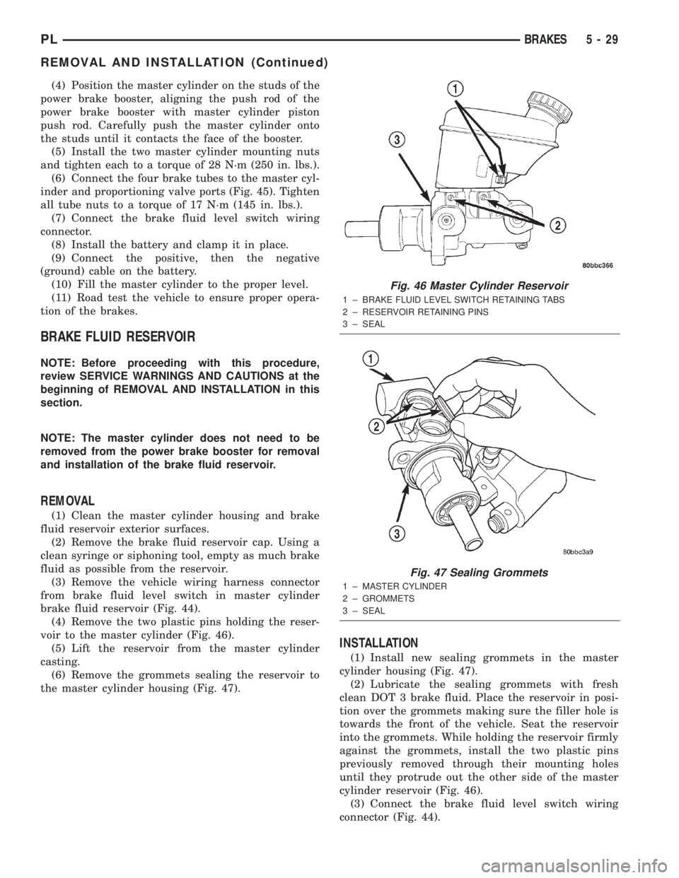
(6) Connect the four brake tubes to the master cyl-
inder and proportioning valve ports (Fig. 45). Tighten
all tube nuts to a torque of 17 N´m (145 in. lbs.).
(7) Connect the brake fluid level switch wiring
connector.
(8) Install the battery and clamp it in place.
(9) Connect the positive, then the negative
(ground) cable on the battery.
(10) Fill the master cylinder to the proper level.
(11) Road test the vehicle to ensure proper opera-
tion of the brakes.
BRAKE FLUID RESERVOIR
NOTE: Before proceeding with this procedure,
review SERVICE WARNINGS AND CAUTIONS at the
beginning of REMOVAL AND INSTALLATION in this
section.
NOTE: The master cylinder does not need to be
removed from the power brake booster for removal
and installation of the brake fluid reservoir.
REMOVAL
(1) Clean the master cylinder housing and brake
fluid reservoir exterior surfaces.
(2) Remove the brake fluid reservoir cap. Using a
clean syringe or siphoning tool, empty as much brake
fluid as possible from the reservoir.
(3) Remove the vehicle wiring harness connector
from brake fluid level switch in master cylinder
brake fluid reservoir (Fig. 44).
(4) Remove the two plastic pins holding the reser-
voir to the master cylinder (Fig. 46).
(5) Lift the reservoir from the master cylinder
casting.
(6) Remove the grommets sealing the reservoir to
the master cylinder housing (Fig. 47).
INSTALLATION
(1) Install new sealing grommets in the master
cylinder housing (Fig. 47).
(2) Lubricate the sealing grommets with fresh
clean DOT 3 brake fluid. Place the reservoir in posi-
tion over the grommets making sure the filler hole is
towards the front of the vehicle. Seat the reservoir
into the grommets. While holding the reservoir firmly
against the grommets, install the two plastic pins
previously removed through their mounting holes
until they protrude out the other side of the master
cylinder reservoir (Fig. 46).
(3) Connect the brake fluid level switch wiring
connector (Fig. 44).
Fig. 46 Master Cylinder Reservoir
1 ± BRAKE FLUID LEVEL SWITCH RETAINING TABS
2 ± RESERVOIR RETAINING PINS
3 ± SEAL
Fig. 47 Sealing Grommets
1 ± MASTER CYLINDER
2 ± GROMMETS
3 ± SEAL
PLBRAKES 5 - 29
REMOVAL AND INSTALLATION (Continued)
Page 109 of 1285
(4) Fill the reservoir with fresh clean DOT 3 brake
fluid. Refer to BRAKE FLUID LEVEL CHECKING
in the SERVICE PROCEDURES section in this sec-
tion of this service manual group.
BRAKE FLUID LEVEL SWITCH
NOTE: Before proceeding with this procedure,
review SERVICE WARNINGS AND CAUTIONS at the
beginning of REMOVAL AND INSTALLATION in this
section.
REMOVAL
(1) Remove the vehicle wiring harness connector
from brake fluid level switch in master cylinder
brake fluid reservoir (Fig. 44).
(2) Push together the retaining tabs holding the
brake fluid level switch in place in the brake fluid
reservoir (Fig. 46).
(3) Pull the brake fluid level switch out the other
side of the reservoir.
INSTALLATION
(1) Align the brake fluid level switch with its
mounting hole on the left side of the master cylinder
brake fluid reservoir. Push the switch into the fluid
reservoir until the switch retaining tabs are
expanded on the other side of the reservoir, locking it
in place (Fig. 46).
(2) Connect the brake fluid level switch wiring
connector (Fig. 44).
POWER BRAKE BOOSTER
NOTE: Before proceeding with this procedure,
review SERVICE WARNINGS AND CAUTIONS at the
beginning of REMOVAL AND INSTALLATION in this
section.
REMOVAL
(1) Disconnect negative (ground) cable from the
battery and isolate the cable.
(2) Disconnect the positive cable from the battery,
then remove the battery from the battery tray. There
is one nut securing the clamp on the backside of the
battery holding it in place.
(3) Remove the one nut and one bolt securing the
air cleaner box in place, then disconnect the wiring
harness connector at the air inlet sensor.
(4) Lift the air cleaner box upward enough to clear
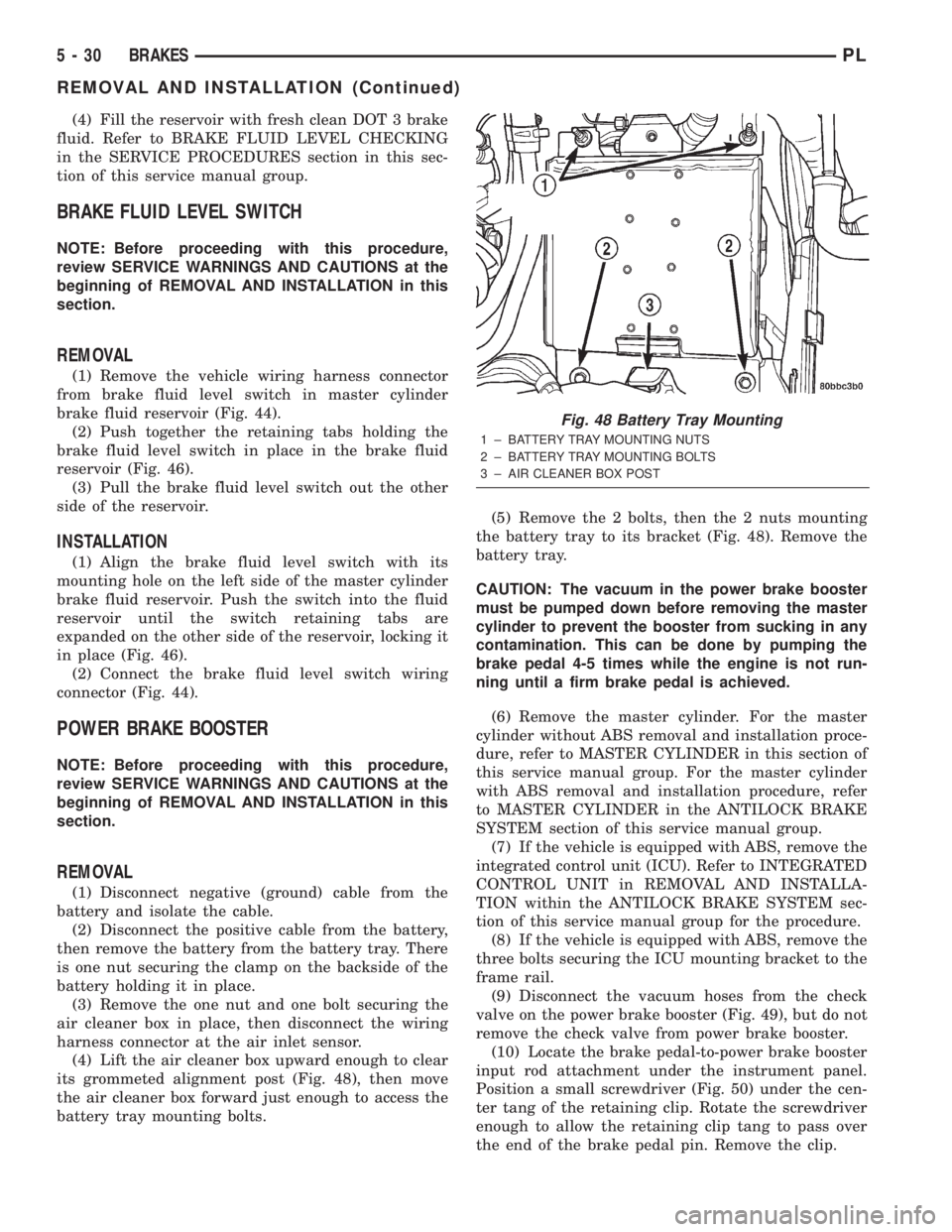
its grommeted alignment post (Fig. 48), then move
the air cleaner box forward just enough to access the
battery tray mounting bolts.(5) Remove the 2 bolts, then the 2 nuts mounting
the battery tray to its bracket (Fig. 48). Remove the
battery tray.
CAUTION: The vacuum in the power brake booster
must be pumped down before removing the master
cylinder to prevent the booster from sucking in any
contamination. This can be done by pumping the
brake pedal 4-5 times while the engine is not run-
ning until a firm brake pedal is achieved.
(6) Remove the master cylinder. For the master
cylinder without ABS removal and installation proce-
dure, refer to MASTER CYLINDER in this section of
this service manual group. For the master cylinder
with ABS removal and installation procedure, refer
to MASTER CYLINDER in the ANTILOCK BRAKE
SYSTEM section of this service manual group.
(7) If the vehicle is equipped with ABS, remove the
integrated control unit (ICU). Refer to INTEGRATED
CONTROL UNIT in REMOVAL AND INSTALLA-
TION within the ANTILOCK BRAKE SYSTEM sec-
tion of this service manual group for the procedure.
(8) If the vehicle is equipped with ABS, remove the
three bolts securing the ICU mounting bracket to the
frame rail.
(9) Disconnect the vacuum hoses from the check
valve on the power brake booster (Fig. 49), but do not
remove the check valve from power brake booster.
(10) Locate the brake pedal-to-power brake booster
input rod attachment under the instrument panel.
Position a small screwdriver (Fig. 50) under the cen-
ter tang of the retaining clip. Rotate the screwdriver
enough to allow the retaining clip tang to pass over
the end of the brake pedal pin. Remove the clip.
Fig. 48 Battery Tray Mounting
1 ± BATTERY TRAY MOUNTING NUTS
2 ± BATTERY TRAY MOUNTING BOLTS
3 ± AIR CLEANER BOX POST
5 - 30 BRAKESPL
REMOVAL AND INSTALLATION (Continued)
Page 111 of 1285
CAUTION: Use only a new brake booster input rod-
to-brake pedal retaining clip to ensure proper
retainment.
(4) Connect the power brake booster input rod-to-
brake pedal pin. Install a new retaining clip. Do not
use the old clip.
(5) Connect all previously removed vacuum hoses
to the vacuum check valve (Fig. 49).
(6) If the vehicle is equipped with ABS, install the
ICU mounting bracket on the frame rail using its
three bolts. Tighten the nuts to a torque of 23 N´m
(200 in. lbs.).
(7) If the vehicle is equipped with ABS, reinstall
the ICU. Refer to INTEGRATED CONTROL UNIT in
REMOVAL AND INSTALLATION within the
ANTILOCK BRAKE SYSTEM section of this service
manual group for the procedure.
(8) Install the master cylinder. For the master cyl-
inder without ABS removal and installation proce-
dure, refer to MASTER CYLINDER in this section of
this service manual group. For the master cylinder
with ABS removal and installation procedure, refer
to MASTER CYLINDER in the ANTILOCK BRAKE
SYSTEM section of this service manual group.
(9) Position the battery tray back in place. Install
the two bolts, then the two nuts mounting the bat-
tery tray to its bracket (Fig. 48). Tighten the two
bolts and nuts to a torque of 34 N´m (25 ft. lbs.).
(10) Reinstall the air cleaner box onto its grom-
meted alignment post (Fig. 48).
(11) Install the one nut and one bolt securing the
air cleaner box in place, then connect the wiring har-
ness connector at the air inlet sensor.
(12) Install the battery and clamp it in place.
(13) Connect the positive, then the negative
(ground) cable on the battery.
(14) Adjust the stop lamp switch as necessary.
Refer to STOP LAMP SWITCH in the ADJUST-
MENTS section of this group.
(15) Bleed the base brake system.
(16) Road test the vehicle to ensure proper opera-
tion of the brakes.
PROPORTIONING VALVE
NOTE: Before proceeding with this procedure,
review SERVICE WARNINGS AND CAUTIONS at the
beginning of REMOVAL AND INSTALLATION in this
section.
REMOVAL
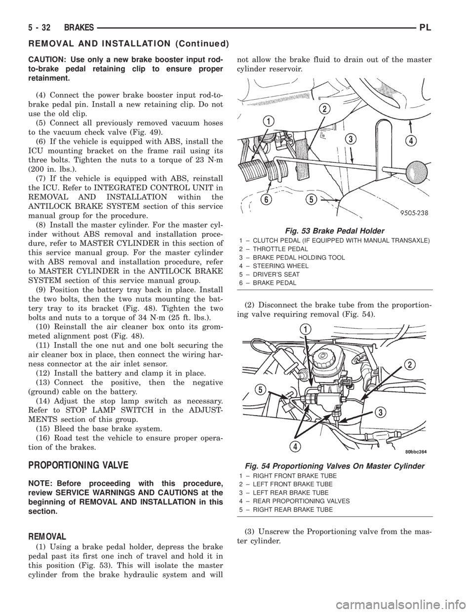
(1) Using a brake pedal holder, depress the brake
pedal past its first one inch of travel and hold it in
this position (Fig. 53). This will isolate the master
cylinder from the brake hydraulic system and willnot allow the brake fluid to drain out of the master
cylinder reservoir.
(2) Disconnect the brake tube from the proportion-
ing valve requiring removal (Fig. 54).
(3) Unscrew the Proportioning valve from the mas-
ter cylinder.
Fig. 53 Brake Pedal Holder
1 ± CLUTCH PEDAL (IF EQUIPPED WITH MANUAL TRANSAXLE)
2 ± THROTTLE PEDAL
3 ± BRAKE PEDAL HOLDING TOOL
4 ± STEERING WHEEL
5 ± DRIVER'S SEAT
6 ± BRAKE PEDAL
Fig. 54 Proportioning Valves On Master Cylinder
1 ± RIGHT FRONT BRAKE TUBE
2 ± LEFT FRONT BRAKE TUBE
3 ± LEFT REAR BRAKE TUBE
4 ± REAR PROPORTIONING VALVES
5 ± RIGHT REAR BRAKE TUBE
5 - 32 BRAKESPL
REMOVAL AND INSTALLATION (Continued)
Page 112 of 1285
INSTALLATION
(1) Lubricate the O-ring on the proportioning
valve. Make sure the O-ring on the proportioning
valve is new.
(2) Install the proportioning valve in its master
cylinder port. Tighten the proportioning valve to a
torque of 40 N´m (30 ft. lbs.).
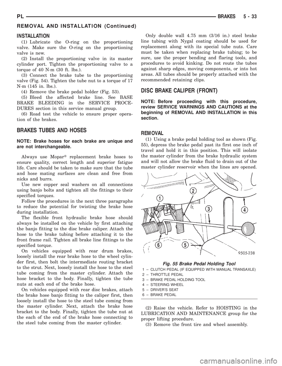
(3) Connect the brake tube to the proportioning
valve (Fig. 54). Tighten the tube nut to a torque of 17
N´m (145 in. lbs.).
(4) Remove the brake pedal holder (Fig. 53).
(5) Bleed the affected brake line. See BASE
BRAKE BLEEDING in the SERVICE PROCE-
DURES section in this service manual group.
(6) Road test the vehicle to ensure proper opera-
tion of the brakes.
BRAKES TUBES AND HOSES
NOTE: Brake hoses for each brake are unique and
are not interchangeable.
Always use Mopartreplacement brake hoses to
ensure quality, correct length and superior fatigue
life. Care should be taken to make sure that the tube
and hose mating surfaces are clean and free from
nicks and burrs.
Use new copper seal washers on all connections
using banjo bolts and tighten all the fittings to their
specified torques.
Follow the procedures in the next three paragraphs
to reduce the potential for twisting the brake hose
during installation.
The flexible front hydraulic brake hose should
always be installed on the vehicle by first attaching
the banjo fitting to the disc brake caliper. Attach the
hose to the brake tubing before attaching it to the
front frame rail. Tighten all brake line fittings to the
specified torque.
On vehicles equipped with rear drum brakes,
loosely install the rear brake hose to the wheel cylin-
der first, then bolt the intermediate routing bracket
to the strut. Next, loosely install the hose to the steel
tube coming from the master cylinder. Attach the
hose bracket to the body. Finally, tighten the tube
nuts at each end of the brake hose.
On vehicles equipped with rear disc brakes, attach
the brake hose banjo fitting to the caliper first, then
loosely install the hose to the steel tube coming from
the master cylinder. Next, attach the brake hose
bracket to the body. Finally, tighten the tube nut at
the each of the end of the brake hose connecting to
the steel tube coming from the master cylinder.Only double wall 4.75 mm (3/16 in.) steel brake
line tubing with Nygal coating should be used for
replacement along with its special tube nuts. Care
must be taken when replacing brake tubing; to be
sure, use the proper bending and flaring tools, and
procedures to avoid kinking. Do not route the tubes
against sharp edges, moving components, or into hot
areas. All tubes should be properly attached with the
recommended retaining clips.
DISC BRAKE CALIPER (FRONT)
NOTE: Before proceeding with this procedure,
review SERVICE WARNINGS AND CAUTIONS at the
beginning of REMOVAL AND INSTALLATION in this
section.
REMOVAL
(1) Using a brake pedal holding tool as shown (Fig.
55), depress the brake pedal past its first one inch of
travel and hold it in this position. This will isolate
the master cylinder from the brake hydraulic system
and will not allow the brake fluid to drain out of the
master cylinder reservoir when the lines are opened.
(2) Raise the vehicle. Refer to HOISTING in the
LUBRICATION AND MAINTENANCE group for the
proper lifting procedure.
(3) Remove the front tire and wheel assembly.
Fig. 55 Brake Pedal Holding Tool
1 ± CLUTCH PEDAL (IF EQUIPPED WITH MANUAL TRANSAXLE)
2 ± THROTTLE PEDAL
3 ± BRAKE PEDAL HOLDING TOOL
4 ± STEERING WHEEL
5 ± DRIVER'S SEAT
6 ± BRAKE PEDAL
PLBRAKES 5 - 33
REMOVAL AND INSTALLATION (Continued)
Page 117 of 1285
DISC BRAKE CALIPER (REAR)
REMOVAL
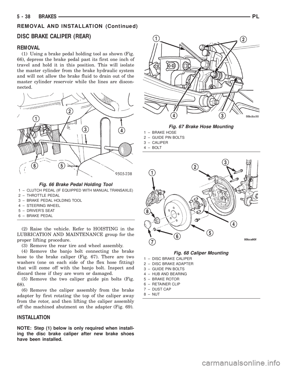
(1) Using a brake pedal holding tool as shown (Fig.
66), depress the brake pedal past its first one inch of
travel and hold it in this position. This will isolate
the master cylinder from the brake hydraulic system
and will not allow the brake fluid to drain out of the
master cylinder reservoir while the lines are discon-
nected.
(2) Raise the vehicle. Refer to HOISTING in the
LUBRICATION AND MAINTENANCE group for the
proper lifting procedure.
(3) Remove the rear tire and wheel assembly.
(4) Remove the banjo bolt connecting the brake
hose to the brake caliper (Fig. 67). There are two
washers (one on each side of the flex hose fitting)
that will come off with the banjo bolt. Inspect and
discard these if they are worn or damaged.
(5) Remove the two caliper guide pin bolts (Fig.
68).
(6) Remove the caliper assembly from the brake
adapter by first rotating the top of the caliper away
from the rotor, and then lifting the caliper assembly
off the machined abutment on the adapter (Fig. 69).
INSTALLATION
NOTE: Step (1) below is only required when install-
ing the disc brake caliper after new brake shoes
have been installed.
Fig. 66 Brake Pedal Holding Tool
1 ± CLUTCH PEDAL (IF EQUIPPED WITH MANUAL TRANSAXLE)
2 ± THROTTLE PEDAL
3 ± BRAKE PEDAL HOLDING TOOL
4 ± STEERING WHEEL
5 ± DRIVER'S SEAT
6 ± BRAKE PEDAL
Fig. 67 Brake Hose Mounting
1 ± BRAKE HOSE
2 ± GUIDE PIN BOLTS
3 ± CALIPER
4 ± BOLT
Fig. 68 Caliper Mounting
1 ± DISC BRAKE CALIPER
2 ± DISC BRAKE ADAPTER
3 ± GUIDE PIN BOLTS
4 ± HUB AND BEARING
5 ± BRAKE ROTOR
6 ± RETAINER CLIP
7 ± DUST CAP
8 ± NUT
5 - 38 BRAKESPL
REMOVAL AND INSTALLATION (Continued)