2000 DODGE NEON brake fluid
[x] Cancel search: brake fluidPage 83 of 1285
Proportioning valves balance front to rear braking
by controlling the brake fluid hydraulic pressure to
the rear brakes. Under light pedal application, the
proportioning valve allows normal fluid flow to the
rear brakes. Under higher pedal effort, the valve
reduces fluid pressure to the rear brakes.
The non-antilock master cylinder is a four-outlet
design with two screw-in proportioning valves
attached directly to the master cylinder housing (Fig.
3). One proportioning valve controls each rear brake.
BRAKE TUBES AND HOSES
The purpose of the brake tubes and flex hoses is to
transfer the pressurized brake fluid developed by the
master cylinder to the brakes at each wheel of the
vehicle. The flex hoses connect the chassis brake
tubes, which are mounted to the vehicle's underbody,
to the brake at each wheel, allowing for movement of
the vehicle's suspension. The brake tubes are steel
with a corrosion-resistant nylon coating applied to
the external surfaces. The flex hoses are made of
reinforced rubber.
DISC BRAKES (FRONT)
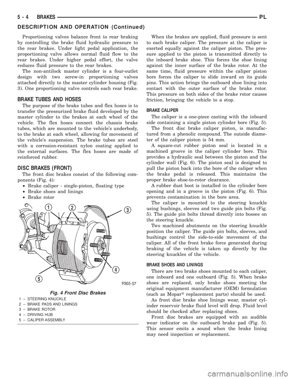
The front disc brakes consist of the following com-
ponents (Fig. 4):
²Brake caliper - single-piston, floating type
²Brake shoes and linings
²Brake rotorWhen the brakes are applied, fluid pressure is sent
to each brake caliper. The pressure at the caliper is
exerted equally against the caliper piston. The pres-
sure applied to the piston is transmitted directly to
the inboard brake shoe. This forces the shoe lining
against the inner surface of the brake rotor. At the
same time, fluid pressure within the caliper piston
bore forces the caliper to slide inward on its guide
pins. This action brings the outboard shoe lining into
contact with the outer surface of the brake rotor.
This pressure on both sides of the brake rotor causes
friction, bringing the vehicle to a stop.
BRAKE CALIPER
The caliper is a one-piece casting with the inboard
side containing a single piston cylinder bore (Fig. 5).
The front disc brake caliper piston, is manufac-
tured from a phenolic compound. The outside diame-
ter of the caliper piston is 54 mm.
A square-cut rubber piston seal is located in a
machined groove in the caliper cylinder bore. This
provides a hydraulic seal between the piston and the
cylinder wall (Fig. 6). The piston seal is designed to
pull the piston back into the bore of the caliper when
the brake pedal is released. This maintains the
proper brake shoe-to-rotor clearance.
A rubber dust boot is installed in the cylinder bore
opening and in a groove in the piston (Fig. 6). This
prevents contamination in the bore area.
The caliper is mounted to the steering knuckle
using bushings, sleeves and two guide pin bolts (Fig.
5). The guide pin bolts thread directly into bosses on
the steering knuckle.
Two machined abutments on the steering knuckle
position the caliper. The guide pin bolts, sleeves, and
bushings control the side-to-side movement of the
caliper. All of the front brake force generated during
braking of the vehicle is taken up directly by the
steering knuckles of the vehicle.
BRAKE SHOES AND LININGS
There are two brake shoes mounted to each caliper,
one inboard and one outboard (Fig. 5). When brake
shoes are replaced, only brake shoes meeting the
original equipment manufacturer (OEM) formulation
(such as Mopartreplacement parts) should be used.
As front disc brake shoe linings wear, master cyl-
inder reservoir brake fluid level will drop. Fluid level
should be checked after replacing shoes.
Front disc brakes are equipped with an audible
wear indicator on the outboard brake pad (Fig. 5).
This sensor emits a sound when the brake lining
may need inspection or replacement.
Fig. 4 Front Disc Brakes
1 ± STEERING KNUCKLE
2 ± BRAKE PADS AND LININGS
3 ± BRAKE ROTOR
4 ± DRIVING HUB
5 ± CALIPER ASSEMBLY
5 - 4 BRAKESPL
DESCRIPTION AND OPERATION (Continued)
Page 87 of 1285
RED BRAKE WARNING LAMP
The red BRAKE warning lamp is located in the
instrument panel cluster and illuminates when a low
brake fluid condition occurs or when the parking
brake lever is applied with the ignition key in the
ON position. In addition, the red BRAKE warning
lamp illuminates when the ignition switch is moved
from the OFF to the ON or CRANK position. This is
done to check the bulb's operation.
Problems with this system will generally be of the
type where the warning lamp fails to turn on when it
should, or remains on when it should not.
The red BRAKE warning lamp LED is supplied
with current anytime the ignition switch is ON. The
bulb is illuminated by completing the ground circuit
using any of the following components:
²the brake fluid level switch located in the mas-
ter cylinder reservoir
²the parking brake switch mounted on the park-
ing brake lever (Fig. 10)
²the ignition switch when the ignition switch is
first moved to the ON or CRANK position
²the mechanical instrument cluster (MIC) (with
ABS)
²the ABS electronic brake distribution (EBD)
The brake fluid level switch is located in the brake
fluid reservoir of the master cylinder assembly (Fig.
1). The purpose of the switch is to provide the driver
with an early warning that the brake fluid level inthe master cylinder reservoir has dropped below an
acceptable level.
As the fluid drops below the minimum level, the
fluid level switch closes and grounds the red BRAKE
warning lamp circuit. This turns on the red BRAKE
warning lamp. At this time, the master cylinder fluid
reservoir must be checked and filled to the full mark
with DOT 3 brake fluid. An abnormal loss of brake
fluid in the master cylinder fluid reservoir could be
caused by a leak in the hydraulic system. The entire
brake hydraulic system should be checked for evi-
dence of a leak.
The red BRAKE warning lamp can be turned on by
the MIC in the case where the ABS is experiencing a
problem where the amber ABS warning lamp needs
to be illuminated and cannot. The MIC will then illu-
minate the red BRAKE warning lamp.
BRAKE LAMP SWITCH
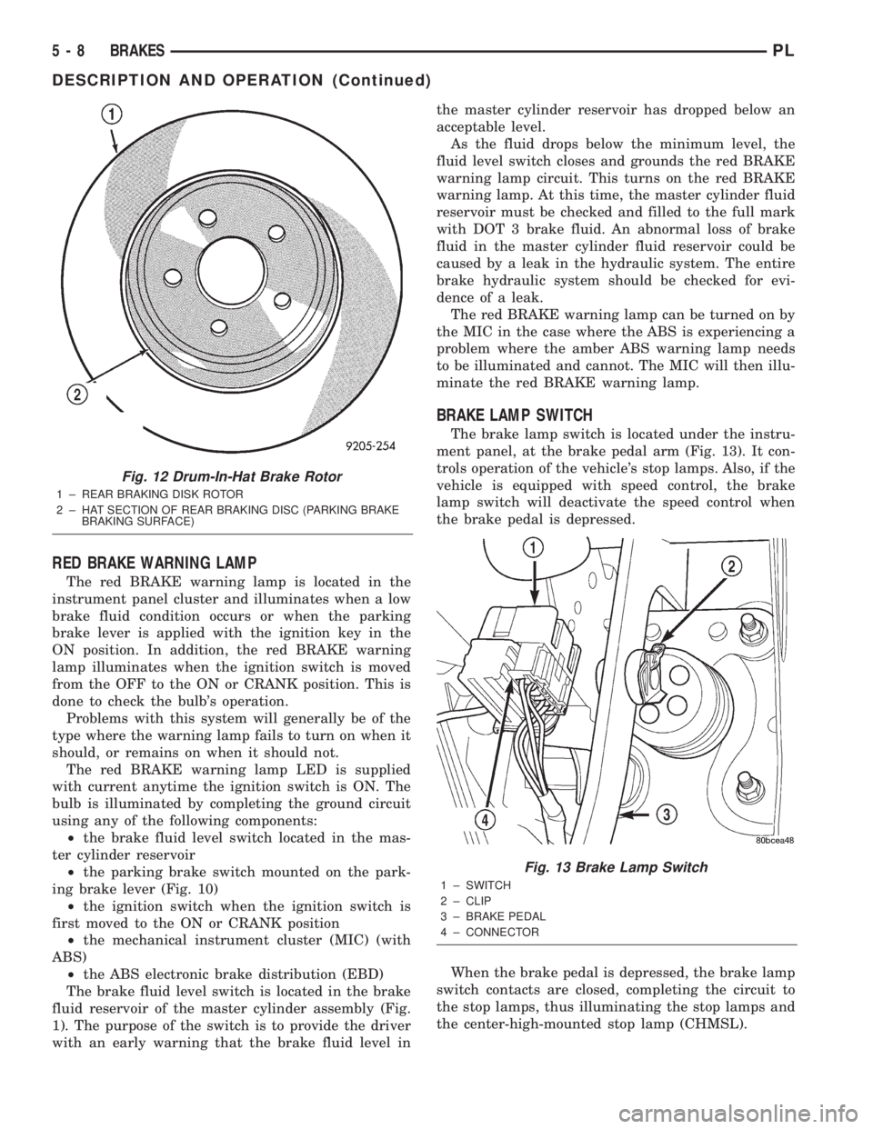
The brake lamp switch is located under the instru-
ment panel, at the brake pedal arm (Fig. 13). It con-
trols operation of the vehicle's stop lamps. Also, if the
vehicle is equipped with speed control, the brake
lamp switch will deactivate the speed control when
the brake pedal is depressed.
When the brake pedal is depressed, the brake lamp
switch contacts are closed, completing the circuit to
the stop lamps, thus illuminating the stop lamps and
the center-high-mounted stop lamp (CHMSL).
Fig. 12 Drum-In-Hat Brake Rotor
1 ± REAR BRAKING DISK ROTOR
2 ± HAT SECTION OF REAR BRAKING DISC (PARKING BRAKE
BRAKING SURFACE)
Fig. 13 Brake Lamp Switch
1 ± SWITCH
2 ± CLIP
3 ± BRAKE PEDAL
4 ± CONNECTOR
5 - 8 BRAKESPL
DESCRIPTION AND OPERATION (Continued)
Page 88 of 1285
DIAGNOSIS AND TESTING
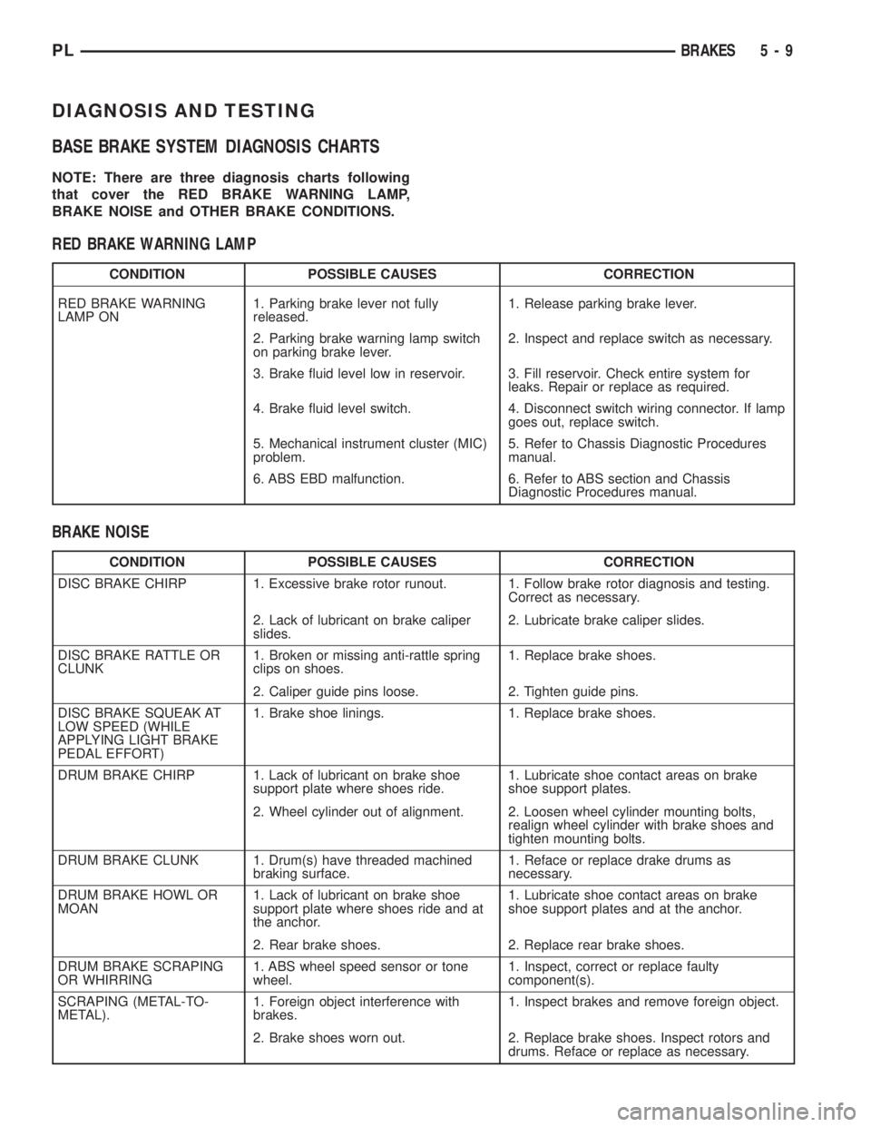
BASE BRAKE SYSTEM DIAGNOSIS CHARTS
NOTE: There are three diagnosis charts following
that cover the RED BRAKE WARNING LAMP,
BRAKE NOISE and OTHER BRAKE CONDITIONS.
RED BRAKE WARNING LAMP
CONDITION POSSIBLE CAUSES CORRECTION
RED BRAKE WARNING
LAMP ON1. Parking brake lever not fully
released.1. Release parking brake lever.
2. Parking brake warning lamp switch
on parking brake lever.2. Inspect and replace switch as necessary.
3. Brake fluid level low in reservoir. 3. Fill reservoir. Check entire system for
leaks. Repair or replace as required.
4. Brake fluid level switch. 4. Disconnect switch wiring connector. If lamp
goes out, replace switch.
5. Mechanical instrument cluster (MIC)
problem.5. Refer to Chassis Diagnostic Procedures
manual.
6. ABS EBD malfunction. 6. Refer to ABS section and Chassis
Diagnostic Procedures manual.
BRAKE NOISE
CONDITION POSSIBLE CAUSES CORRECTION
DISC BRAKE CHIRP 1. Excessive brake rotor runout. 1. Follow brake rotor diagnosis and testing.
Correct as necessary.
2. Lack of lubricant on brake caliper
slides.2. Lubricate brake caliper slides.
DISC BRAKE RATTLE OR
CLUNK1. Broken or missing anti-rattle spring
clips on shoes.1. Replace brake shoes.
2. Caliper guide pins loose. 2. Tighten guide pins.
DISC BRAKE SQUEAK AT
LOW SPEED (WHILE
APPLYING LIGHT BRAKE
PEDAL EFFORT)1. Brake shoe linings. 1. Replace brake shoes.
DRUM BRAKE CHIRP 1. Lack of lubricant on brake shoe
support plate where shoes ride.1. Lubricate shoe contact areas on brake
shoe support plates.
2. Wheel cylinder out of alignment. 2. Loosen wheel cylinder mounting bolts,
realign wheel cylinder with brake shoes and
tighten mounting bolts.
DRUM BRAKE CLUNK 1. Drum(s) have threaded machined
braking surface.1. Reface or replace drake drums as
necessary.
DRUM BRAKE HOWL OR
MOAN1. Lack of lubricant on brake shoe
support plate where shoes ride and at
the anchor.1. Lubricate shoe contact areas on brake
shoe support plates and at the anchor.
2. Rear brake shoes. 2. Replace rear brake shoes.
DRUM BRAKE SCRAPING
OR WHIRRING1. ABS wheel speed sensor or tone
wheel.1. Inspect, correct or replace faulty
component(s).
SCRAPING (METAL-TO-
METAL).1. Foreign object interference with
brakes.1. Inspect brakes and remove foreign object.
2. Brake shoes worn out. 2. Replace brake shoes. Inspect rotors and
drums. Reface or replace as necessary.
PLBRAKES 5 - 9
Page 89 of 1285
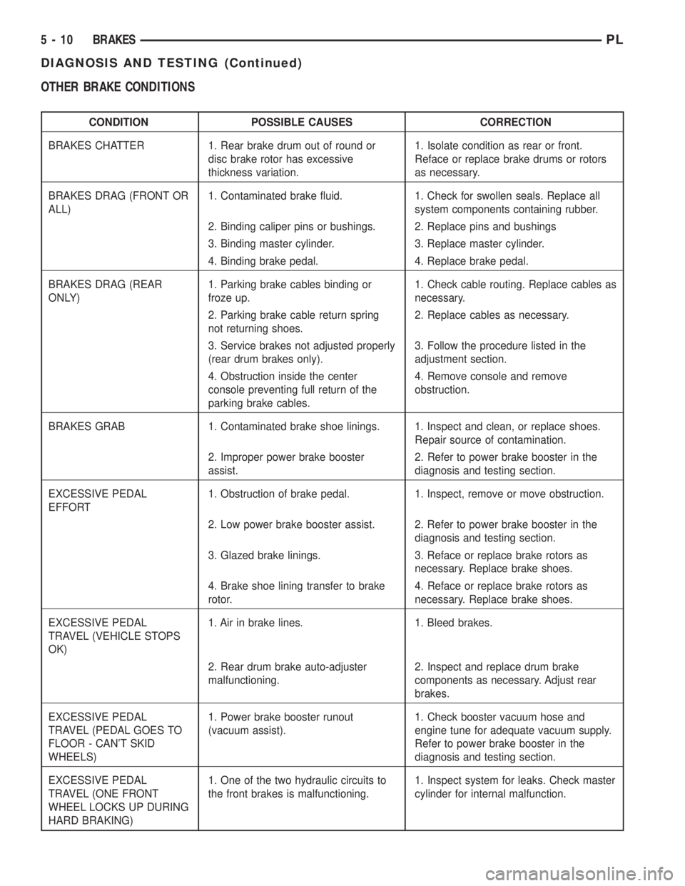
OTHER BRAKE CONDITIONS
CONDITION POSSIBLE CAUSES CORRECTION
BRAKES CHATTER 1. Rear brake drum out of round or
disc brake rotor has excessive
thickness variation.1. Isolate condition as rear or front.
Reface or replace brake drums or rotors
as necessary.
BRAKES DRAG (FRONT OR
ALL)1. Contaminated brake fluid. 1. Check for swollen seals. Replace all
system components containing rubber.
2. Binding caliper pins or bushings. 2. Replace pins and bushings
3. Binding master cylinder. 3. Replace master cylinder.
4. Binding brake pedal. 4. Replace brake pedal.
BRAKES DRAG (REAR
ONLY)1. Parking brake cables binding or
froze up.1. Check cable routing. Replace cables as
necessary.
2. Parking brake cable return spring
not returning shoes.2. Replace cables as necessary.
3. Service brakes not adjusted properly
(rear drum brakes only).3. Follow the procedure listed in the
adjustment section.
4. Obstruction inside the center
console preventing full return of the
parking brake cables.4. Remove console and remove
obstruction.
BRAKES GRAB 1. Contaminated brake shoe linings. 1. Inspect and clean, or replace shoes.
Repair source of contamination.
2. Improper power brake booster
assist.2. Refer to power brake booster in the
diagnosis and testing section.
EXCESSIVE PEDAL
EFFORT1. Obstruction of brake pedal. 1. Inspect, remove or move obstruction.
2. Low power brake booster assist. 2. Refer to power brake booster in the
diagnosis and testing section.
3. Glazed brake linings. 3. Reface or replace brake rotors as
necessary. Replace brake shoes.
4. Brake shoe lining transfer to brake
rotor.4. Reface or replace brake rotors as
necessary. Replace brake shoes.
EXCESSIVE PEDAL
TRAVEL (VEHICLE STOPS
OK)1. Air in brake lines. 1. Bleed brakes.
2. Rear drum brake auto-adjuster
malfunctioning.2. Inspect and replace drum brake
components as necessary. Adjust rear
brakes.
EXCESSIVE PEDAL
TRAVEL (PEDAL GOES TO
FLOOR - CAN'T SKID
WHEELS)1. Power brake booster runout
(vacuum assist).1. Check booster vacuum hose and
engine tune for adequate vacuum supply.
Refer to power brake booster in the
diagnosis and testing section.
EXCESSIVE PEDAL
TRAVEL (ONE FRONT
WHEEL LOCKS UP DURING
HARD BRAKING)1. One of the two hydraulic circuits to
the front brakes is malfunctioning.1. Inspect system for leaks. Check master
cylinder for internal malfunction.
5 - 10 BRAKESPL
DIAGNOSIS AND TESTING (Continued)
Page 95 of 1285
The in-line proportioning valves used on this vehi-
cle require special pressure fittings to test the pro-
portioning valves for proper proportioning valve
function. The pressure fittings are installed before
and after the proportioning valve being tested to ver-
ify proportioning valve is maintaining the required
hydraulic pressure to the rear wheel brake which it
controls.
The testing of proportioning valves for this vehicle,
if equipped with ABS, can be found in the
ANTILOCK BRAKE SYSTEM section.
PROPORTIONING VALVE TEST
The test procedure is the same for either rear pro-
portioning valve. After road testing the vehicle to
determine which wheel skids first, follow the proce-
dure below for testing the suspect proportioning
valve.
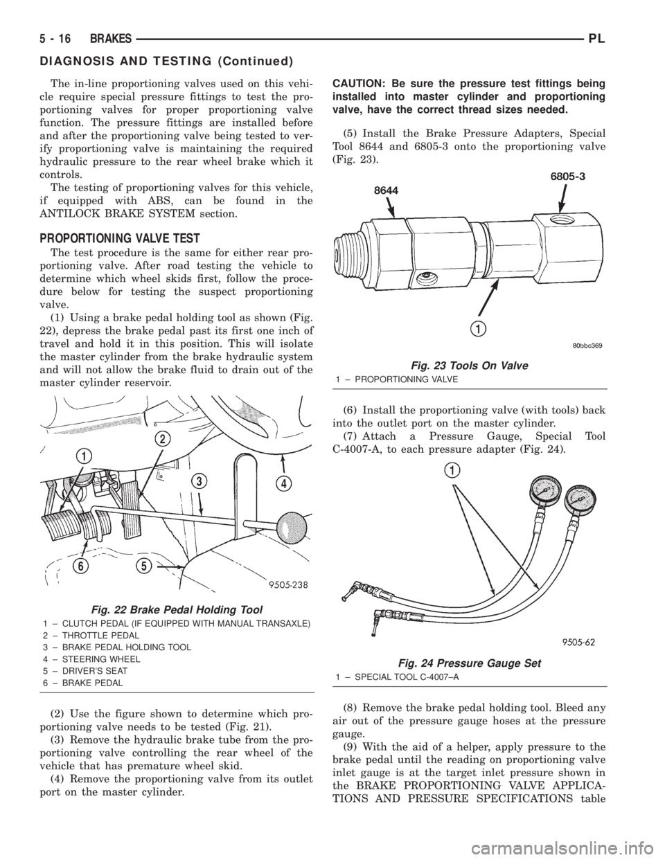
(1) Using a brake pedal holding tool as shown (Fig.
22), depress the brake pedal past its first one inch of
travel and hold it in this position. This will isolate
the master cylinder from the brake hydraulic system
and will not allow the brake fluid to drain out of the
master cylinder reservoir.
(2) Use the figure shown to determine which pro-
portioning valve needs to be tested (Fig. 21).
(3) Remove the hydraulic brake tube from the pro-
portioning valve controlling the rear wheel of the
vehicle that has premature wheel skid.
(4) Remove the proportioning valve from its outlet
port on the master cylinder.CAUTION: Be sure the pressure test fittings being
installed into master cylinder and proportioning
valve, have the correct thread sizes needed.
(5) Install the Brake Pressure Adapters, Special
Tool 8644 and 6805-3 onto the proportioning valve
(Fig. 23).
(6) Install the proportioning valve (with tools) back
into the outlet port on the master cylinder.
(7) Attach a Pressure Gauge, Special Tool
C-4007-A, to each pressure adapter (Fig. 24).
(8) Remove the brake pedal holding tool. Bleed any
air out of the pressure gauge hoses at the pressure
gauge.
(9) With the aid of a helper, apply pressure to the
brake pedal until the reading on proportioning valve
inlet gauge is at the target inlet pressure shown in
the BRAKE PROPORTIONING VALVE APPLICA-
TIONS AND PRESSURE SPECIFICATIONS table
Fig. 22 Brake Pedal Holding Tool
1 ± CLUTCH PEDAL (IF EQUIPPED WITH MANUAL TRANSAXLE)
2 ± THROTTLE PEDAL
3 ± BRAKE PEDAL HOLDING TOOL
4 ± STEERING WHEEL
5 ± DRIVER'S SEAT
6 ± BRAKE PEDAL
Fig. 23 Tools On Valve
1 ± PROPORTIONING VALVE
Fig. 24 Pressure Gauge Set
1 ± SPECIAL TOOL C-4007±A
5 - 16 BRAKESPL
DIAGNOSIS AND TESTING (Continued)
Page 96 of 1285
following this procedure. If the inlet gauge pressure
overshoots its target pressure when the pedal is
depressed, release the brake pedal, relieving the
pressure in the system, before reapplying the pedal
to reach the target pressure at the inlet gauge. This
is necessary to get an accurate reading of the outlet
pressure.
(10) Once inlet pressure has been achieved, check
the pressure reading on the proportioning valve out-
let gauge. If the proportioning valve outlet pressure
does not agree with value shown in the table, replace
the proportioning valve. If proportioning valve is
within pressure specifications, the valve is good and
does not require replacement.(11)Reinstall the brake holding tool on the brake
pedal and remove the test equipment from the vehicle.
(12) Remove the tools from the proportioning
valve.
(13) Install the proportioning valve in the master
cylinder and hand tighten until the proportioning
valve is fully installed and its O-ring seal is seated
into the master cylinder. Torque the proportioning
valve to 40 N´m (30 ft. lbs.).
(14) Install the brake tube on the proportioning
valve. Torque the tube nut to 17 N´m (145 in. lbs.).
(15) Bleed the affected brake line. See BASE
BRAKE BLEEDING in this section of this service
manual group.
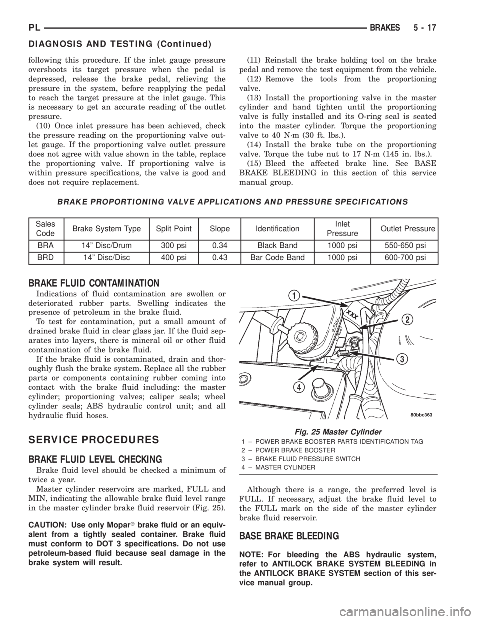
BRAKE PROPORTIONING VALVE APPLICATIONS AND PRESSURE SPECIFICATIONS
Sales
CodeBrake System Type Split Point Slope IdentificationInlet
PressureOutlet Pressure
BRA 14º Disc/Drum 300 psi 0.34 Black Band 1000 psi 550-650 psi
BRD 14º Disc/Disc 400 psi 0.43 Bar Code Band 1000 psi 600-700 psi
BRAKE FLUID CONTAMINATION
Indications of fluid contamination are swollen or
deteriorated rubber parts. Swelling indicates the
presence of petroleum in the brake fluid.
To test for contamination, put a small amount of
drained brake fluid in clear glass jar. If the fluid sep-
arates into layers, there is mineral oil or other fluid
contamination of the brake fluid.
If the brake fluid is contaminated, drain and thor-
oughly flush the brake system. Replace all the rubber
parts or components containing rubber coming into
contact with the brake fluid including: the master
cylinder; proportioning valves; caliper seals; wheel
cylinder seals; ABS hydraulic control unit; and all
hydraulic fluid hoses.
SERVICE PROCEDURES
BRAKE FLUID LEVEL CHECKING
Brake fluid level should be checked a minimum of
twice a year.
Master cylinder reservoirs are marked, FULL and
MIN, indicating the allowable brake fluid level range
in the master cylinder brake fluid reservoir (Fig. 25).
CAUTION: Use only MoparTbrake fluid or an equiv-
alent from a tightly sealed container. Brake fluid
must conform to DOT 3 specifications. Do not use
petroleum-based fluid because seal damage in the
brake system will result.Although there is a range, the preferred level is
FULL. If necessary, adjust the brake fluid level to
the FULL mark on the side of the master cylinder
brake fluid reservoir.
BASE BRAKE BLEEDING
NOTE: For bleeding the ABS hydraulic system,
refer to ANTILOCK BRAKE SYSTEM BLEEDING in
the ANTILOCK BRAKE SYSTEM section of this ser-
vice manual group.
Fig. 25 Master Cylinder
1 ± POWER BRAKE BOOSTER PARTS IDENTIFICATION TAG
2 ± POWER BRAKE BOOSTER
3 ± BRAKE FLUID PRESSURE SWITCH
4 ± MASTER CYLINDER
PLBRAKES 5 - 17
DIAGNOSIS AND TESTING (Continued)
Page 97 of 1285
CAUTION: Before removing the master cylinder
cap, wipe it clean to prevent dirt and other foreign
matter from dropping into the master cylinder res-
ervoir.
CAUTION: Use only MoparTbrake fluid or an equiv-
alent from a fresh, tightly sealed container. Brake
fluid must conform to DOT 3 specifications.
Do not pump the brake pedal at any time while
having a bleeder screw open during the bleeding pro-
cess. This will only increase the amount of air in the
system and make additional bleeding necessary.
Do not allow the master cylinder reservoir to run
out of brake fluid while bleeding the system. An
empty reservoir will allow additional air into the
brake system. Check the fluid level frequently and
add fluid as needed.
The following wheel circuit sequence for bleeding
the brake hydraulic system should be used to ensure
adequate removal of all trapped air from the hydrau-
lic system.
²Left rear wheel
²Right front wheel
²Right rear wheel
²Left front wheel
MANUAL BLEEDING
NOTE: To bleed the brakes manually, the aid of a
helper will be required.
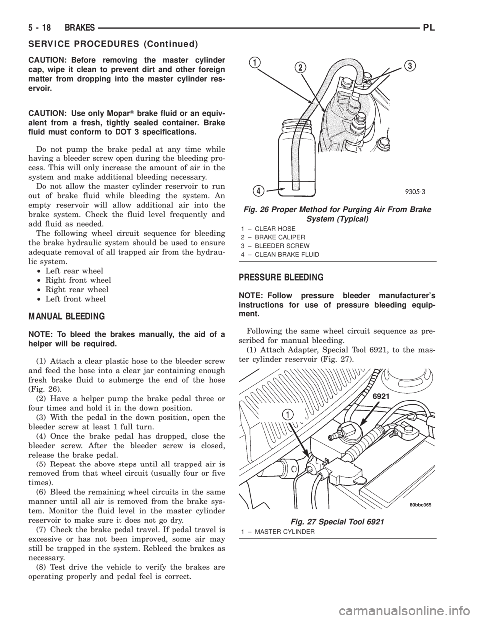
(1) Attach a clear plastic hose to the bleeder screw
and feed the hose into a clear jar containing enough
fresh brake fluid to submerge the end of the hose
(Fig. 26).
(2) Have a helper pump the brake pedal three or
four times and hold it in the down position.
(3) With the pedal in the down position, open the
bleeder screw at least 1 full turn.
(4) Once the brake pedal has dropped, close the
bleeder screw. After the bleeder screw is closed,
release the brake pedal.
(5) Repeat the above steps until all trapped air is
removed from that wheel circuit (usually four or five
times).
(6) Bleed the remaining wheel circuits in the same
manner until all air is removed from the brake sys-
tem. Monitor the fluid level in the master cylinder
reservoir to make sure it does not go dry.
(7) Check the brake pedal travel. If pedal travel is
excessive or has not been improved, some air may
still be trapped in the system. Rebleed the brakes as
necessary.
(8) Test drive the vehicle to verify the brakes are
operating properly and pedal feel is correct.
PRESSURE BLEEDING
NOTE: Follow pressure bleeder manufacturer's
instructions for use of pressure bleeding equip-
ment.
Following the same wheel circuit sequence as pre-
scribed for manual bleeding.
(1) Attach Adapter, Special Tool 6921, to the mas-
ter cylinder reservoir (Fig. 27).
Fig. 26 Proper Method for Purging Air From Brake
System (Typical)
1 ± CLEAR HOSE
2 ± BRAKE CALIPER
3 ± BLEEDER SCREW
4 ± CLEAN BRAKE FLUID
Fig. 27 Special Tool 6921
1 ± MASTER CYLINDER
5 - 18 BRAKESPL
SERVICE PROCEDURES (Continued)
Page 98 of 1285
(2) Attach Bleeder Tank, Special Tool C-3496-B, or
an equivalent, to the adapter on the master cylinder.
(3) Attach a clear plastic hose to the bleeder screw
and feed the hose into a clear jar containing enough
fresh brake fluid to submerge the end of the hose
(Fig. 26).
(4) Open the bleeder screw at least one full turn or
more to obtain a steady stream of brake fluid.
(5) After approximately 4±8 ounces of fluid have
been bled through the brake circuit and an air-free
flow is maintained in the clear plastic hose and jar,
close the bleeder screw.
(6) Repeat this procedure at all the remaining
bleeder screws.
(7) Check the brake pedal travel. If pedal travel is
excessive or has not been improved, some air may
still be trapped in the system. Rebleed the brakes as
necessary.
(8) Test drive the vehicle to verify the brakes are
operating properly and pedal feel is correct.
MASTER CYLINDER BLEEDING
(1) Clamp the master cylinder in a vise.
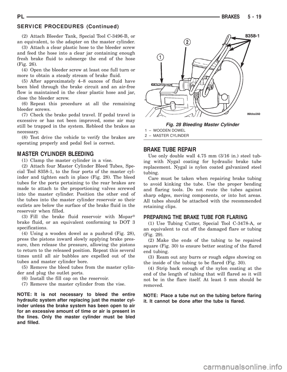
(2) Attach four Master Cylinder Bleed Tubes, Spe-
cial Tool 8358-1, to the four ports of the master cyl-
inder and tighten each in place (Fig. 28). The bleed
tubes for the ports pertaining to the rear brakes are
made to attach to the proportioning valves screwed
into the master cylinder. Position the other end of
the tubes into the master cylinder reservoir so their
outlets are below the surface of the brake fluid in the
reservoir when filled.
(3) Fill the brake fluid reservoir with Mopart
brake fluid, or an equivalent conforming to DOT 3
specifications.
(4) Using a wooden dowel as a pushrod (Fig. 28),
press the pistons inward slowly applying brake pres-
sure, then release the pressure, allowing the pistons
to return to the released position. Repeat this several
times until all air bubbles are expelled out of the
tubes and master cylinder bore.
(5) Remove the bleed tubes from the master cylin-
der and plug the outlet ports.
(6) Install the fill cap on the reservoir.
(7) Remove the master cylinder from the vise.
NOTE: It is not necessary to bleed the entire
hydraulic system after replacing just the master cyl-
inder unless the brake system has been open to air
for an excessive amount of time or air is present in
the lines. Only the master cylinder must be bled
and filled.
BRAKE TUBE REPAIR
Use only double wall 4.75 mm (3/16 in.) steel tub-
ing with Nygal coating for hydraulic brake tube
replacement. Nygal is nylon coated galvanized steel
tubing.
Care must be taken when repairing brake tubing
to avoid kinking the tube. Use the proper bending
and flaring tools. Do not route the tubes against
sharp edges, moving components, or into hot areas.
All tubes should be attached with the recommended
retaining clips.
PREPARING THE BRAKE TUBE FOR FLARING
(1) Use Tubing Cutter, Special Tool C-3478-A, or
an equivalent to cut off the damaged flare or tubing
(Fig. 29).
(2) Make the ends of the tubing to be repaired
square (Fig. 30) to ensure better seating of the flared
end tubing.
(3) Ream out any burrs or rough edges showing on
the inside of the tubing to be flared (Fig. 30).
(4) Strip back enough of the nylon coating at the
end of the length of tubing that will flared so it will
not be in the flare itself. At least 5 mm should be
removed.
NOTE: Place a tube nut on the tubing before flaring
it. It cannot be done after the tube is flared.
Fig. 28 Bleeding Master Cylinder
1 ± WOODEN DOWEL
2 ± MASTER CYLINDER
PLBRAKES 5 - 19
SERVICE PROCEDURES (Continued)