2000 DODGE NEON low beam
[x] Cancel search: low beamPage 31 of 1285
with the notch formed in the side of the ball joint
stud.
(4) If the right lower control arm has been ser-
viced, install the engine torque strut (Fig. 16). Follow
the procedure described in the ENGINE service man-
ual group to properly align and tighten the torque
strut.
(5) Install a new ball joint stud pinch bolt and nut
(Fig. 15). Tighten the nut to a torque of 95 N´m (70
ft. lbs.).
(6) Rotate the forward ends of the stabilizer bar
into mounting position.
(7) Install both stabilizer bar links back on vehicle
(Fig. 14). Start each stabilizer bar link bolt with
bushing from the bottom, through the stabilizer bar,
inner link bushings, lower control arm, and into the
upper retainer/nut and bushing (Fig. 1). Do not fully
tighten the link assemblies at this time.
(8) Lower the vehicle to ground level.
NOTE: It may be necessary to put the vehicle on a
platform hoist or alignment rack to gain access to
the stabilizer bar mounting bolts with the vehicle at
curb height.
(9) Tighten each stabilizer bar link by holding the
upper retainer/nut with a wrench and turning the
link bolt. Tighten each link bolt to a torque of 23
N´m (200 in. lbs.).
(10) If previously loosened, tighten the stabilizer
bar cushion retainer bolts to a torque of 28 N´m (250
in. lbs.).
STABILIZER BAR (FRONT)
NOTE: Before proceeding with this procedure,
review SERVICE WARNINGS AND CAUTIONS at the
beginning of REMOVAL AND INSTALLATION in this
section.
REMOVAL
(1) Raise the vehicle. Refer to HOISTING in the
LUBRICATION AND MAINTENANCE group for the
proper lifting procedure.
(2) Remove both stabilizer bar links from the vehi-
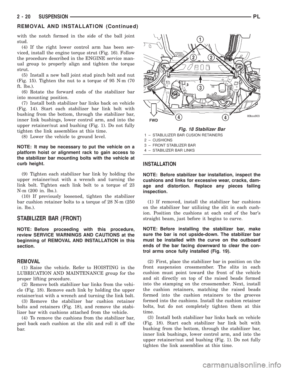
cle (Fig. 18). Remove each link by holding the upper
retainer/nut with a wrench and turning the link bolt.
(3) Remove the stabilizer bar cushion retainer
bolts and retainers (Fig. 18), and remove the stabi-
lizer bar with cushions attached from the vehicle.
(4) To remove the cushions from the stabilizer bar,
peel back each cushion at the slit and roll it off the
bar.
INSTALLATION
NOTE: Before stabilizer bar installation, inspect the
cushions and links for excessive wear, cracks, dam-
age and distortion. Replace any pieces failing
inspection.
(1) If removed, install the stabilizer bar cushions
on the stabilizer bar utilizing the slit in each cush-
ion. Position the cushions at each end of the bar's
straight beam, just before it begins to curve.
NOTE: Before installing the stabilizer bar, make
sure the bar is not upside-down. The stabilizer bar
must be installed with the curve on the outboard
ends of the bar facing downward to clear the con-
trol arms once fully installed (Fig. 19).
(2) First, place the stabilizer bar in position on the
front suspension crossmember. The slits in each
cushion must point toward the front of the vehicle
and sit directly on top of the raised beads formed
into the stamping on the crossmember. Next, install
the cushion retainers, matching the raised beads
formed into the cushion retainers to the grooves
formed into the cushions. Install the cushion retainer
bolts, but do not completely tighten them at this
time.
(3) Install both stabilizer bar links back on vehicle
(Fig. 18). Start each stabilizer bar link bolt with
bushing from the bottom, through the stabilizer bar,
inner link bushings, lower control arm, and into the
upper retainer/nut and bushing (Fig. 1). Do not fully
tighten the link assemblies at this time.
Fig. 18 Stabilizer Bar
1 ± STABLILIZER BAR CUSION RETAINERS
2 ± CUSHIONS
3 ± FRONT STABLIZER BAR
4 ± STABILIZER BAR LINKS
2 - 20 SUSPENSIONPL
REMOVAL AND INSTALLATION (Continued)
Page 194 of 1285
WATER PUMP DIAGNOSIS
A quick flow test to tell whether or not the pump is
working is to see if the heater warms properly. A
defective pump will not be able to circulate heated
coolant through the long heater hose.
Another flow test to help determine pump opera-
tion:
WARNING: DO NOT remove radiator cap if the cool-
ing system is hot or under pressure.
(1) Remove cooling system pressure cap.
(2) Remove a small amount of coolant from the
system.
(3) Start the engine and warm up until thermostat
opens.
(4) With the thermostat open and coolant level low,
visually inspect for coolant flow. If flow is present,
the water pump is pumping coolant through the sys-
tem.
COOLING SYSTEM FLOW CHECK
To determine whether coolant is flowing through
the cooling system, use the following procedures:
(1) If engine is cold, idle engine until normal oper-
ating temperature is reached. Then feel the upper
radiator hose. If it is hot, coolant is circulating.
WARNING: DO NOT REMOVE THE COOLING SYS-
TEM PRESSURE CAP WITH THE SYSTEM HOT AND
UNDER PRESSURE BECAUSE SERIOUS BURNS
FROM COOLANT CAN OCCUR.
(2) Remove pressure cap when engine is cold,
remove small amount of coolant Idle engine until
thermostat opens, you should observe coolant flow
while looking down the filler neck. Once flow is
detected install the pressure cap.
ELECTRIC FAN MOTOR TEST
Refer to Powertrain Diagnostic Manual for proce-
dure.
COOLANT CONCENTRATION TESTING
Coolant concentration should be checked when any
additional coolant was added to system or after a
coolant drain, flush and refill. The coolant mixture
offers optimum engine cooling and protection against
corrosion when mixed to a freeze point of -37ÉC
(-34ÉF) to -59ÉC (-50ÉF). The use of a hydrometer or a
refractometer can be used to test coolant concentra-
tion.
A hydrometer will test the amount of glycol in a
mixture by measuring the specific gravity of the mix-
ture. The higher the concentration of ethylene glycol,
the larger the number of balls that will float, andhigher the freeze protection (up to a maximum of
70% by volume glycol).
A refractometer will test the amount of glycol in a
coolant mixture by measuring the amount a beam of
light bends as it passes through the fluid.
Some coolant manufactures use other types of gly-
cols into their coolant formulations. Propylene glycol
is the most common new coolant. However, propylene
glycol based coolants do not provide the same freez-
ing protection and corrosion protection and is only
recommended for limited usage. Refer to appropriate
Technical Service Bulletin(s) regarding use of propy-
lene glycol based coolants.
CAUTION: Do not mix types of coolantÐcorrosion
protection will be severely reduced.
Because ethylene glycol and propylene glycol do
not have the same specific gravities, the use of a
hydrometer will be inaccurate. Therefore, Special
Tool 8286 refractometer, is recommended when test-
ing either ethylene or propylene glycol coolants.
TESTING COOLING SYSTEM FOR LEAKS
The system should be full. With the engine not
running, wipe the filler neck sealing seat clean.
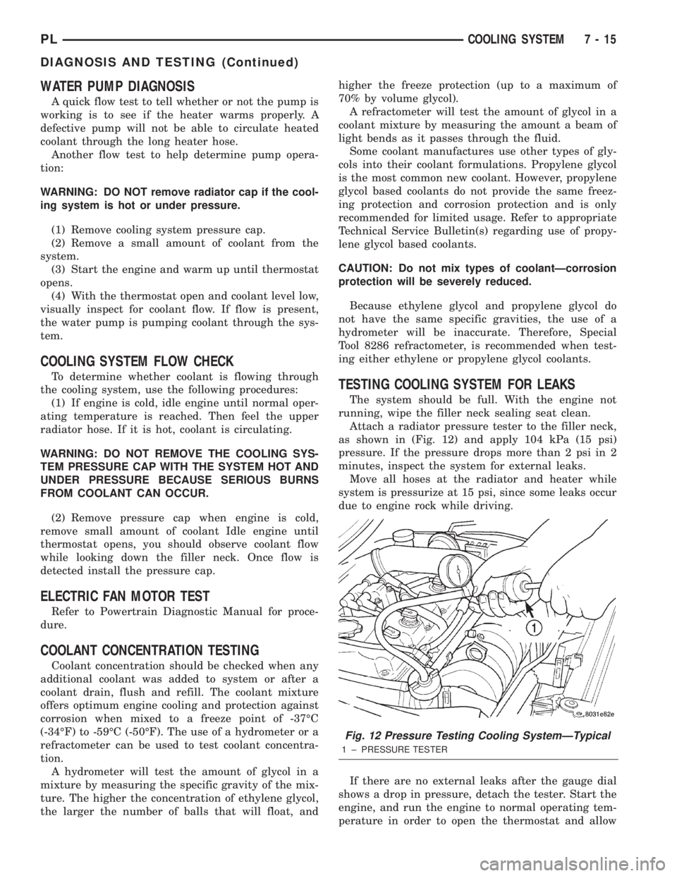
Attach a radiator pressure tester to the filler neck,
as shown in (Fig. 12) and apply 104 kPa (15 psi)
pressure. If the pressure drops more than 2 psi in 2
minutes, inspect the system for external leaks.
Move all hoses at the radiator and heater while
system is pressurize at 15 psi, since some leaks occur
due to engine rock while driving.
If there are no external leaks after the gauge dial
shows a drop in pressure, detach the tester. Start the
engine, and run the engine to normal operating tem-
perature in order to open the thermostat and allow
Fig. 12 Pressure Testing Cooling SystemÐTypical
1 ± PRESSURE TESTER
PLCOOLING SYSTEM 7 - 15
DIAGNOSIS AND TESTING (Continued)
Page 249 of 1285
DESCRIPTION AND OPERATION
HEADLAMP SWITCH
The headlamp switch is part of the Multi-Function
Switch. Refer to Group 8J, Turn Signal and Flasher
for the Multi-Function Switch Test, Removal and
Installation procedures.
INSTRUMENT CLUSTER
There are two conventional instrument cluster
assemblies available. The clusters electronically drive
the speedometer, odometer, gauges, and tachometer
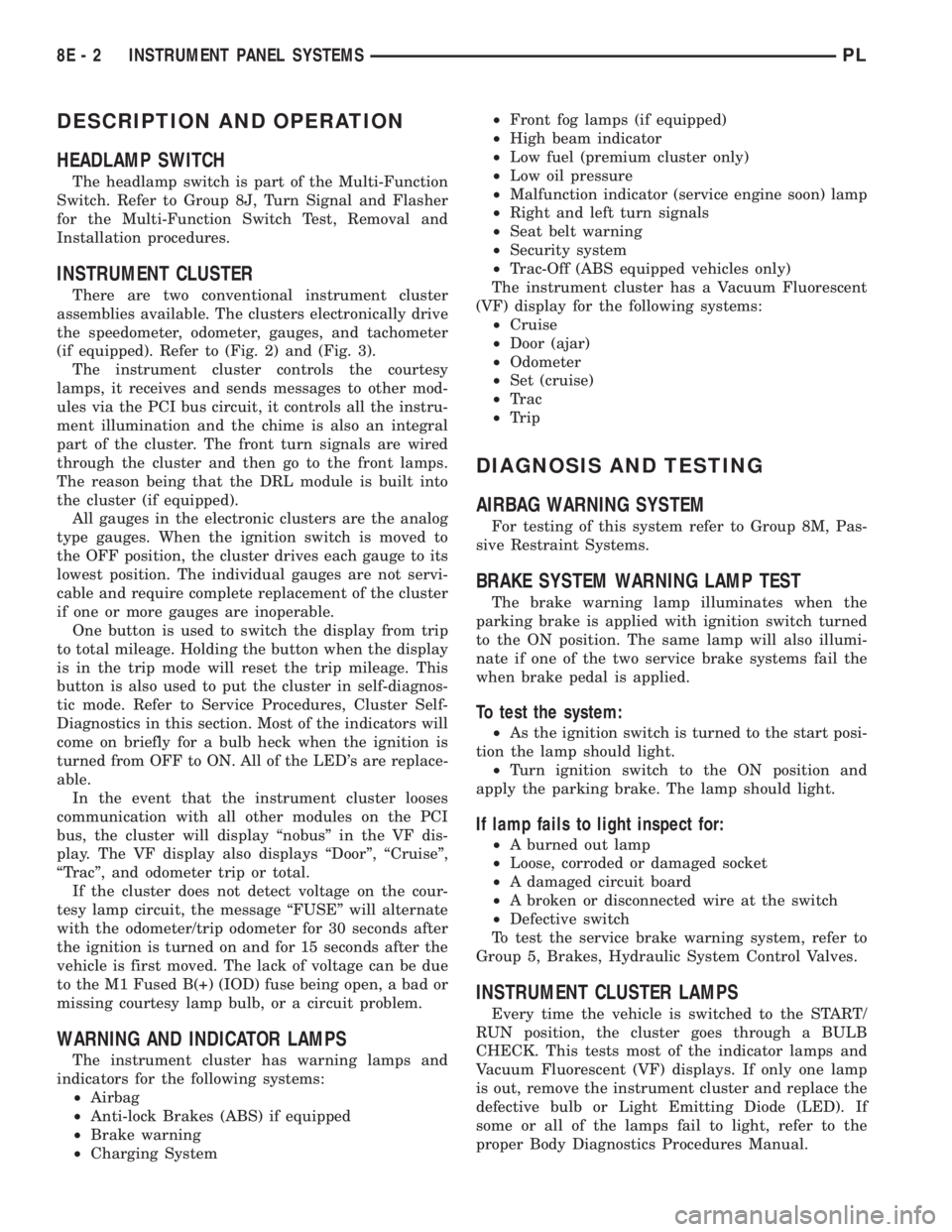
(if equipped). Refer to (Fig. 2) and (Fig. 3).
The instrument cluster controls the courtesy
lamps, it receives and sends messages to other mod-
ules via the PCI bus circuit, it controls all the instru-
ment illumination and the chime is also an integral
part of the cluster. The front turn signals are wired
through the cluster and then go to the front lamps.
The reason being that the DRL module is built into
the cluster (if equipped).
All gauges in the electronic clusters are the analog
type gauges. When the ignition switch is moved to
the OFF position, the cluster drives each gauge to its
lowest position. The individual gauges are not servi-
cable and require complete replacement of the cluster
if one or more gauges are inoperable.
One button is used to switch the display from trip
to total mileage. Holding the button when the display
is in the trip mode will reset the trip mileage. This
button is also used to put the cluster in self-diagnos-
tic mode. Refer to Service Procedures, Cluster Self-
Diagnostics in this section. Most of the indicators will
come on briefly for a bulb heck when the ignition is
turned from OFF to ON. All of the LED's are replace-
able.
In the event that the instrument cluster looses
communication with all other modules on the PCI
bus, the cluster will display ªnobusº in the VF dis-
play. The VF display also displays ªDoorº, ªCruiseº,
ªTracº, and odometer trip or total.
If the cluster does not detect voltage on the cour-
tesy lamp circuit, the message ªFUSEº will alternate
with the odometer/trip odometer for 30 seconds after
the ignition is turned on and for 15 seconds after the
vehicle is first moved. The lack of voltage can be due
to the M1 Fused B(+) (IOD) fuse being open, a bad or
missing courtesy lamp bulb, or a circuit problem.
WARNING AND INDICATOR LAMPS
The instrument cluster has warning lamps and
indicators for the following systems:
²Airbag
²Anti-lock Brakes (ABS) if equipped
²Brake warning
²Charging System²Front fog lamps (if equipped)
²High beam indicator
²Low fuel (premium cluster only)
²Low oil pressure
²Malfunction indicator (service engine soon) lamp
²Right and left turn signals
²Seat belt warning
²Security system
²Trac-Off (ABS equipped vehicles only)
The instrument cluster has a Vacuum Fluorescent
(VF) display for the following systems:
²Cruise
²Door (ajar)
²Odometer
²Set (cruise)
²Trac
²Trip
DIAGNOSIS AND TESTING
AIRBAG WARNING SYSTEM
For testing of this system refer to Group 8M, Pas-
sive Restraint Systems.
BRAKE SYSTEM WARNING LAMP TEST
The brake warning lamp illuminates when the
parking brake is applied with ignition switch turned
to the ON position. The same lamp will also illumi-
nate if one of the two service brake systems fail the
when brake pedal is applied.
To test the system:
²As the ignition switch is turned to the start posi-
tion the lamp should light.
²Turn ignition switch to the ON position and
apply the parking brake. The lamp should light.
If lamp fails to light inspect for:
²A burned out lamp
²Loose, corroded or damaged socket
²A damaged circuit board
²A broken or disconnected wire at the switch
²Defective switch
To test the service brake warning system, refer to
Group 5, Brakes, Hydraulic System Control Valves.
INSTRUMENT CLUSTER LAMPS
Every time the vehicle is switched to the START/
RUN position, the cluster goes through a BULB
CHECK. This tests most of the indicator lamps and
Vacuum Fluorescent (VF) displays. If only one lamp
is out, remove the instrument cluster and replace the
defective bulb or Light Emitting Diode (LED). If
some or all of the lamps fail to light, refer to the
proper Body Diagnostics Procedures Manual.
8E - 2 INSTRUMENT PANEL SYSTEMSPL
Page 250 of 1285
To diagnose the cluster lamps first place the clus-
ter in self-diagnostic mode. With the ignition switch
in the off position, press the trip odometer reset but-
ton down. Simultaneously turn the ignition key to
the ON position and release the trip reset button. All
the indicator lamps and VF displays should illumi-
nate except for the fog lamp, turn signal, and high
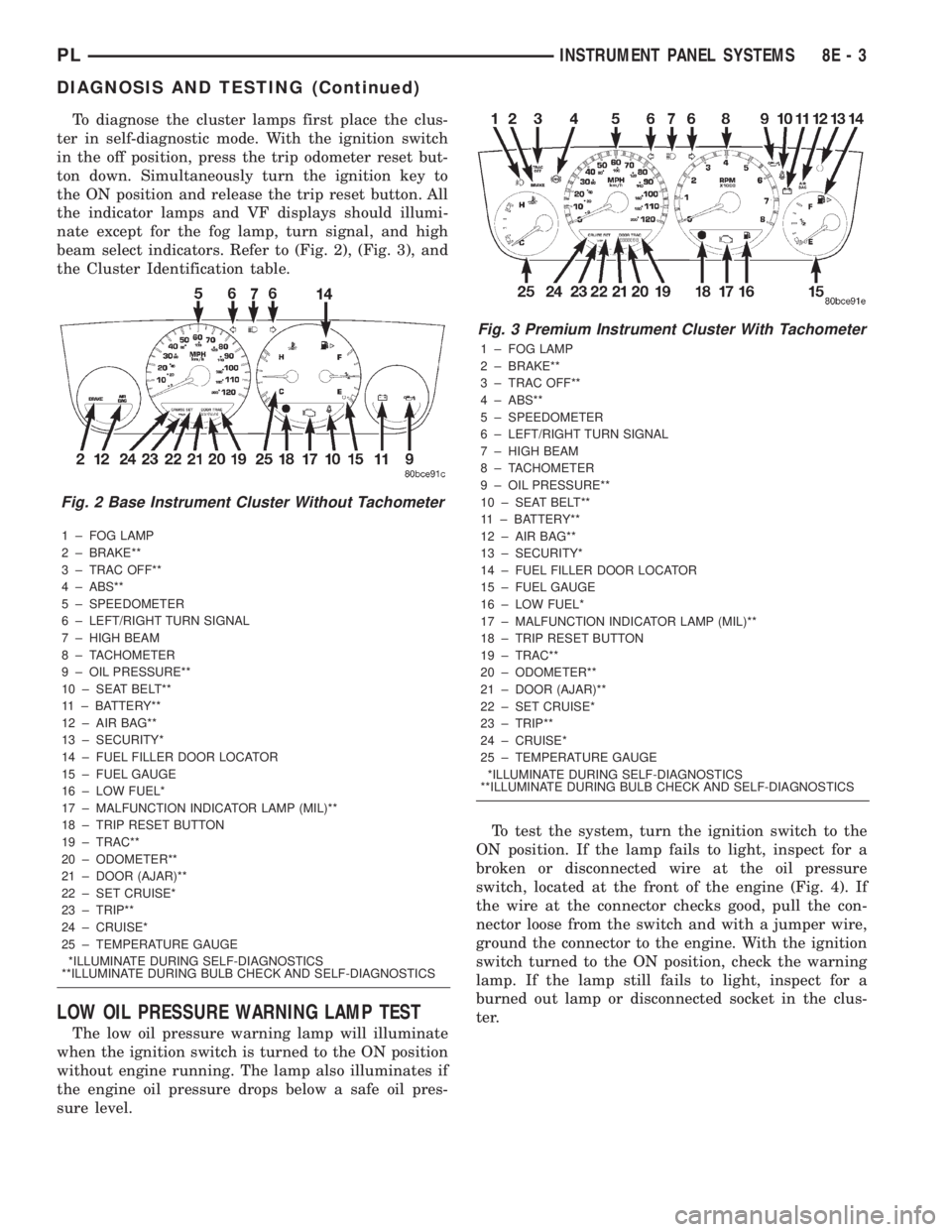
beam select indicators. Refer to (Fig. 2), (Fig. 3), and
the Cluster Identification table.
1 ± FOG LAMP
2 ± BRAKE**
3 ± TRAC OFF**
4 ± ABS**
5 ± SPEEDOMETER
6 ± LEFT/RIGHT TURN SIGNAL
7 ± HIGH BEAM
8 ± TACHOMETER
9 ± OIL PRESSURE**
10 ± SEAT BELT**
11 ± BATTERY**
12 ± AIR BAG**
13 ± SECURITY*
14 ± FUEL FILLER DOOR LOCATOR
15 ± FUEL GAUGE
16 ± LOW FUEL*
17 ± MALFUNCTION INDICATOR LAMP (MIL)**
18 ± TRIP RESET BUTTON
19 ± TRAC**
20 ± ODOMETER**
21 ± DOOR (AJAR)**
22 ± SET CRUISE*
23 ± TRIP**
24 ± CRUISE*
25 ± TEMPERATURE GAUGE
*ILLUMINATE DURING SELF-DIAGNOSTICS
**ILLUMINATE DURING BULB CHECK AND SELF-DIAGNOSTICS
LOW OIL PRESSURE WARNING LAMP TEST
The low oil pressure warning lamp will illuminate
when the ignition switch is turned to the ON position
without engine running. The lamp also illuminates if
the engine oil pressure drops below a safe oil pres-
sure level.To test the system, turn the ignition switch to the
ON position. If the lamp fails to light, inspect for a
broken or disconnected wire at the oil pressure
switch, located at the front of the engine (Fig. 4). If
the wire at the connector checks good, pull the con-
nector loose from the switch and with a jumper wire,
ground the connector to the engine. With the ignition
switch turned to the ON position, check the warning
lamp. If the lamp still fails to light, inspect for a
burned out lamp or disconnected socket in the clus-
ter.
Fig. 2 Base Instrument Cluster Without Tachometer
Fig. 3 Premium Instrument Cluster With Tachometer
1 ± FOG LAMP
2 ± BRAKE**
3 ± TRAC OFF**
4 ± ABS**
5 ± SPEEDOMETER
6 ± LEFT/RIGHT TURN SIGNAL
7 ± HIGH BEAM
8 ± TACHOMETER
9 ± OIL PRESSURE**
10 ± SEAT BELT**
11 ± BATTERY**
12 ± AIR BAG**
13 ± SECURITY*
14 ± FUEL FILLER DOOR LOCATOR
15 ± FUEL GAUGE
16 ± LOW FUEL*
17 ± MALFUNCTION INDICATOR LAMP (MIL)**
18 ± TRIP RESET BUTTON
19 ± TRAC**
20 ± ODOMETER**
21 ± DOOR (AJAR)**
22 ± SET CRUISE*
23 ± TRIP**
24 ± CRUISE*
25 ± TEMPERATURE GAUGE
*ILLUMINATE DURING SELF-DIAGNOSTICS
**ILLUMINATE DURING BULB CHECK AND SELF-DIAGNOSTICS
PLINSTRUMENT PANEL SYSTEMS 8E - 3
DIAGNOSIS AND TESTING (Continued)
Page 251 of 1285
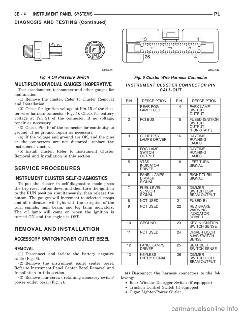
MULTIPLE/INDIVIDUAL GAUGES INOPERATIVE
Test speedometer, tachometer and other gauges for
malfunction:
(1) Remove the cluster. Refer to Cluster Removal
and Installation.
(2) Check for ignition voltage at Pin 15 of the clus-
ter wire harness connector (Fig. 5). Check for battery
voltage at Pin 21 of the connector. If no voltage,
repair as necessary.
(3) Check Pin 10 of the connector for continuity to
ground. If no ground, repair as necessary.
(4) If the voltage and ground are OK, and the pins
or the connectors are not distorted, replace the
instrument cluster.
(5) Install cluster. Refer to Instrument Cluster
Removal and Installation in this section.
SERVICE PROCEDURES
INSTRUMENT CLUSTER SELF-DIAGNOSTICS
To put the cluster in self-diagnostics mode press
the trip reset button down and then turn the ignition
to the RUN position simultaneously, then release the
button. The gauges will increment to selected stoops
and all indicators will light with the exception of the
turn signals, high beam, and fog lamp indicators.
The oil lamp will come on when the ignition is
turned ON and the engine is OFF.
REMOVAL AND INSTALLATION
ACCESSORY SWITCH/POWER OUTLET BEZEL
REMOVAL
(1) Disconnect and isolate the battery negative
cable (Fig. 6).
(2) Remove the instrument panel center bezel.
Refer to Instrument Panel Center Bezel Removal and
Installation in this section.
(3) Remove four screws retaining accessory switch/
power outlet bezel (Fig. 7).(4) Disconnect the harness connectors to the fol-
lowing:
²Rear Window Defogger Switch (if equipped)
²Traction Control Switch (if equipped)
²Cigar Lighter/Power Outlet
Fig. 5 Cluster Wire Harness Connector
INSTRUMENT CLUSTER CONNECTOR PIN
CALL-OUT
PIN DESCRIPTION PIN DESCRIPTION
1 REAR FOG
LAMP FEED14 PARK LAMP
SWITCH
OUTPUT
2 PCI BUS 15 FUSED IGNITION
SWITCH
OUTPUT
(RUN-START)
3 COURTESY
LAMPS DRIVER16 DAYTIME
RUNNING
LAMPS
4 FOG LAMP
SWITCH
OUTPUT17 DAYTIME
RUNNING
LAMPS
5 VTSS
INDICATOR
DRIVER18 LEFT TURN
SIGNAL
6 PANEL LAMPS
DIMMER
SIGNAL19 RIGHT TURN
SIGNAL
7 FUEL LEVEL
SENSOR
SIGNAL20 DIMMER
SWITCH LOW
BEAM OUTPUT
8 NOT USED 21 FUSED B+
9 NOT USED 22 RED BRAKE
WARNING
INDICATOR
DRIVER
10 GROUND 23 KEY-IN IGNITION
SWITCH SENSE
11 NOT USED 24 DRIVER DOOR
AJAR SWITCH
SENSE
12 PANEL LAMPS
DRIVER25 SEAT BELT
SWITCH SENSE
13 KEYLESS
ENTRY SIGNAL26 DIMMER
SWITCH HIGH
BEAM OUTPUT
Fig. 4 Oil Pressure Switch
8E - 4 INSTRUMENT PANEL SYSTEMSPL
DIAGNOSIS AND TESTING (Continued)
Page 254 of 1285

INSTRUMENT CLUSTER LAMPS
WARNINGS/INDICATORS
The instrument cluster warning/indicator lamps
are all serviceable Light Emitting Diodes (LED's).
The instrument cluster must first be removed, refer
to Instrument Cluster Removal and Installation in
this section, and then the defective LED just turns
out with needle nose pliers.
ILLUMINATION LAMPS
The high beam indicator, turn signals, and illumi-
nation bulbs are also serviceable. The instrument
cluster must first be removed, refer to Instrument
Cluster Removal and Installation in this section, and
then the defective bulb and socket turns out. The
bulb locations are printed on the back cover of the
instrument cluster.
INSTRUMENT PANEL ASSEMBLY
REMOVAL
(1) Disconnect and isolate the battery negative
cable (Fig. 6).
(2) Push seats back to their full back position.
(3) Using a trim stick (special tool #C-4755), gently
pry out on left and right A-pillar trim moldings and
remove.
(4) Remove top cover. Refer to Top Cover Removal
and Installation in this section.
(5) Gently pull up on cluster bezel and remove
from vehicle.
(6) Gently pull rearward on left lower instrument
panel cover and remove from vehicle.
CAUTION: Lock the steering wheel in the straight
ahead position. This will prevent clockspring dam-
age when the steering wheel rotates freely.
(7) Remove steering column. Refer to Group 19
Steering, Steering Column Removal and Installation.
(8) Remove left and right instrument panel end-
caps.
(9) Remove left and right cowl side panels.
(10) Remove center console. Refer to Group 23
Body, Center Console Removal and Installation.
(11) Depress the sides of the Data Link Connector
(DLC) and remove from instrument panel reinforce-
ment.
(12) Remove four bulkhead instrument panel
retaining screws.
(13) Remove two bolts on top of the brake pedal
support bracket.
(14) Remove two center support mounting bolts.
(15) Remove left and right A-pillar mounting bolts,
two on each side.(16) Disconnect right side antenna connector.
(17) Remove left and right A-pillar door harness
connectors (Fig. 10).
(18) Disconnect two harness connectors to hvac at
right top instrument panel (Fig. 11).
Fig. 10 A-Pillar Door Harness Connector
1 ± INSTRUMENT PANEL HARNESS CONNECTOR
2 ± DOOR CHECK STRAP
3 ± DOOR HARNESS CONNECTOR
Fig. 11 Instrument Panel to HVAC Harness Connectors
1 ± HVAC HARNESS CONNECTORS
PLINSTRUMENT PANEL SYSTEMS 8E - 7
REMOVAL AND INSTALLATION (Continued)
Page 260 of 1285
INSTRUMENT PANEL AND SYSTEMS
TABLE OF CONTENTS
page page
DIAGNOSIS AND TESTING
HEADLAMP LEVELING SWITCH..............1
INSTRUMENT PANEL AND COMPONENTS.....1
REMOVAL AND INSTALLATION
HEADLAMP LEVELING SWITCH..............2INSTRUMENT PANEL ± R. H. D..............3
SPECIFICATIONS
TORQUE SPECIFICATIONS..................9
DIAGNOSIS AND TESTING
HEADLAMP LEVELING SWITCH
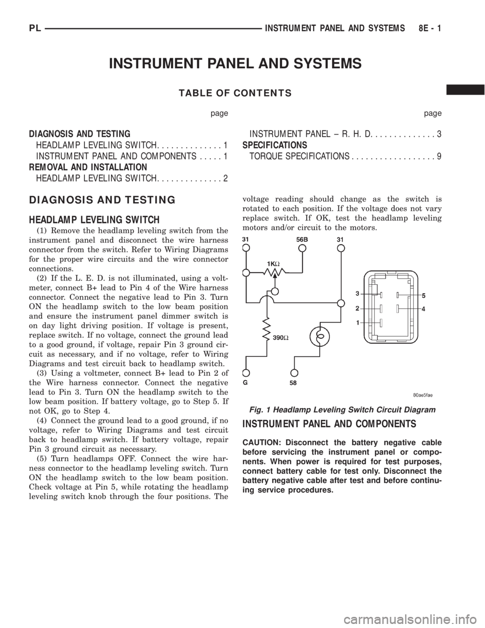
(1) Remove the headlamp leveling switch from the
instrument panel and disconnect the wire harness
connector from the switch. Refer to Wiring Diagrams
for the proper wire circuits and the wire connector
connections.
(2) If the L. E. D. is not illuminated, using a volt-
meter, connect B+ lead to Pin 4 of the Wire harness
connector. Connect the negative lead to Pin 3. Turn
ON the headlamp switch to the low beam position
and ensure the instrument panel dimmer switch is
on day light driving position. If voltage is present,
replace switch. If no voltage, connect the ground lead
to a good ground, if voltage, repair Pin 3 ground cir-
cuit as necessary, and if no voltage, refer to Wiring
Diagrams and test circuit back to headlamp switch.
(3) Using a voltmeter, connect B+ lead to Pin 2 of
the Wire harness connector. Connect the negative
lead to Pin 3. Turn ON the headlamp switch to the
low beam position. If battery voltage, go to Step 5. If
not OK, go to Step 4.
(4) Connect the ground lead to a good ground, if no
voltage, refer to Wiring Diagrams and test circuit
back to headlamp switch. If battery voltage, repair
Pin 3 ground circuit as necessary.
(5) Turn headlamps OFF. Connect the wire har-
ness connector to the headlamp leveling switch. Turn
ON the headlamp switch to the low beam position.
Check voltage at Pin 5, while rotating the headlamp
leveling switch knob through the four positions. Thevoltage reading should change as the switch is
rotated to each position. If the voltage does not vary
replace switch. If OK, test the headlamp leveling
motors and/or circuit to the motors.
INSTRUMENT PANEL AND COMPONENTS
CAUTION: Disconnect the battery negative cable
before servicing the instrument panel or compo-
nents. When power is required for test purposes,
connect battery cable for test only. Disconnect the
battery negative cable after test and before continu-
ing service procedures.
Fig. 1 Headlamp Leveling Switch Circuit Diagram
PLINSTRUMENT PANEL AND SYSTEMS 8E - 1
Page 295 of 1285
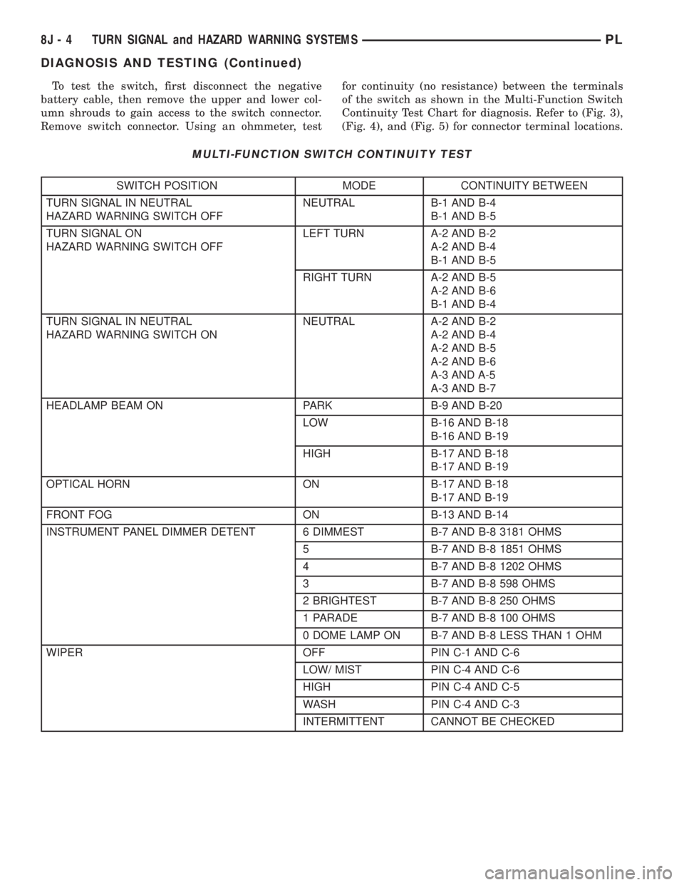
To test the switch, first disconnect the negative
battery cable, then remove the upper and lower col-
umn shrouds to gain access to the switch connector.
Remove switch connector. Using an ohmmeter, testfor continuity (no resistance) between the terminals
of the switch as shown in the Multi-Function Switch
Continuity Test Chart for diagnosis. Refer to (Fig. 3),
(Fig. 4), and (Fig. 5) for connector terminal locations.
MULTI-FUNCTION SWITCH CONTINUITY TEST
SWITCH POSITION MODE CONTINUITY BETWEEN
TURN SIGNAL IN NEUTRAL
HAZARD WARNING SWITCH OFFNEUTRAL B-1 AND B-4
B-1 AND B-5
TURN SIGNAL ON
HAZARD WARNING SWITCH OFFLEFT TURN A-2 AND B-2
A-2 AND B-4
B-1 AND B-5
RIGHT TURN A-2 AND B-5
A-2 AND B-6
B-1 AND B-4
TURN SIGNAL IN NEUTRAL
HAZARD WARNING SWITCH ONNEUTRAL A-2 AND B-2
A-2 AND B-4
A-2 AND B-5
A-2 AND B-6
A-3 AND A-5
A-3 AND B-7
HEADLAMP BEAM ON PARK B-9 AND B-20
LOW B-16 AND B-18
B-16 AND B-19
HIGH B-17 AND B-18
B-17 AND B-19
OPTICAL HORN ON B-17 AND B-18
B-17 AND B-19
FRONT FOG ON B-13 AND B-14
INSTRUMENT PANEL DIMMER DETENT 6 DIMMEST B-7 AND B-8 3181 OHMS
5 B-7 AND B-8 1851 OHMS
4 B-7 AND B-8 1202 OHMS
3 B-7 AND B-8 598 OHMS
2 BRIGHTEST B-7 AND B-8 250 OHMS
1 PARADE B-7 AND B-8 100 OHMS
0 DOME LAMP ON B-7 AND B-8 LESS THAN 1 OHM
WIPER OFF PIN C-1 AND C-6
LOW/ MIST PIN C-4 AND C-6
HIGH PIN C-4 AND C-5
WASH PIN C-4 AND C-3
INTERMITTENT CANNOT BE CHECKED
8J - 4 TURN SIGNAL and HAZARD WARNING SYSTEMSPL
DIAGNOSIS AND TESTING (Continued)