2000 DODGE NEON low beam
[x] Cancel search: low beamPage 311 of 1285
HEADLAMP ALIGNMENT
TABLE OF CONTENTS
page page
DESCRIPTION AND OPERATION
HEADLAMP ALIGNMENT....................4
SERVICE PROCEDURES
HEADLAMP ALIGNMENT PREPARATION........4ADJUSTMENTS
HEADLAMP ADJUSTMENT USING
ALIGNMENT SCREEN....................4
FOG LAMP ALIGNMENT....................6
DESCRIPTION AND OPERATION
HEADLAMP ALIGNMENT
Headlamps and Fog Lamps should be aligned
using the screen method which is provided in this
section.The preferred headlamp alignment set-
ting is 0 for the left/right adjustment and 0 for
the up/down adjustment.
SERVICE PROCEDURES
HEADLAMP ALIGNMENT PREPARATION
(1) Verify headlamp dimmer switch and high beam
indicator operation.
(2) Inspect and correct damaged or defective com-
ponents that could interfere with proper headlamp
alignment.
(3) Verify proper tire inflation.
(4) Clean headlamp lenses.
(5) Verify that luggage area is not heavily loaded.
(6) Fuel tank should be FULL. Add 2.94 kg (6.5
lbs.) of weight over the fuel tank for each estimated
gallon of missing fuel.
ADJUSTMENTS
HEADLAMP ADJUSTMENT USING ALIGNMENT
SCREEN
ALIGNMENT SCREEN PREPARATION
(1) Position vehicle on a level surface perpendicu-
lar to a flat wall 7.62 meters (25 ft.) away from front
of headlamp lens.
(2) If necessary, tape a line on the floor 7.62
meters (25 ft.) away from and parallel to the wall
(Fig. 1).(3) From the floor up 1.27 meters (5 ft.), tape a
line on the wall at the center line of the vehicle.
Sight along the center line of the vehicle (from rear
of vehicle forward) to verify accuracy of the line
placement.
(4) Rock vehicle side-to-side three times to allow
suspension to stabilize.
(5) Jounce front suspension three times by pushing
downward on front bumper and releasing.
(6) A small dot is molded into each headlamp lens
signifying the center of the headlamp. Measure the
distance from the center of the headlamp to the floor.
Transfer measurement to the alignment screen (with
tape). Use this line for up/down adjustment refer-
ence.
(7) Measure distance from the center line of the
vehicle to the center of each headlamp being aligned.
Transfer measurements to screen (with tape) to each
side of vehicle center line. Use these lines for left/
right adjustment reference.
HEADLAMP ADJUSTMENT
The PL headlamp low beam pattern has a distinct
horizontal cutoff line which is used to visually align
the headlamps. A properly aimed headlamp will have
the horizontal cutoff line of the low beam pattern
centered on the low beam pattern centered on the
horizontal center of headlamp line. The side to side
left edge of the low beam hot spot should be located
75 mm (3 inches) to the left of the headlamp center
line (Fig. 1). The high beams on a vehicle with aero
headlamps cannot be aligned. The high beam pattern
should be correct when the low beams are aligned
properly.
To adjust headlamp alignment, rotate alignment
screws to achieve the specified low beam hot spot
pattern.
8L - 4 LAMPSPL
Page 312 of 1285
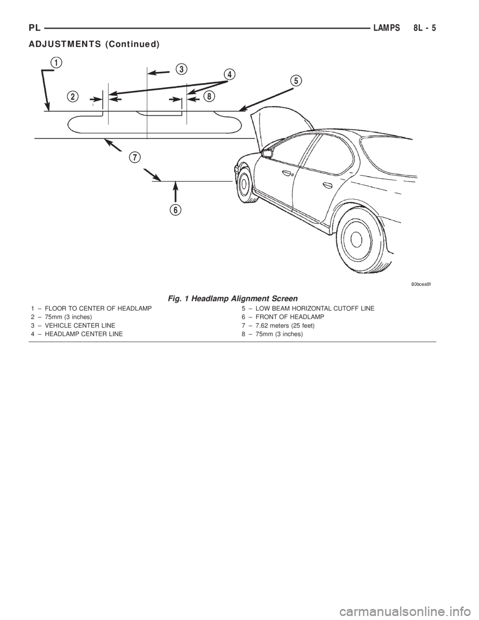
Fig. 1 Headlamp Alignment Screen
1 ± FLOOR TO CENTER OF HEADLAMP
2 ± 75mm (3 inches)
3 ± VEHICLE CENTER LINE
4 ± HEADLAMP CENTER LINE5 ± LOW BEAM HORIZONTAL CUTOFF LINE
6 ± FRONT OF HEADLAMP
7 ± 7.62 meters (25 feet)
8 ± 75mm (3 inches)
PLLAMPS 8L - 5
ADJUSTMENTS (Continued)
Page 324 of 1285
BULB APPLICATION
TABLE OF CONTENTS
page page
SPECIFICATIONS
EXTERIOR LAMPS........................17INTERIOR LAMPS........................17
SPECIFICATIONS
EXTERIOR LAMPS
CAUTION: Do not use bulbs that have a higher can-
dle power than the bulb listed in the chart below.
Damage to lamp can result. Do not touch halogen
bulbs with fingers or other oily surfaces. Bulb life
will be reduced.
LAMP BULB
Back Up Lamp................3157 ± P27/7W
Center High Mounted Stop Lamp
(CHMSL).........................W16W
Front Fog Lamp..................... GE881
Front Park/Turn Signal Lamp..........3157NA
Front Side Marker Lamp................. 168
Headlamp............................9007
License Plate Lamp..................... 168
Rear Tail/Stop/
Turn Signal Lamp............3157 ± P27/7W
INTERIOR LAMPS
Service procedures for most of the lamps in the
instrument panel, Instrument cluster and switches
are located in Group 8E, Instrument Panel and
Gauges.
CAUTION: Do not use bulbs that have a higher can-
dle power than the bulb listed in the chart below.
Damage to lamp can result.LAMP BULB
ABS Indicator......................... LED
Airbag Indicator....................... LED
Brake System Warning Indicator.......... LED
Climate Controls....................... LED
Console Gear Selector W/Auto...........PC194
Dome Lamp..........................T579
Floor Console Lamp..................... T37
Front Fog Lamp Indicator................ LED
Glove Compartment....................T194
High Beam Lamp Indicator.............PC194
Ignition Lock........................... 161
Instrument Cluster Illumination.........PC194
Low Fuel Indicator..................... LED
Low Oil Pressure Indicator............... LED
Rear Cargo...........................T906
Seat Belt Indicator..................... LED
Security Alarm Indicator................. LED
Malfunction Indicator Light.............. LED
TRAC OFF Indicator.................... LED
Turn Signal Indicator..................PC194
Underhood............................ 105
Visor Vanity........................6501966
Voltage Indicator....................... LED
All the inside bulbs brass or glass wedge base. Alu-
minum base bulbs are not approved and should not
be used for replacement.
PLLAMPS 8L - 17
Page 327 of 1285
HEADLAMP ALIGNMENT
TABLE OF CONTENTS
page page
DESCRIPTION AND OPERATION
HEADLAMP ALIGNMENT....................2
SERVICE PROCEDURES
HEADLAMP ALIGNMENT PREPARATION........2ADJUSTMENTS
HEADLAMP ADJUSTMENT USING
ALIGNMENT SCREEN....................2
DESCRIPTION AND OPERATION
HEADLAMP ALIGNMENT
Headlamps can be aligned using the screen method
provided in this section. This method will require the
vehicle to be parked on a flat, level surface with a
minimum of 15 meters of working room in front of a
flat, level perpendicular wall or aiming.
Each headlamp has a focal point circle molded on
the lens directly in front of each headlamp bulb.
These focal point circles are used to set up lines on a
wall, or aiming board for visually aiming the head-
lamps.
The driving (high) beam location does not require
adjustment. It will be correct when the passing (low)
beam headlamps are aimed correctly.
SERVICE PROCEDURES
HEADLAMP ALIGNMENT PREPARATION
(1) Verify headlamp dimmer switch and high beam
indicator operation.
(2) Inspect and correct damaged or defective com-
ponents that could interfere with proper headlamp
alignment.
(3) Verify that the headlamp leveling switch is in
the ª0º position.
(4) Verify proper tire inflation.
(5) Clean the headlamp lenses.
(6) Verify that the luggage area is not heavily
loaded.
(7) Fuel tank should be FULL. Add 2.94 kg (6.5
lbs.) of weight over the fuel tank for each estimated
gallon of missing fuel.
ADJUSTMENTS
HEADLAMP ADJUSTMENT USING ALIGNMENT
SCREEN
ALIGNMENT SCREEN PREPARATION
(1) Position the vehicle on a level surface 10
meters in front of a level, flat wall or aiming board.
(2) Tape a vertical line on the wall extending 1
meter up from the floor, making sure this line is even
with the centerline of the vehicle (Fig. 1).
(3) Measure the cross-car distance between the
two headlamp focal point circles (1174mm). Transfer
half of this distance (587mm) to the left of the vehicle
centerline and tape another vertical line up from the
floor 1 meter (Fig. 1). Repeat for the right side of the
centerline.
(4) Measure the distance from the floor to the focal
point circle on the headlamp lens (635mm, but may
vary due to variations in tire size and vehicle suspen-
sion height). Transfer this measurement to the wall
and tape a horizontal line extending approximately 1
meter beyond each vertical focal point line (Fig. 1).
(5) Use these lines for left and right adjustment
reference.
HEADLAMP ADJUSTMENT
Horizontal Adjustment
The horizontal position of the passing (low) beam
pattern is adjusted by turning the T-15 Torx screw.
Located through the slot in the upper-crossmember
between the two attaching straps of the headlamp.
Vertical Adjustment
The vertical position of the passing (low) beam pat-
tern is adjusted by turning the Phillips screw on top
of the headlamp leveling motor. Located between the
headlamp housing and the upper-crossmember, just
inboard of the fender.
Adjust the passing (low) beam headlamp pat-
terns to the locations shown in the chart pro-
vided (Fig. 1).
8L - 2 LAMPSPL
Page 344 of 1285
BULB APPLICATION
TABLE OF CONTENTS
page page
GENERAL INFORMATION
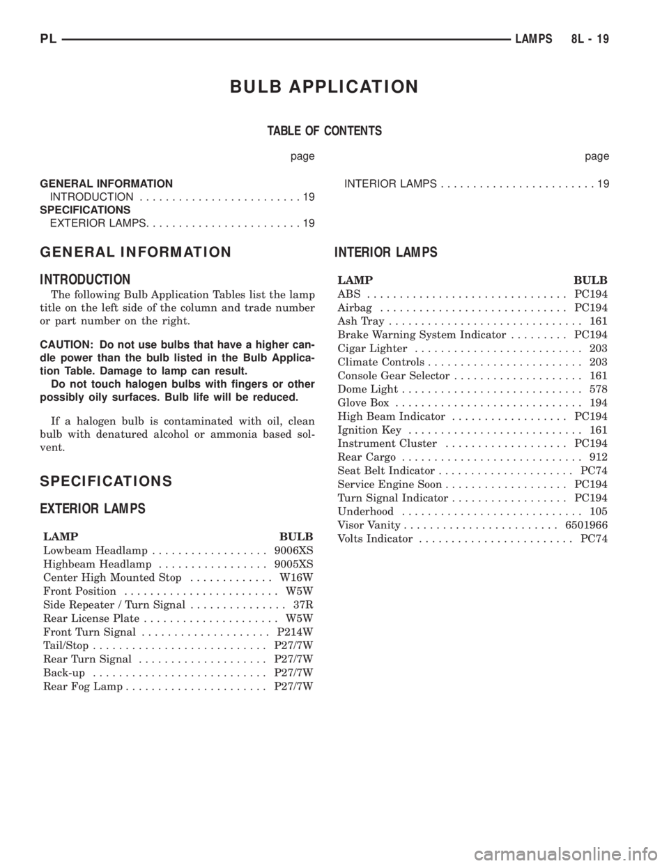
INTRODUCTION.........................19
SPECIFICATIONS
EXTERIOR LAMPS........................19INTERIOR LAMPS........................19
GENERAL INFORMATION
INTRODUCTION
The following Bulb Application Tables list the lamp
title on the left side of the column and trade number
or part number on the right.
CAUTION: Do not use bulbs that have a higher can-
dle power than the bulb listed in the Bulb Applica-
tion Table. Damage to lamp can result.
Do not touch halogen bulbs with fingers or other
possibly oily surfaces. Bulb life will be reduced.
If a halogen bulb is contaminated with oil, clean
bulb with denatured alcohol or ammonia based sol-
vent.
SPECIFICATIONS
EXTERIOR LAMPS
LAMP BULB
Lowbeam Headlamp..................9006XS
Highbeam Headlamp.................9005XS
Center High Mounted Stop.............W16W
Front Position........................ W5W
Side Repeater / Turn Signal............... 37R
Rear License Plate..................... W5W
Front Turn Signal....................P214W
Tail/Stop...........................P27/7W
Rear Turn Signal....................P27/7W
Back-up...........................P27/7W
Rear Fog Lamp......................P27/7W
INTERIOR LAMPS
LAMP BULB
ABS ...............................PC194
Airbag.............................PC194
AshTray .............................. 161
Brake Warning System Indicator.........PC194
Cigar Lighter.......................... 203
Climate Controls........................ 203
Console Gear Selector.................... 161
Dome Light............................ 578
Glove Box............................. 194
High Beam Indicator..................PC194
Ignition Key........................... 161
Instrument Cluster...................PC194
Rear Cargo............................ 912
Seat Belt Indicator.....................PC74
Service Engine Soon...................PC194
Turn Signal Indicator..................PC194
Underhood............................ 105
Visor Vanity........................6501966
Volts Indicator........................PC74
PLLAMPS 8L - 19
Page 410 of 1285
8W-02 COMPONENT INDEX
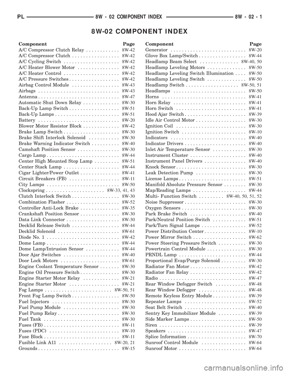
Component Page
A/C Compressor Clutch Relay............8W-42
A/C Compressor Clutch.................8W-42
A/C Cycling Switch....................8W-42
A/C Heater Blower Motor...............8W-42
A/C Heater Control....................8W-42
A/C Pressure Switches..................8W-42
Airbag Control Module.................8W-43
Airbags.............................8W-43
Antenna.............................8W-47
Automatic Shut Down Relay.............8W-30
Back-Up Lamp Switch..................8W-51
Back-Up Lamps.......................8W-51
Battery.............................8W-20
Blower Motor Resistor Block.............8W-42
Brake Lamp Switch....................8W-30
Brake Shift Interlock Solenoid...........8W-30
Brake Warning Indicator Switch..........8W-40
Camshaft Position Sensor...............8W-30
Cargo Lamp..........................8W-44
Center High Mounted Stop Lamp.........8W-51
Center Stack Lamp....................8W-44
Cigar Lighter/Power Outlet..............8W-41
Circuit Breakers (FB)..................8W-11
City Lamps..........................8W-50
Clockspring.....................8W-33, 41, 43
Clutch Interlock Switch.................8W-30
Combination Flasher...................8W-52
Controller Anti-Lock Brake..............8W-35
Crankshaft Position Sensor..............8W-30
Data Link Connector...................8W-30
Decklid Release Switch.................8W-44
Decklid Solenoid......................8W-61
Diode No. 1..........................8W-42
Dome Lamp..........................8W-44
Dome Lamp/Intrusion Sensor............8W-44
Door Ajar Switches....................8W-40
Door Lock Motors.....................8W-61
Engine Coolant Temperature Sensor.......8W-30
Engine Oil Pressure Switch..............8W-30
Engine Starter Motor Relay.............8W-21
Engine Starter Motor..................8W-21
Fog Lamps........................8W-50, 51
Front Fog Lamp Switch.................8W-50
Fuel Injectors........................8W-30
Fuel Pump Module....................8W-30
Fuel Pump Relay......................8W-30
Fuel Tank...........................8W-30
Fuses (FB)...........................8W-11
Fuses (PDC).........................8W-10
Fuse Block...........................8W-11
Fusible Link A11...................8W-20, 21
Grounds.............................8W-15Component Page
Generator...........................8W-20
Glove Box Lamp/Switch.................8W-44
Headlamp Beam Select..............8W-40, 50
Headlamp Leveling Motors..............8W-50
Headlamp Leveling Switch Illumination....8W-50
Headlamp Leveling Switch..............8W-50
Headlamp Switch...................8W-50, 51
Headlamps..........................8W-50
Horns..............................8W-41
Horn Relay..........................8W-41
Horn Switch.........................8W-41
Hood Ajar Switch......................8W-39
Idle Air Control Motor..................8W-30
Ignition Coil.........................8W-30
Ignition Switch.......................8W-10
Indicators...........................8W-40
Indicator Drivers......................8W-40
Inlet Air Temperature Sensor............8W-30
Instrument Cluster....................8W-40
Instrument Panel Drivers...............8W-40
Knock Sensor.........................8W-30
Leak Detection Pump..................8W-30
License Lamps........................8W-51
Manifold Absolute Pressure Sensor........8W-30
Map/Reading Lamps...................8W-44
Multi- Function Switch.........8W-40, 50, 51, 52
Noise Suppressor......................8W-30
Oxygen Sensors.......................8W-30
Park Brake Switch....................8W-40
Park/Neutral Position Switch............8W-51
Park/Turn Signal Lamps................8W-52
Power Distribution Center...............8W-10
Power Mirror Switch...................8W-62
Power Steering Pressure Switch..........8W-30
Powertrain Control Module..............8W-30
PRNDL Lamp........................8W-44
Proportional Evap/Purge Solenoid.........8W-30
Radiator Fan Motor....................8W-42
Radiator Fan Relay....................8W-42
Radio...............................8W-47
Rear Window Defogger Switch...........8W-48
Rear Window Defogger.................8W-48
Remote Keyless Entry Module............8W-39
Repeater Lamps......................8W-52
Seat Belt Switch......................8W-40
Sentry Key Immobilizer Module..........8W-39
Side Marker Lamps....................8W-50
Siren...............................8W-39
Speakers............................8W-47
Splice Information.....................8W-70
Sunroof Control Module................8W-64
Sunroof Motor........................8W-64
PL8W - 02 COMPONENT INDEX 8W - 02 - 1
Page 449 of 1285

25A NO. 2
BREAKER
CIRCUIT4443
BLOCK FUSE
17
MULTI-
0
123 LOW 2 HEAD
1 PARK
0 OFF
SWITCH
FUNCTION
1819
16 HEADLAMP
SWITCH5 FLASH 4 HIGH
S209
F3
12
LB/ORF3
12
LB/OR
F3
12
LB/OR
L3
14
RD/OR
H
(8W-11-21)TO
S215
L4
14
VT/WT
G
(8W-11-20)F
(8W-11-19)
MULTI-
FUNCTION
SWITCH
TO
FUSE
BLOCK
TO201
MODULE ENTRY
KEYLESS
REMOTE
L4
14
VT/WTL4
14
VT/WTL4
16
VT/WTL4
16
VT/WT
S212 BATT A3
HEADLAMP
BEAM
SELECT
5 4 3
EXPORT) BUILT-UP-
LHD
(EXCEPT
CLUSTER
INSTRUMENT
EXPORT BUILT-UP-EXCEPTBUILT-UP-
EXPORT EXPORT BUILT-UP- BUILT-UP-
EXPORTEXCEPT
(8W-11-2)
(8W-11-3)
(8W-50-2)
(8W-50-4)
(8W-39-12)
(8W-39-13) (8W-10-9)
(8W-40-12) (8W-11-19)
8W - 11 - 18 8W-11 FUSE BLOCKPL
008W-10PLI01118
Page 505 of 1285

1
MODULE ENTRY
KEYLESS
REMOTE
20
CLUSTER
INSTRUMENT17
37
10A
FUSE
17 18FUSE
10A
38 18
BLOCK FUSE
1 1
21C10325 B25B21
L44
14
VT/RD
L44
16
VT/RD
L44
14
VT/RDL43
12
VT
L43
16
VT
L43
14
VT
L4
14
VT/WT
L4
16
VT/WT
L4
16
VT/WT
S212
HEADLAMP LEFT
HEADLAMP RIGHT S102 S101
DIMMER
SWITCH
LOW
BEAM
OUTPUT
DIMMER
SWITCH
LOW
BEAM
OUTPUT
FUSED
LEFT
LOW
BEAM
OUTPUT OUTPUTBEAMLOW RIGHT FUSED(8W-40-12)
(8W-11-19) (8W-11-19)(8W-11-2)(8W-11-20)
(8W-50-3) (8W-50-3)(8W-11-19) (8W-11-19)
8W - 39 - 12 8W-39 VEHICLE THEFT SECURITY SYSTEM
EXCEPT BUILT-UP-EXPORTPL
008W-10PLI03912