2000 DODGE NEON steering wheel adjustment
[x] Cancel search: steering wheel adjustmentPage 12 of 1285
SUSPENSION
TABLE OF CONTENTS
page page
WHEEL ALIGNMENT........................ 1
FRONT SUSPENSION....................... 9REAR SUSPENSION....................... 35
WHEEL ALIGNMENT
TABLE OF CONTENTS
page page
DESCRIPTION AND OPERATION
WHEEL ALIGNMENT.......................1
DIAGNOSIS AND TESTING
SUSPENSION AND STEERING DIAGNOSIS.....3
SERVICE PROCEDURES
CURB HEIGHT MEASUREMENT..............5WHEEL ALIGNMENT.......................5
SPECIFICATIONS
WHEEL ALIGNMENT SPECIFICATIONS.........8
DESCRIPTION AND OPERATION
WHEEL ALIGNMENT
Proper vehicle wheel alignment is the proper
adjustment of all interrelated front and rear suspen-
sion angles. These angles are what affects the han-
dling and steering of the vehicle when it is in motion.
The method of checking a vehicle's front and rear
wheel alignment will vary depending on the type and
manufacturer of the equipment being used. Instruc-
tions furnished by the manufacturer of the equip-
ment being used should always be followed to ensure
accuracy of the alignment, except when alignment
specifications recommended by this corporation differ.
Typical wheel alignment angles and measurements
are camber, caster, toe, and thrust angle.
²Camber is the number of degrees the top of the
tire and wheel are tilted either inward or outward
(Fig. 1). Camber is a tire wearing angle. Excessive
negative camber will cause tread wear at the inside
of the tire, while excessive positive camber will cause
outside tire wear.²Caster is the number of degrees of forward or
rearward tilt of the steering knuckle. Forward tilt
provides a negative caster angle, while rearward tilt
provides a positive caster angle. Caster is not adjust-
able on this vehicle.
²Cross Camber is the difference between left and
right camber. The right side camber is to be sub-
tracted from the left, resulting in the cross camber
reading. For example, if the left camber is +0.3É and
the right camber is 0.0É, the cross camber would be
+0.3É.
²Toe is measured in degrees or inches and is the
difference in width between the centered leading and
trailing edges of the tires on the same axle (Fig. 1).
Toe-in means that the front width is more narrow
than the rear. Toe-out means that the front width is
wider than the rear.
²Thrust Angle is defined as the average of the toe
settings on each rear wheel. If this measurement is
out of specification, readjust the rear wheel toe so
that each wheel has 1/2 of the total toe measure-
ment. When readjusting, do not exceed the total toe
specification.
PLSUSPENSION 2 - 1
Page 15 of 1285
CONDITION POSSIBLE CAUSES POTENTIAL CORRECTIONS
3. Loose Wheel Lug Nuts 3. Verify Wheel Lug Nut Torque
4. Worn Or Broken C/V Joint 4. Replace C/V Joint
5. Worn Or Loose Ball Joint 5. Tighten Or Replace Ball Joint
6. Worn Or Loose Control Arm Bushing 6. Tighten To Specified Torque Or Replace
Control Arm Bushing
7. Loose Crossmember Bolts 7. Tighten Crossmember Bolts To Specified
Torque
Road Wander 1. Incorrect Tire Pressure 1. Inflate Tires To Rcommended Pressure
2. Incorrect Front Or Rear Wheel Toe 2. Check And Reset Front Wheel Toe
3. Worn Wheel Bearings 3. Replace Wheel Bearing
4. Worn Control Arm Bushings 4. Replace Control Arm Bushing
5. Excessive Friction In Steering Gear 5. Replace Steering Gear
6. Excessive Friction In Steering Shaft
Coupling6. Replace Steering Coupler
7. Excessive Friction In Strut Upper
Bearing7. Replace Strut Bearing
Lateral Pull 1. Unequal Tire Pressure 1. Inflate All Tires To Recommended
Pressure
2. Radial Tire Lead 2. Perform Lead Correction Procedure
3. Incorrect Front Wheel Camber 3. Check And Reset Front Wheel Camber
4. Power Steering Gear Imbalance 4. Replace Power Steering Gear
5. Wheel Braking 5. Correct Braking Condition Causing
Lateral Pull
Excessive Steering
Free Play1. Incorrect Steering Gear Adjustment 1. Adjust Or Replace Steering Gear
2. Worn Or Loose Tie Rod Ends 2. Replace Or Tighten Tie Rod Ends
3. Loose Steering Gear Mounting Bolts 3. Tighten Steering Gear Bolts To The
Specified Torque
4. Loose Or Worn Steering Shaft Coupler 5. Replace Steering Shaft Coupler
Excessive Steering
Effort1. Low Tire Pressure 1. Inflate All Tires To Recommended
Pressure
2. Lack Of Lubricant In Steering Gear 2. Replace Steering Gear
3. Low Power Steering Fluid Level 3. Fill Power Steering Fluid Reservoir To
Correct Level
4. Loose Power Steering Pump Belt 4. Check and replace automatic belt
tensioner as necessary. If drive belt is worn
or glazed, replace belt.
5. Lack Of Lubricant In Steering Ball Joints 5. Lubricate Or Replace Steering Ball Joints
6. Steering Gear Malfunction 6. Replace Steering Gear
7. Lack Of Lubricant In Steering Coupler 7. Replace Steering Coupler
2 - 4 SUSPENSIONPL
DIAGNOSIS AND TESTING (Continued)
Page 16 of 1285
SERVICE PROCEDURES
CURB HEIGHT MEASUREMENT
The wheel alignment is to be checked and all align-
ment adjustments made with the vehicle at its
required curb height specification.
Vehicle height is to be checked with the vehicle on
a flat, level surface, preferably a vehicle alignment
rack. The tires are to be inflated to the recommended
pressure. All tires are to be the same size as stan-
dard equipment. Vehicle height is checked with the
fuel tank full of fuel, and no passenger or luggage
compartment load.
Vehicle height is not adjustable. If the measure-
ment is not within specifications, inspect the vehicle
for bent or weak suspension components. Compare
the parts tag on the suspect coil spring(s) to the
parts book and the vehicle sales code, checking for a
match. Once removed from the vehicle, compare thecoil spring height to a correct new or known good coil
spring. The heights should vary if the suspect spring
is weak.
NOTE: Prior to reading the curb height measure-
ment, the front an rear of the vehicle should be
jounced. Induce jounce by grasping the center of
the rear, then front bumper (or fascia) and jouncing
the vehicle an equal number of times. Release the
bumper at the bottom of the jounce cycle.
(1) Measure from the inboard edge of the wheel
opening fender lip directly above the wheel center
(spindle), to the floor or alignment rack surface.
(2) When measuring, maximum left-to-right differ-
ential is not to exceed 10 mm (0.39 in.).
(3) Compare the measurements to specifications
listed in the following CURB HEIGHT SPECIFICA-
TIONS chart.
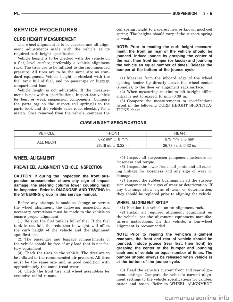
CURB HEIGHT SPECIFICATIONS
VEHICLE FRONT REAR
ALL NEON672 mm68 mm 679 mm68mm
26.46 in.60.32 in. 26.73 in.60.32 in.
WHEEL ALIGNMENT
PRE-WHEEL ALIGNMENT VEHICLE INSPECTION
CAUTION: If during the inspection the front sus-
pension crossmember shows any sign of impact
damage, the steering column lower coupling must
be inspected. Refer to DIAGNOSIS AND TESTING in
the STEERING group in this service manual.
Before any attempt is made to change or correct
the wheel alignment, the following inspection and
necessary corrections must be made to the vehicle to
ensure proper alignment.
(1) Be sure the fuel tank is full of fuel. If the fuel
tank is not full, the reduction in weight will affect
the curb height of the vehicle and the alignment
specifications.
(2) The passenger and luggage compartments of
the vehicle should be free of any load that is not fac-
tory equipment.
(3) Check the tires on the vehicle. The tires are to
be inflated to the recommended air pressure. All tires
must be the same size and in good condition with
approximately the same tread wear.
(4) Check the front tire and wheel assemblies for
excessive radial runout.(5) Inspect all suspension component fasteners for
looseness and torque.
(6) Inspect the lower front ball joints and all steer-
ing linkage for looseness and any sign of wear or
damage.
(7) Inspect the rubber bushings on all the suspen-
sion components for signs of wear or deterioration. If
any bushings show signs of wear or deterioration,
they should be replaced prior to aligning the vehicle.
WHEEL ALIGNMENT SETUP
(1) Position the vehicle on an alignment rack.
(2) Install all required alignment equipment on
the vehicle, per the alignment equipment manufac-
turer's instructions. On this vehicle, a four-wheel
alignment is recommended.
NOTE: Prior to reading the vehicle's alignment
readouts, the front and rear of vehicle should be
jounced. Induce jounce (rear first, then front) by
grasping the center of the bumper and jouncing
each end of vehicle an equal number of times. The
bumper should always be released when vehicle is
at the bottom of the jounce cycle.
(3) Read the vehicle's current front and rear align-
ment settings. Compare the vehicle's current align-
ment settings to the vehicle specifications for camber,
caster and toe-in. Refer to WHEEL ALIGNMENT
PLSUSPENSION 2 - 5
Page 17 of 1285
SPECIFICATIONS in this section of this service
manual group.
(4) If the rear alignment is out of specification,
adjust it first before proceeding to the front.
CAMBER AND CASTER
Front and rear camber and caster settings on this
vehicle are determined at the time the vehicle is
designed, by the location of the vehicle's suspension
components. This is referred to as Net Build. The
result is no required adjustment of camber and
caster after the vehicle is built or when servicing the
suspension components. Thus, when performing a
wheel alignment, caster and camber are not normally
considered adjustable angles. Camber and caster
should be checked to ensure they meet vehicle speci-
fications.
If either front or rear camber is found not to meet
alignment specifications, it can be adjusted using an
available camber adjustment bolt package. Before
installing a camber adjustment bolt package on a
vehicle found to be outside the specifications, inspect
the suspension components for any signs of damage
or bending.
No adjustment can be made to the caster setting
on this vehicle. If the vehicle's caster is not within
alignment specifications, check for damaged suspen-
sion components or body parts.
CAUTION: Do not attempt to adjust the vehicles
wheel alignment by heating or bending any of the
suspension components.
CAMBER ADJUSTMENT BOLT PACKAGE INSTALLATION
NOTE: The following procedure should only be
used on vehicles without the ACR competition
package.
The camber adjustment bolt package contains new
bolts and nuts for attaching the strut clevis bracket
to the steering knuckle. The bolts contained in the
package are slightly undersize allowing for move-
ment between the strut clevis bracket and the steer-
ing knuckle. The movement allowed by the undersize
bolts provide approximately two degrees of camber
adjustment per side of the vehicle. To install and
adjust the camber adjustment bolt package, follow
the procedure below.
CAUTION: There are separate camber adjustment
bolt packages for the front and rear of the vehicle.
Be sure to use the correct package.
(1) Raise the vehicle until its tires are not support-
ing the weight of the vehicle.CAUTION: The knuckle to strut assembly attaching
bolt shanks are serrated and must not be turned
during removal. Remove the nuts while holding the
bolts stationary.
(2) Remove the original upper bolt attaching the
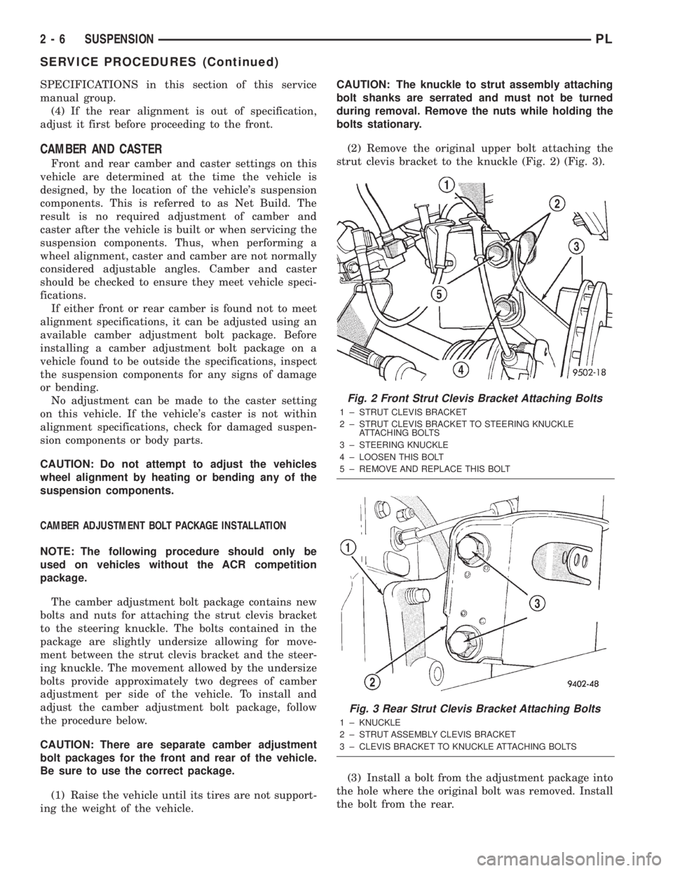
strut clevis bracket to the knuckle (Fig. 2) (Fig. 3).
(3) Install a bolt from the adjustment package into
the hole where the original bolt was removed. Install
the bolt from the rear.
Fig. 2 Front Strut Clevis Bracket Attaching Bolts
1 ± STRUT CLEVIS BRACKET
2 ± STRUT CLEVIS BRACKET TO STEERING KNUCKLE
ATTACHING BOLTS
3 ± STEERING KNUCKLE
4 ± LOOSEN THIS BOLT
5 ± REMOVE AND REPLACE THIS BOLT
Fig. 3 Rear Strut Clevis Bracket Attaching Bolts
1 ± KNUCKLE
2 ± STRUT ASSEMBLY CLEVIS BRACKET
3 ± CLEVIS BRACKET TO KNUCKLE ATTACHING BOLTS
2 - 6 SUSPENSIONPL
SERVICE PROCEDURES (Continued)
Page 18 of 1285
(4) Install a nut provided in adjustment package
on the replacement bolt. Tighten the nut until it's
snug, but still allowing the knuckle to slide in the
clevis bracket.
(5) Remove the original lower bolt.
(6) Install a bolt from the adjustment package into
the bottom hole of the strut clevis bracket. Install the
bolt from the rear.
(7) Install a nut provided in adjustment package
on the replacement bolt. Tighten the nut until it's
snug.
(8) Reinstall the tire and wheel assembly.
(9) Perform the above procedure to any of the
remaining struts as required.
(10) Lower the vehicle and jounce the front and
rear of the vehicle.
(11) Adjust the front or rear camber to the pre-
ferred setting by pushing or pulling on the top of the
tire. When camber is set to specifications, tighten the
upper and lower strut clevis bracket bolts. Again
jounce the front and rear of the vehicle, then verify
the camber settings.
(12) Torque front strut clevis bracket-to-steering
knuckle attaching bolts to 53 N´m (40 ft. lbs.), plus
an additional 1/4 turn after the torque is met. Torque
the rear strut clevis bracket-to-rear knuckle attach-
ing bolts to 95 N´m (70 ft. lbs.).
(13) Once camber is within specifications, adjust
toe to meet the preferred specification setting. Refer
to TOE within this wheel alignment service proce-
dure.
TOE
(1) Center the steering wheel and lock it in place
using a steering wheel clamp.
NOTE: When performing the toe setting procedure,
make sure the rear toe is set to the preferred spec-
ification before setting the front toe to the preferred
specification.
REAR TOE
(1) Loosen the nuts on the left and right rear lat-
eral link attaching bolts at the rear crossmember as
necessary to allow rotation of the rear toe adjustment
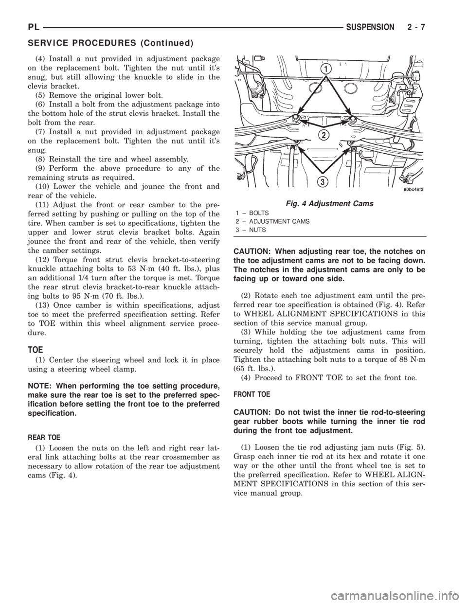
cams (Fig. 4).CAUTION: When adjusting rear toe, the notches on
the toe adjustment cams are not to be facing down.
The notches in the adjustment cams are only to be
facing up or toward one side.
(2) Rotate each toe adjustment cam until the pre-
ferred rear toe specification is obtained (Fig. 4). Refer
to WHEEL ALIGNMENT SPECIFICATIONS in this
section of this service manual group.
(3) While holding the toe adjustment cams from
turning, tighten the attaching bolt nuts. This will
securely hold the adjustment cams in position.
Tighten the attaching bolt nuts to a torque of 88 N´m
(65 ft. lbs.).
(4) Proceed to FRONT TOE to set the front toe.
FRONT TOE
CAUTION: Do not twist the inner tie rod-to-steering
gear rubber boots while turning the inner tie rod
during the front toe adjustment.
(1) Loosen the tie rod adjusting jam nuts (Fig. 5).
Grasp each inner tie rod at its hex and rotate it one
way or the other until the front wheel toe is set to
the preferred specification. Refer to WHEEL ALIGN-
MENT SPECIFICATIONS in this section of this ser-
vice manual group.
Fig. 4 Adjustment Cams
1 ± BOLTS
2 ± ADJUSTMENT CAMS
3 ± NUTS
PLSUSPENSION 2 - 7
SERVICE PROCEDURES (Continued)
Page 125 of 1285
(4) Remove the brake drum (Fig. 87).
NOTE: If the drum does not come off, further brake
clearance can be obtained by backing off the brake
automatic adjuster screw. Remove the rubber plug
from the top of brake support plate. Rotate the
automatic adjuster screw in an upward motion,
using a screwdriver.
INSTALLATION
NOTE: Before installing the drum, inspect the brake
shoe linings for wear, shoe alignment, and contam-
ination.
(1) Install the rear brake drum on rear hub and
bearing (Fig. 87).
(2) Install the tire and wheel assembly. Tighten
the wheel mounting nuts to a torque of 135 N´m (100
ft. lbs.).
(3) Adjust the rear brake shoes as necessary. Refer
to ADJUSTMENTS in this section of this service
manual group.
(4) Lower the vehicle.
DRUM BRAKE SHOE SUPPORT PLATE (REAR)
NOTE: Before proceeding with this procedure,
review SERVICE WARNINGS AND CAUTIONS at the
beginning of REMOVAL AND INSTALLATION in this
section.
REMOVAL
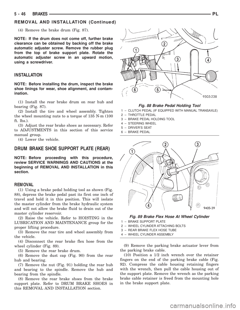
(1) Using a brake pedal holding tool as shown (Fig.
88), depress the brake pedal past its first one inch of
travel and hold it in this position. This will isolate
the master cylinder from the brake hydraulic system
and will not allow the brake fluid to drain out of the
master cylinder reservoir.
(2) Raise the vehicle. Refer to HOISTING in the
LUBRICATION AND MAINTENANCE group for the
proper lifting procedure.
(3) Remove the rear tire and wheel assembly from
the vehicle.
(4) Disconnect the rear brake flex hose from the
wheel cylinder (Fig. 89).
(5) Remove the rear brake drum.
(6) Remove the dust cap (Fig. 90) from the rear
hub and bearing.
(7) Remove the nut (Fig. 91) holding the rear hub
and bearing to the spindle. Remove the hub and
bearing from the spindle.
(8) Remove the rear brake shoes from the brake
support plate. Refer to DRUM BRAKE SHOES in
this REMOVAL AND INSTALLATION section.(9) Remove the parking brake actuator lever from
the parking brake cable.
(10) Position a 1/2 inch wrench over the retainer
fingers on the end of the parking brake cable (Fig.
92). Compress the cable housing retaining fingers
with the wrench, then pull the cable housing out of
the support plate. Remove the wrench as the parking
brake cable retainer is freed from the mounting hole
in the brake support plate.
Fig. 88 Brake Pedal Holding Tool
1 ± CLUTCH PEDAL (IF EQUIPPED WITH MANUAL TRANSAXLE)
2 ± THROTTLE PEDAL
3 ± BRAKE PEDAL HOLDING TOOL
4 ± STEERING WHEEL
5 ± DRIVER'S SEAT
6 ± BRAKE PEDAL
Fig. 89 Brake Flex Hose At Wheel Cylinder
1 ± BRAKE SUPPORT PLATE
2 ± WHEEL CYLINDER ATTACHING BOLTS
3 ± REAR BRAKE FLEX HOSE TUBE
4 ± WHEEL CYLINDER ASSEMBLY
5 - 46 BRAKESPL
REMOVAL AND INSTALLATION (Continued)
Page 298 of 1285
WINDSHIELD WIPER and WASHER SYSTEMS
TABLE OF CONTENTS
page page
WINDSHIELD WIPER SYSTEM................ 1WINDSHIELD WASHER SYSTEM.............. 8
WINDSHIELD WIPER SYSTEM
TABLE OF CONTENTS
page page
GENERAL INFORMATION
INTRODUCTION..........................1
DESCRIPTION AND OPERATION
WIPER BLADES...........................1
DIAGNOSIS AND TESTING
WINDSHIELD WIPER CONDITIONS............2
WINDSHIELD WIPER MOTOR................3
WINDSHIELD WIPER/WASHER SWITCH........5
REMOVAL AND INSTALLATION
WINDSHIELD WIPER ARM(S)................5WINDSHIELD WIPER BLADE(S)..............5
WINDSHIELD WIPER BLADE ELEMENT........5
WINDSHIELD WIPER LINKAGE...............5
WINDSHIELD WIPER MODULE...............6
WINDSHIELD WIPER MOTOR................6
WINDSHIELD WIPER/WASHER SWITCH........6
CLEANING AND INSPECTION
WINDSHIELD WIPER BLADE(S)..............6
ADJUSTMENTS
WINDSHIELD WIPER ARM(S)................6
GENERAL INFORMATION
INTRODUCTION
WARNING: ON VEHICLES EQUIPPED WITH AIR-
BAGS, REFER TO GROUP 8M, PASSIVE
RESTRAINT SYSTEMS FOR STEERING WHEEL
REMOVAL AND INSTALLATION.
The windshield wipers will only operate with the
ignition switch in the ACCESSORY or IGNITION
RUN position. The wiper circuit is protected against
over loads by a fuse in the fuse block and a circuit
breaker within the wiper motor. This protects the cir-
cuitry of the wiper system and the vehicle. The wiper
motor has permanent magnet fields.
The intermittent wiper system, in addition to low
and high speed, has a delay mode and a pulse wipe
mode. The delay mode has a range of 1 to 15 seconds.
Pulse wipe is accomplished by momentarily moving
the stalk lever into the WASH position while the
wiper switch is in either OFF or DELAY position.
The wiper blades then sweep once or twice and
return to the previous wiper switch mode, OFF or
DELAY.The intermittent wiper function is integral to the
wiper switch. All electronics and relay are inside the
switch assembly.
The wiper system completes the wipe cycle when
the switch is turned OFF. The blades park in the
lowest portion of the wipe pattern.
The wiper switch also includes the MIST feature
which provides a single wipe when actuated.
DESCRIPTION AND OPERATION
WIPER BLADES
Wiper blades, exposed to the weather for a long
period of time, tend to lose their wiping effectiveness.
Periodic cleaning of the wiper blade is suggested to
remove the accumulation of salt and road film. The
wiper blades, arms, and windshield should be
cleaned with a sponge or cloth and a mild detergent
or nonabrasive cleaner. If the blades continue to
streak or smear, they should be replaced. The right
and left wipers are different blade lengths. The
driver side length is 550 mm and the passenger side
length is 475 mm. The blades should not be inter-
changed.
PLWINDSHIELD WIPER and WASHER SYSTEMS 8K - 1
Page 346 of 1285
PASSIVE RESTRAINT SYSTEMS
TABLE OF CONTENTS
page page
GENERAL INFORMATION
WARNINGS AND PRECAUTIONS.............1
DESCRIPTION AND OPERATION
AIRBAG CONTROL MODULE (ACM)..........1
CLOCKSPRING...........................2
DRIVER and PASSENGER AIRBAG MODULE....2
DIAGNOSIS AND TESTING
AIRBAG SYSTEM.........................3
SERVICE PROCEDURES
CLEAN UP PROCEDURE....................3HANDLING AIRBAG MODULES..............4
MAINTENANCE INSPECTION................4
REMOVAL AND INSTALLATION
AIRBAG CONTROL MODULE (ACM)..........4
CLOCKSPRING...........................5
DRIVER AIRBAG MODULE..................6
PASSENGER AIRBAG MODULE..............7
STEERING WHEEL........................8
ADJUSTMENTS
CLOCKSPRING CENTERING PROCEDURE......9
GENERAL INFORMATION
WARNINGS AND PRECAUTIONS
WARNING: THIS SYSTEM IS A SENSITIVE, COM-
PLEX ELECTRO±MECHANICAL UNIT. DISCONNECT
AND ISOLATE THE BATTERY NEGATIVE CABLE
BEFORE BEGINNING AIRBAG SYSTEM COMPO-
NENT REMOVAL OR INSTALLATION PROCEDURES.
THIS WILL DISABLE THE AIRBAG SYSTEM. FAIL-
URE TO DISCONNECT THE BATTERY COULD
RESULT IN ACCIDENTAL AIRBAG DEPLOYMENT
AND POSSIBLE PERSONAL INJURY.
ALLOW SYSTEM CAPACITOR TO DISCHARGE
FOR ONE MINUTE BEFORE REMOVING AIRBAG
COMPONENTS.
DO NOT PLACE AN INTACT UNDEPLOYED AIRBAG
FACE DOWN ON A SOLID SURFACE, THE AIRBAG
WILL PROPEL INTO THE AIR IF ACCIDENTALLY
DEPLOYED AND COULD RESULT IN PERSONAL
INJURY. WHEN CARRYING OR HANDLING AN UNDE-
PLOYED AIRBAG MODULE, THE TRIM SIDE OF THE
AIRBAG SHOULD BE POINTING AWAY FROM THE
BODY TO MINIMIZE POSSIBILITY OF INJURY IF ACCI-
DENTAL DEPLOYMENT OCCURS.
REPLACE AIRBAG SYSTEM COMPONENTS WITH
MOPARTREPLACEMENT PARTS. SUBSTITUTE
PARTS MAY APPEAR INTERCHANGEABLE, BUT
INTERNAL DIFFERENCES MAY RESULT IN INFE-
RIOR OCCUPANT PROTECTION.
WEAR SAFETY GLASSES, RUBBER GLOVES,
AND LONG SLEEVES CLOTHING WHEN CLEANING
POWDER RESIDUE FROM VEHICLE AFTER AIRBAG
DEPLOYMENT. SODIUM HYDROXIDE POWDER
RESIDUE EMITTED FROM A DEPLOYED AIRBAG
CAN CAUSE SKIN IRRITATION. FLUSH AFFECTEDAREA WITH COOL WATER IF IRRITATION IS EXPE-
RIENCED. IF NASAL OR THROAT IRRITATION IS
EXPERIENCED, EXIT THE VEHICLE FOR FRESH AIR
UNTIL THE IRRITATION CEASES. IF IRRITATION
CONTINUES, SEE A PHYSICIAN.
DO NOT USE A REPLACEMENT AIRBAG THAT IS
NOT IN THE ORIGINAL PACKAGING, IMPROPER
DEPLOYMENT AND PERSONAL INJURY CAN
RESULT.
THE FACTORY INSTALLED FASTENERS,
SCREWS AND BOLTS USED TO FASTEN AIRBAG
COMPONENTS HAVE A SPECIAL COATING AND
ARE SPECIFICALLY DESIGNED FOR THE AIRBAG
SYSTEM. DO NOT USE SUBSTITUTE FASTENERS,
USE ONLY ORIGINAL EQUIPMENT FASTENERS
LISTED IN THE PARTS CATALOG WHEN FASTENER
REPLACEMENT IS REQUIRED.
NOTE: Airbags should be stored in a cool dry loca-
tion away from excessive heat and static electrical
activity with the fabric airbag facing UP, or a prema-
ture deployment can result.
If the Driver/Passenger Airbag Module is defective
and not deployed, refer to DaimlerChrysler Corpora-
tion current return list for proper handling proce-
dures.
DESCRIPTION AND OPERATION
AIRBAG CONTROL MODULE (ACM)
The Airbag Control Module (ACM) contains the
sensing element, safing sensor, and energy reserve
capacitor. The module is mounted on the tunnel/floor
pan between the gear shift lever and the park brake
PLPASSIVE RESTRAINT SYSTEMS 8M - 1