2000 DODGE NEON tire size
[x] Cancel search: tire sizePage 16 of 1285
SERVICE PROCEDURES
CURB HEIGHT MEASUREMENT
The wheel alignment is to be checked and all align-
ment adjustments made with the vehicle at its
required curb height specification.
Vehicle height is to be checked with the vehicle on
a flat, level surface, preferably a vehicle alignment
rack. The tires are to be inflated to the recommended
pressure. All tires are to be the same size as stan-
dard equipment. Vehicle height is checked with the
fuel tank full of fuel, and no passenger or luggage
compartment load.
Vehicle height is not adjustable. If the measure-
ment is not within specifications, inspect the vehicle
for bent or weak suspension components. Compare
the parts tag on the suspect coil spring(s) to the
parts book and the vehicle sales code, checking for a
match. Once removed from the vehicle, compare thecoil spring height to a correct new or known good coil
spring. The heights should vary if the suspect spring
is weak.
NOTE: Prior to reading the curb height measure-
ment, the front an rear of the vehicle should be
jounced. Induce jounce by grasping the center of
the rear, then front bumper (or fascia) and jouncing
the vehicle an equal number of times. Release the
bumper at the bottom of the jounce cycle.
(1) Measure from the inboard edge of the wheel
opening fender lip directly above the wheel center
(spindle), to the floor or alignment rack surface.
(2) When measuring, maximum left-to-right differ-
ential is not to exceed 10 mm (0.39 in.).
(3) Compare the measurements to specifications
listed in the following CURB HEIGHT SPECIFICA-
TIONS chart.
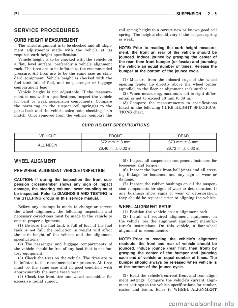
CURB HEIGHT SPECIFICATIONS
VEHICLE FRONT REAR
ALL NEON672 mm68 mm 679 mm68mm
26.46 in.60.32 in. 26.73 in.60.32 in.
WHEEL ALIGNMENT
PRE-WHEEL ALIGNMENT VEHICLE INSPECTION
CAUTION: If during the inspection the front sus-
pension crossmember shows any sign of impact
damage, the steering column lower coupling must
be inspected. Refer to DIAGNOSIS AND TESTING in
the STEERING group in this service manual.
Before any attempt is made to change or correct
the wheel alignment, the following inspection and
necessary corrections must be made to the vehicle to
ensure proper alignment.
(1) Be sure the fuel tank is full of fuel. If the fuel
tank is not full, the reduction in weight will affect
the curb height of the vehicle and the alignment
specifications.
(2) The passenger and luggage compartments of
the vehicle should be free of any load that is not fac-
tory equipment.
(3) Check the tires on the vehicle. The tires are to
be inflated to the recommended air pressure. All tires
must be the same size and in good condition with
approximately the same tread wear.
(4) Check the front tire and wheel assemblies for
excessive radial runout.(5) Inspect all suspension component fasteners for
looseness and torque.
(6) Inspect the lower front ball joints and all steer-
ing linkage for looseness and any sign of wear or
damage.
(7) Inspect the rubber bushings on all the suspen-
sion components for signs of wear or deterioration. If
any bushings show signs of wear or deterioration,
they should be replaced prior to aligning the vehicle.
WHEEL ALIGNMENT SETUP
(1) Position the vehicle on an alignment rack.
(2) Install all required alignment equipment on
the vehicle, per the alignment equipment manufac-
turer's instructions. On this vehicle, a four-wheel
alignment is recommended.
NOTE: Prior to reading the vehicle's alignment
readouts, the front and rear of vehicle should be
jounced. Induce jounce (rear first, then front) by
grasping the center of the bumper and jouncing
each end of vehicle an equal number of times. The
bumper should always be released when vehicle is
at the bottom of the jounce cycle.
(3) Read the vehicle's current front and rear align-
ment settings. Compare the vehicle's current align-
ment settings to the vehicle specifications for camber,
caster and toe-in. Refer to WHEEL ALIGNMENT
PLSUSPENSION 2 - 5
Page 17 of 1285
SPECIFICATIONS in this section of this service
manual group.
(4) If the rear alignment is out of specification,
adjust it first before proceeding to the front.
CAMBER AND CASTER
Front and rear camber and caster settings on this
vehicle are determined at the time the vehicle is
designed, by the location of the vehicle's suspension
components. This is referred to as Net Build. The
result is no required adjustment of camber and
caster after the vehicle is built or when servicing the
suspension components. Thus, when performing a
wheel alignment, caster and camber are not normally
considered adjustable angles. Camber and caster
should be checked to ensure they meet vehicle speci-
fications.
If either front or rear camber is found not to meet
alignment specifications, it can be adjusted using an
available camber adjustment bolt package. Before
installing a camber adjustment bolt package on a
vehicle found to be outside the specifications, inspect
the suspension components for any signs of damage
or bending.
No adjustment can be made to the caster setting
on this vehicle. If the vehicle's caster is not within
alignment specifications, check for damaged suspen-
sion components or body parts.
CAUTION: Do not attempt to adjust the vehicles
wheel alignment by heating or bending any of the
suspension components.
CAMBER ADJUSTMENT BOLT PACKAGE INSTALLATION
NOTE: The following procedure should only be
used on vehicles without the ACR competition
package.
The camber adjustment bolt package contains new
bolts and nuts for attaching the strut clevis bracket
to the steering knuckle. The bolts contained in the
package are slightly undersize allowing for move-
ment between the strut clevis bracket and the steer-
ing knuckle. The movement allowed by the undersize
bolts provide approximately two degrees of camber
adjustment per side of the vehicle. To install and
adjust the camber adjustment bolt package, follow
the procedure below.
CAUTION: There are separate camber adjustment
bolt packages for the front and rear of the vehicle.
Be sure to use the correct package.
(1) Raise the vehicle until its tires are not support-
ing the weight of the vehicle.CAUTION: The knuckle to strut assembly attaching
bolt shanks are serrated and must not be turned
during removal. Remove the nuts while holding the
bolts stationary.
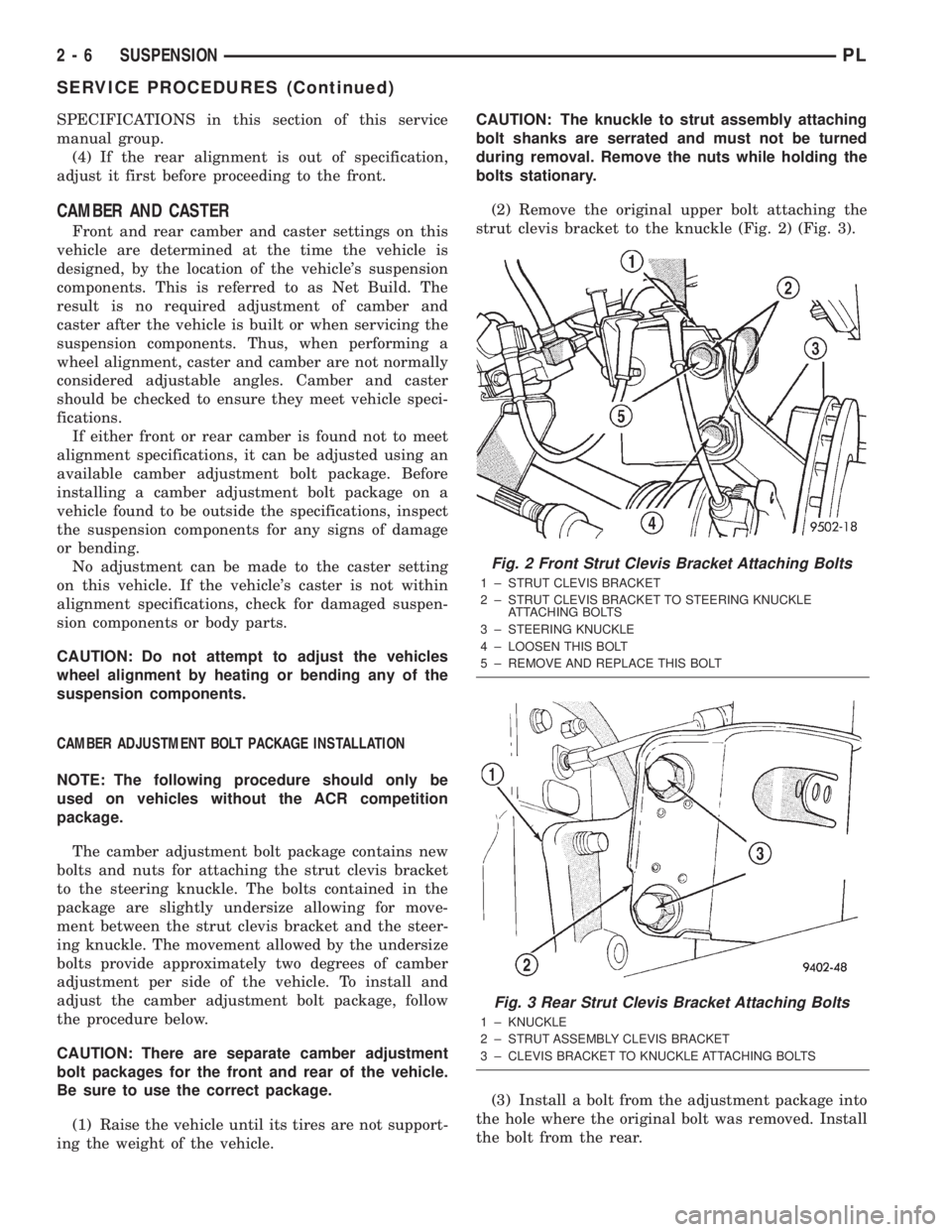
(2) Remove the original upper bolt attaching the
strut clevis bracket to the knuckle (Fig. 2) (Fig. 3).
(3) Install a bolt from the adjustment package into
the hole where the original bolt was removed. Install
the bolt from the rear.
Fig. 2 Front Strut Clevis Bracket Attaching Bolts
1 ± STRUT CLEVIS BRACKET
2 ± STRUT CLEVIS BRACKET TO STEERING KNUCKLE
ATTACHING BOLTS
3 ± STEERING KNUCKLE
4 ± LOOSEN THIS BOLT
5 ± REMOVE AND REPLACE THIS BOLT
Fig. 3 Rear Strut Clevis Bracket Attaching Bolts
1 ± KNUCKLE
2 ± STRUT ASSEMBLY CLEVIS BRACKET
3 ± CLEVIS BRACKET TO KNUCKLE ATTACHING BOLTS
2 - 6 SUSPENSIONPL
SERVICE PROCEDURES (Continued)
Page 56 of 1285
LATERAL ARMS
NOTE: Before proceeding with this procedure,
review SERVICE WARNINGS AND CAUTIONS at the
beginning of REMOVAL AND INSTALLATION in this
section.
Use the following procedure for removal and instal-
lation of one or both lateral arms on one side of the
vehicle's rear suspension.
REMOVAL
(1) Raise the vehicle. Refer to HOISTING in the
LUBRICATION AND MAINTENANCE group for the
proper lifting procedure.
(2) Remove the rear tire and wheel assembly.
(3) Remove the nut, bolt and washers attaching
both lateral arms to the knuckle (Fig. 1).
(4) Remove nut, washer, bolt and wheel alignment
cam attaching the lateral arms to the rear crossmem-
ber (Fig. 1).
(5) Remove the lateral arms from vehicle.
INSTALLATION
NOTE: Both lateral arms when being installed,
must be specifically positioned and orientated on
the vehicle. The lateral arm that has the same size
bushing sleeves on both ends must be mounted on
the forward side of the crossmember and knuckle
with the trimmed outer edge facing rearward. This
front arm is also marked with the word ªFOR-
WARDº. The side of the arm displaying this must
face forward.
The lateral arm with two different size bushing
sleeves must be mounted on the rearward side of
the crossmember and knuckle. Position the smaller
bushing sleeve end at the knuckle and the larger
bushing sleeve end at the rear crossmember (the
larger bushing sleeve is necessary to accommodate
the rear wheel alignment adjustment cam). If the
rear arm is to be mounted on the right side, the
trimmed outer edge must face rearward. If the rear
arm is to be mounted on the left side, the trimmed
outer edge must face forward.
(1) Following the note above, place the forward lat-
eral arm against the leading end of the knuckle, and
then install the short lateral arm mounting bolt with
a washer through the lateral arm and knuckle and
out the trailing end of the knuckle (Fig. 1).
(2) Following the note above, install the small
bushing sleeved end of the rear lateral arm onto the
end of the bolt just installed through the knuckle
(Fig. 1). Install a washer and nut onto the end of the
mounting bolt, but do not completely tighten the bolt
at this time.(3) Install a wheel alignment adjustment cam on
the long arm mounting bolt.
(4) Hold the rear lateral arm up against the cross-
member and install the long mounting bolt with the
adjustment cam through the lateral arm bushing and
rear crossmember (Fig. 1). The bolt must be installed
with the notch in the adjustment cam pointing
straight up.
(5) Position the forward lateral arm against the
rear crossmember hole. Pass the long mounting bolt
through the lateral arm bushing sleeve.
(6) Install a washer and nut onto the end of lateral
arm mounting bolt at the rear crossmember, but do
not completely tighten the bolt at this time.
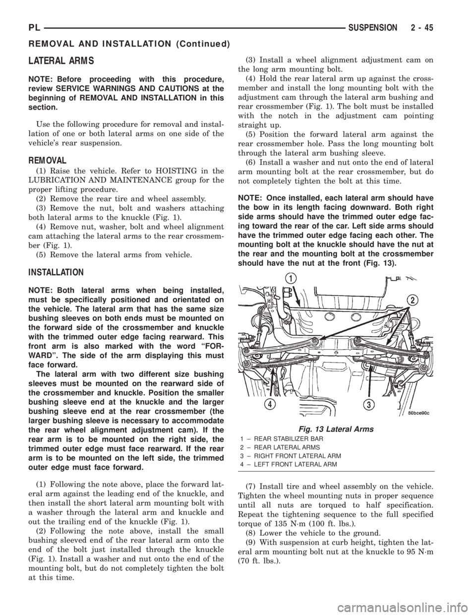
NOTE: Once installed, each lateral arm should have
the bow in its length facing downward. Both right
side arms should have the trimmed outer edge fac-
ing toward the rear of the car. Left side arms should
have the trimmed outer edge facing each other. The
mounting bolt at the knuckle should have the nut at
the rear and the mounting bolt at the crossmember
should have the nut at the front (Fig. 13).
(7) Install tire and wheel assembly on the vehicle.
Tighten the wheel mounting nuts in proper sequence
until all nuts are torqued to half specification.
Repeat the tightening sequence to the full specified
torque of 135 N´m (100 ft. lbs.).
(8) Lower the vehicle to the ground.
(9) With suspension at curb height, tighten the lat-
eral arm mounting bolt nut at the knuckle to 95 N´m
(70 ft. lbs.).
Fig. 13 Lateral Arms
1 ± REAR STABILIZER BAR
2 ± REAR LATERAL ARMS
3 ± RIGHT FRONT LATERAL ARM
4 ± LEFT FRONT LATERAL ARM
PLSUSPENSION 2 - 45
REMOVAL AND INSTALLATION (Continued)
Page 64 of 1285
SHUDDER OR VIBRATION DURING ACCELERATION
(1) A worn or damaged driveshaft inner tripod
joint.
(2) A sticking tripod joint spider assembly (inner
tripod joint only).
(3) Improper wheel alignment. See Wheel Align-
ment in this group for alignment checking and set-
ting procedures and specifications.
VIBRATION AT HIGHWAY SPEEDS
(1) Foreign material (mud, etc.) packed on the
backside of the wheel(s).
(2) Out of balance front tires or wheels. See Group
22, Wheels And Tires for the required balancing pro-
cedure.
(3) Improper tire and/or wheel runout. See Group
22, Wheels And Tires for the required runout check-
ing procedure.
REMOVAL AND INSTALLATION
DRIVESHAFTS
CAUTION: Boot sealing is vital to retain special
lubricants and to prevent foreign contaminants
from entering the C/V joint. Mishandling, such as
allowing the assemblies to dangle unsupported, or
pulling or pushing the ends can cut boots or dam-
age C/V joints. During removal and installation pro-
cedures, always support both ends of the driveshaft
to prevent damage.
REMOVAL
CAUTION: The driveshaft, when installed, acts as a
bolt and secures the front hub/bearing assembly. If
vehicle is to be supported or moved on its wheels
with a driveshaft removed, install a PROPER±SIZED
BOLT AND NUT through front hub. Tighten bolt and
nut to 203 N´m (150 ft. lbs.). This will ensure that
the hub bearing cannot loosen.
(1) Disconnect battery negative cable.
(2) Place transaxle in gated park.
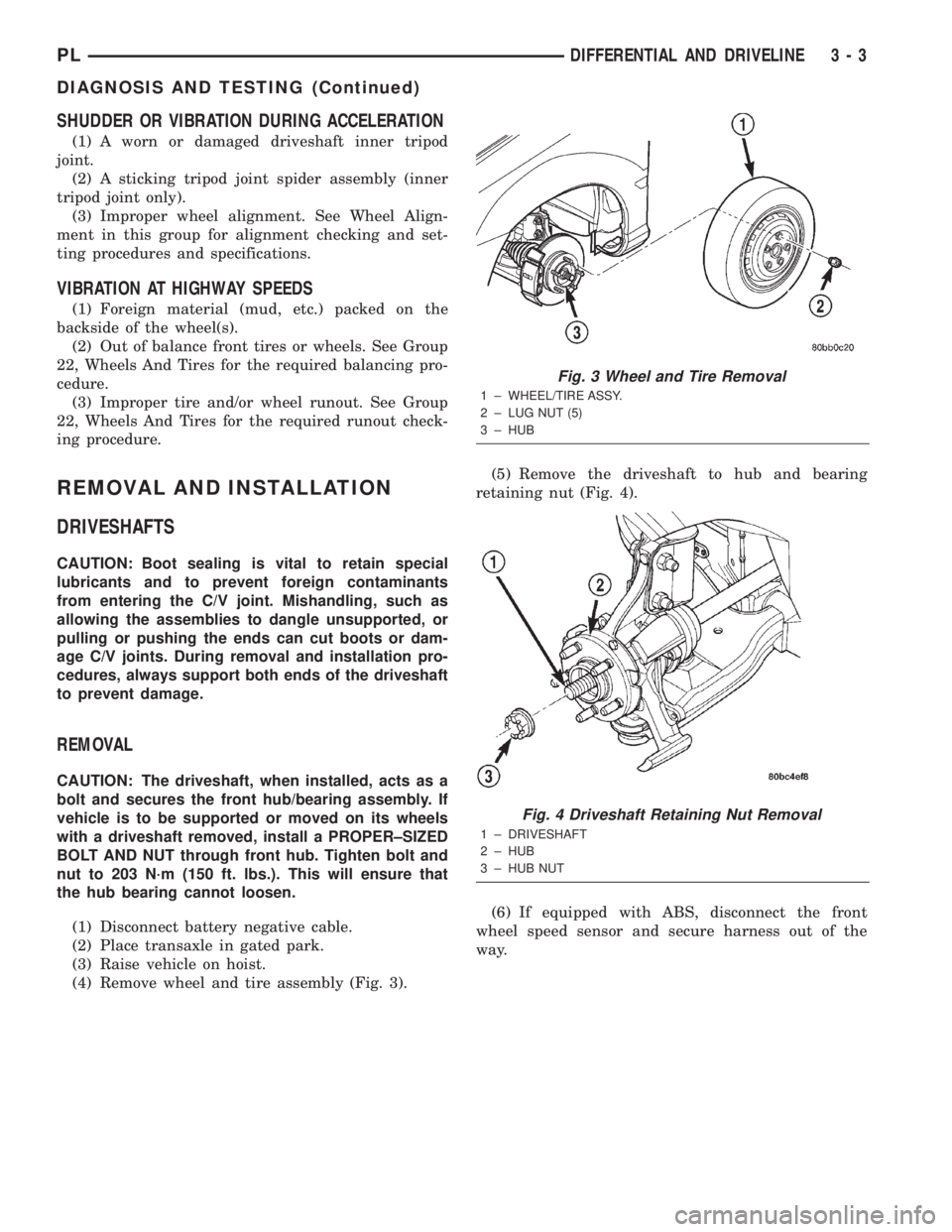
(3) Raise vehicle on hoist.
(4) Remove wheel and tire assembly (Fig. 3).(5) Remove the driveshaft to hub and bearing
retaining nut (Fig. 4).
(6) If equipped with ABS, disconnect the front
wheel speed sensor and secure harness out of the
way.
Fig. 3 Wheel and Tire Removal
1 ± WHEEL/TIRE ASSY.
2 ± LUG NUT (5)
3 ± HUB
Fig. 4 Driveshaft Retaining Nut Removal
1 ± DRIVESHAFT
2 ± HUB
3 ± HUB NUT
PLDIFFERENTIAL AND DRIVELINE 3 - 3
DIAGNOSIS AND TESTING (Continued)
Page 141 of 1285
(4) Insert a brake adjustment tool, or a screw-
driver, through the adjusting hole in support plate
and against the star wheel of the adjuster screw.
Move the handle of tool downward to adjust the
brake drag. Rotate the tire and wheel assembly while
adjusting the adjuster screw. Continue to adjust the
shoes until a slight drag is noticed when the tire and
wheel assembly is rotated.
NOTE: In the event the brake shoes are over-ad-
justed, the adjuster can be backed off using the fol-
lowing step. If not, proceed to step 6.
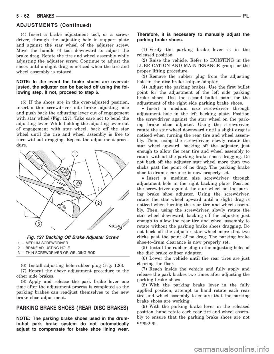
(5) If the shoes are in the over-adjusted position,
insert a thin screwdriver into brake adjusting hole
and push back the adjusting lever out of engagement
with star wheel (Fig. 127). Take care not to bend the
adjusting lever. While holding the adjusting lever out
of engagement with star wheel, back off the star
wheel until the tire and wheel assembly is free to
turn without dragging. Repeat the adjustment proce-
dure.
(6) Install adjusting hole rubber plug (Fig. 126).
(7) Repeat the above adjustment procedure to the
other side brakes.
(8) Apply and release the park brake lever one
time after the adjustment process is completed so the
parking brakes can readjust themselves to the new
brake shoe adjustment.
PARKING BRAKE SHOES (REAR DISC BRAKES)
NOTE: The parking brake shoes used in the drum-
in-hat park brake system do not automatically
adjust to compensate for brake shoe lining wear.Therefore, it is necessary to manually adjust the
parking brake shoes.
(1) Verify the parking brake lever is in the
released position.
(2) Raise the vehicle. Refer to HOISTING in the
LUBRICATION AND MAINTENANCE group for the
proper lifting procedure.
(3) Remove the rubber plug from the adjusting
hole in the disc brake caliper adapter.
(4) Adjust the parking brakes. Use the first bullet
point for the adjustment of the left side parking
brake shoes. Use the second bullet point for the
adjustment of the right side parking brake shoes.
²Insert a medium size screwdriver through
adjustment hole in the left backing plate. Position
the screwdriver against the star wheel on the park-
ing brake shoe adjuster. Using the screwdriver,
rotate the star wheel downward until a slight drag is
noticed when turning the rear tire and wheel assem-
bly. Then, using the screwdriver, slowly rotate the
star wheel upward, backing off the adjuster, just
enough to allow the rear tire and wheel assembly to
rotate without the parking brake shoes dragging. Do
not back off the adjuster star wheel more than two
clicks past the point of no drag. The parking brake
shoe-to-drum clearance is now properly set.
²Insert a medium size screwdriver through
adjustment hole in the right backing plate. Position
the screwdriver against the star wheel on the park-
ing brake shoe adjuster. Using the screwdriver,
rotate the star wheel upward until a slight drag is
noticed when turning the rear tire and wheel assem-
bly. Then, using the screwdriver, slowly rotate the
star wheel downward, backing off the adjuster, just
enough to allow the rear tire and wheel assembly to
rotate without the parking brake shoes dragging. Do
not back off the adjuster star wheel more that two
clicks past the point of no drag. The parking brake
shoe-to-drum clearance is now properly set.
(5) Install the rubber plug in the adjusting holes of
the disc brake caliper adapter.
(6) Lower the vehicle until the rear tires are just
clearing the floor.
(7) Reach inside the vehicle and fully apply and
release the park brakes two times after adjusting the
parking brake shoes.
(8) With the parking brake lever in the fully
applied position, attempt to hand rotate each rear
tire and wheel assembly to ensure that the parking
brake shoes are working.
(9) With the parking brake lever in the released
position, hand rotate each rear tire and wheel assem-
bly to ensure that the parking brake shoes are not
dragging.
Fig. 127 Backing Off Brake Adjuster Screw
1 ± MEDIUM SCREWDRIVER
2 ± BRAKE ADJUSTING HOLE
3 ± THIN SCREWDRIVER OR WELDING ROD
5 - 62 BRAKESPL
ADJUSTMENTS (Continued)
Page 142 of 1285
SPECIFICATIONS
BRAKE FLUID
The brake fluid used in this vehicle must conform
to DOT 3 specifications and SAE J1703 standards.
No other type of brake fluid is recommended or
approved for usage in the vehicle brake system. Use
only Mopar brake fluid or an equivalent from a
tightly sealed container.
CAUTION: Never use reclaimed brake fluid or fluid
from an container which has been left open. An
open container will absorb moisture from the air
and contaminate the fluid.
CAUTION: Never use any type of a petroleum-
based fluid in the brake hydraulic system. Use of
such type fluids will result in seal damage of the
vehicle brake hydraulic system causing a failure of
the vehicle brake system. Petroleum based fluids
would be items such as engine oil, transmission
fluid, power steering fluid, etc.
BRAKE ACTUATION SYSTEM
ACTUATION:
Vacuum Operated Power Brakes.....Standard
Hydraulic System.......Dual-Diagonally Split
BRAKE PEDAL:
Pedal Ratio..........................3.41
POWER BRAKE BOOSTER:
Make/Type..................Bosch/Vacuum
Mounting Studs.................. M8x1.25
Diaphragm Size/Type........ 205mmTandem
MASTER CYLINDER ASSEMBLY:
Type ........................Dual Tandem
Body Material...........Anodized Aluminum
Reservoir Material.............Polypropelene
MASTER CYLINDER BORE STROKE AND
SPLIT:
NonABS ..............22.23 mm x 34.0 mm
(0.875 in. x 1.34 in.)
ABS . . 23.82 mm x 34.0 mm (0.937 in. x 1.34 in.)
Displacement Split.................. 50/50MASTER CYLINDER FLUID OUTLET PORTS:
Tube Fitting Type...... SAE45ÉInverted Flare
W/ABS - Primary Tube Nut
Thread........................7/16 in.±24
W/ABS - Secondary Tube Nut
Thread........................ 3/8in.±24
W/O ABS - All Tube Nut Threads....7/16 in.±24
ABS HYDRAULIC CONTROL UNIT:
Hydraulic Tube Fitting
Type................ SAE45ÉInverted Flare
All Tube Nut Threads............7/16 in.±24
PROPORTIONING VALVE:
Material.......................Aluminum
Function.....Hydraulic Pressure Proportioning
BRAKE FASTENER TORQUE SPECIFICATIONS
DESCRIPTION TORQUE
BRAKE TUBES:
Tube Nuts............... 17N´m(145 in. lbs.)
MASTER CYLINDER:
Mounting Nuts.......... 28N´m(250 in. lbs.)
POWER BRAKE BOOSTER:
Mounting Nuts.......... 34N´m(300 in. lbs.)
DISC BRAKE CALIPER:
Caliper Banjo Bolt......... 48N´m(35ft.lbs.)
Guide Pin Bolts.......... 22N´m(192 in. lbs.)
Bleeder Screw........... 15N´m(125 in. lbs.)
WHEEL CYLINDER (REAR):
Mounting Bolts.......... 13N´m(115in.lbs.)
Bleeder Screw............ 10N´m(80in.lbs.)
DRUM BRAKE SHOE SUPPORT PLATE
(REAR):
Mounting Bolts........... 75N´m(55ft.lbs.)
DISC BRAKE ADAPTER (REAR):
Mounting Bolts........... 75N´m(55ft.lbs.)
HUB AND BEARING (REAR):
Retaining Nut.......... 217N´m(160 ft. lbs.)
PARKING BRAKE:
Lever Mounting Nuts..... 28N´m(250 in. lbs.)
TIRE AND WHEEL:
Wheel Mounting Nut...........109±150 N´m
(80±110 ft. lbs.)
INTEGRATED CONTROL UNIT:
Mounting Bolts........... 11N´m(97in.lbs.)
CAB Mounting bolts........ 2N´m(17in.lbs.)
Bracket-to-Frame Rail Bolts.......... 23N´m
(200 in. lbs.)
WHEEL SPEED SENSOR:
Head Mounting bolt...... 12N´m(105 in. lbs.)
PLBRAKES 5 - 63
Page 148 of 1285
AMBER ABS WARNING LAMP
The amber ABS warning lamp is located in the
instrument cluster. The purpose of the warning lamp
is discussed in detail below.
When the ignition key is turned to the ON posi-
tion, the amber ABS warning lamp is lit until the
CAB completes its self-tests and turns off the lamp
(approximately 4 seconds). The amber ABS warning
lamp will illuminate when the CAB detects a condi-
tion that results in the shutdown of ABS function.
The CAB sends a message to the mechanical instu-
ment cluster (MIC) instructing it to turn on the
amber ABS warning lamp.
Under most conditions, when the amber ABS warn-
ing lamp is on, only the ABS function of the brake
system is affected; The electronic brake distribution
(EBD), the base brake system and the ability to stop
the vehicle are not affected.
WHEEL SPEED SENSOR (WSS)
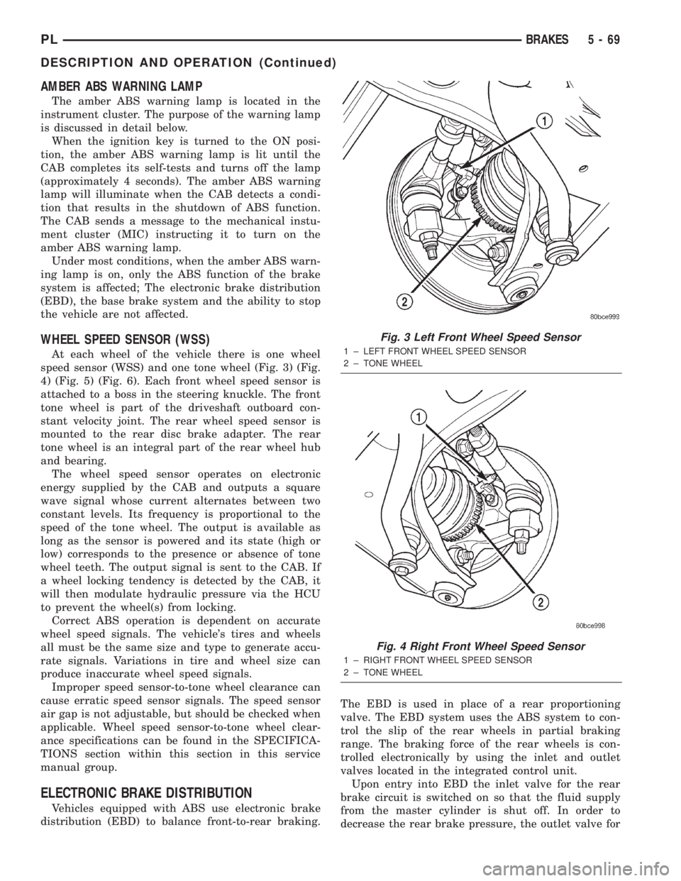
At each wheel of the vehicle there is one wheel
speed sensor (WSS) and one tone wheel (Fig. 3) (Fig.
4) (Fig. 5) (Fig. 6). Each front wheel speed sensor is
attached to a boss in the steering knuckle. The front
tone wheel is part of the driveshaft outboard con-
stant velocity joint. The rear wheel speed sensor is
mounted to the rear disc brake adapter. The rear
tone wheel is an integral part of the rear wheel hub
and bearing.
The wheel speed sensor operates on electronic
energy supplied by the CAB and outputs a square
wave signal whose current alternates between two
constant levels. Its frequency is proportional to the
speed of the tone wheel. The output is available as
long as the sensor is powered and its state (high or
low) corresponds to the presence or absence of tone
wheel teeth. The output signal is sent to the CAB. If
a wheel locking tendency is detected by the CAB, it
will then modulate hydraulic pressure via the HCU
to prevent the wheel(s) from locking.
Correct ABS operation is dependent on accurate
wheel speed signals. The vehicle's tires and wheels
all must be the same size and type to generate accu-
rate signals. Variations in tire and wheel size can
produce inaccurate wheel speed signals.
Improper speed sensor-to-tone wheel clearance can
cause erratic speed sensor signals. The speed sensor
air gap is not adjustable, but should be checked when
applicable. Wheel speed sensor-to-tone wheel clear-
ance specifications can be found in the SPECIFICA-
TIONS section within this section in this service
manual group.
ELECTRONIC BRAKE DISTRIBUTION
Vehicles equipped with ABS use electronic brake
distribution (EBD) to balance front-to-rear braking.The EBD is used in place of a rear proportioning
valve. The EBD system uses the ABS system to con-
trol the slip of the rear wheels in partial braking
range. The braking force of the rear wheels is con-
trolled electronically by using the inlet and outlet
valves located in the integrated control unit.
Upon entry into EBD the inlet valve for the rear
brake circuit is switched on so that the fluid supply
from the master cylinder is shut off. In order to
decrease the rear brake pressure, the outlet valve for
Fig. 3 Left Front Wheel Speed Sensor
1 ± LEFT FRONT WHEEL SPEED SENSOR
2 ± TONE WHEEL
Fig. 4 Right Front Wheel Speed Sensor
1 ± RIGHT FRONT WHEEL SPEED SENSOR
2 ± TONE WHEEL
PLBRAKES 5 - 69
DESCRIPTION AND OPERATION (Continued)
Page 287 of 1285
SPEED CONTROL SERVO-PCM OUTPUT
DESCRIPTION
The servo unit consists of a solenoid valve body,
and a vacuum chamber. The solenoid valve body con-
tains three solenoids:
²Vacuum
²Vent
²Dump
The vacuum chamber contains a diaphragm with a
cable attached to control the throttle linkage.
OPERATION
The PCM controls the solenoid valve body. The
solenoid valve body controls the application and
release of vacuum to the diaphragm of the vacuum
servo. The servo unit cannot be repaired and is ser-
viced only as a complete assembly.
Power is supplied to the servo's by the PCM
through the brake switch. The PCM controls the
ground path for the vacuum and vent solenoids.
The dump solenoid is energized anytime it receives
power. If power to the dump solenoid is interrupted,
the solenoid dumps vacuum in the servo. This pro-
vides a safety backup to the vent and vacuum sole-
noids.
The vacuum and vent solenoids must be grounded
at the PCM to operate. When the PCM grounds the
vacuum servo solenoid, the solenoid allows vacuum
to enter the servo and pull open the throttle plate
using the cable. When the PCM breaks the ground,
the solenoid closes and no more vacuum is allowed to
enter the servo. The PCM also operates the vent sole-
noid via ground. The vent solenoid opens and closes a
passage to bleed or hold vacuum in the servo as
required.
The PCM duty cycles the vacuum and vent sole-
noids to maintain the set speed, or to accelerate and
decelerate the vehicle. To increase throttle opening,
the PCM grounds the vacuum and vent solenoids. To
decrease throttle opening, the PCM removes the
grounds from the vacuum and vent solenoids. When
the brake is released, if vehicle speed exceeds 25
mph to resume, 30 mph to set, and the RES/ACCEL
switch has been depressed, ground for the vent and
vacuum circuits is restored.
SPEED CONTROL SWITCHESÐPCM INPUT
Description
There are two separate switch pods that operate
the speed control system. The steering-wheel-
mounted switches use multiplexed circuits to provide
inputs to the PCM for ON, OFF, RESUME, ACCEL-
ERATE, SET, DECEL and CANCEL modes. Refer tothe owner's manual for more information on speed
control switch functions and setting procedures.
The individual switches cannot be repaired. If one
switch fails, the entire switch module must be
replaced.
Operation
When speed control is selected by depressing the
ON, OFF switch, the PCM allows a set speed to be
stored in RAM for speed control. To store a set speed,
depress the SET switch while the vehicle is moving
at a speed between 25 and 85 mph. In order for the
speed control to engage, the brakes cannot be
applied, nor can the gear selector be indicating the
transmission is in Park or Neutral.
Once the speed control has been disengaged,
depressing the ACCEL switch restores the vehicle to
the target speed that was stored in the PCM's RAM.
NOTE: Depressing the OFF switch will erase the
set speed stored in the PCM's RAM.
If, while the speed control is engaged, the driver
wishes to increase vehicle speed, the PCM is pro-
grammed for an acceleration feature. With the
ACCEL switch held closed, the vehicle accelerates
slowly to the desired speed. The new target speed is
stored in the RAM when the ACCEL switch is
released. The PCM also has a ªtap-upº feature in
which vehicle speed increases at a rate of approxi-
mately 2 mph for each momentary switch activation
of the ACCEL switch.
The PCM also provides a means to decelerate with-
out disengaging speed control. To decelerate from an
existing recorded target speed, depress and hold the
COAST switch until the desired speed is reached.
Then release the switch. The ON, OFF switch oper-
ates two components: the PCM's ON, OFF input, and
the battery voltage to the brake switch, which powers
the speed control servo.
Multiplexing
The PCM sends out 5 volts through a fixed resistor
and monitors the voltage change between the fixed
resistor and the switches. If none of the switches are
depressed, the PCM will measure 5 volts at the sen-
sor point (open circuit). If a switch with no resistor is
closed, the PCM will measure 0 volts (grounded cir-
cuit). Now, if a resistor is added to a switch, then the
PCM will measure some voltage proportional to the
size of the resistor. By adding a different resistor to
each switch, the PCM will see a different voltage
depending on which switch is pushed.
8H - 2 VEHICLE SPEED CONTROL SYSTEMPL
DESCRIPTION AND OPERATION (Continued)