2000 DODGE NEON heater core
[x] Cancel search: heater corePage 182 of 1285
protection. MopartAntifreeze or the equivalent is
recommended for best engine cooling without corro-
sion. When mixed only to a freeze point of -37ÉC
(-35ÉF) to -59ÉC (-50ÉF). If it looses color or becomes
contaminated, drain, flush, and replace with fresh
properly mixed solution.
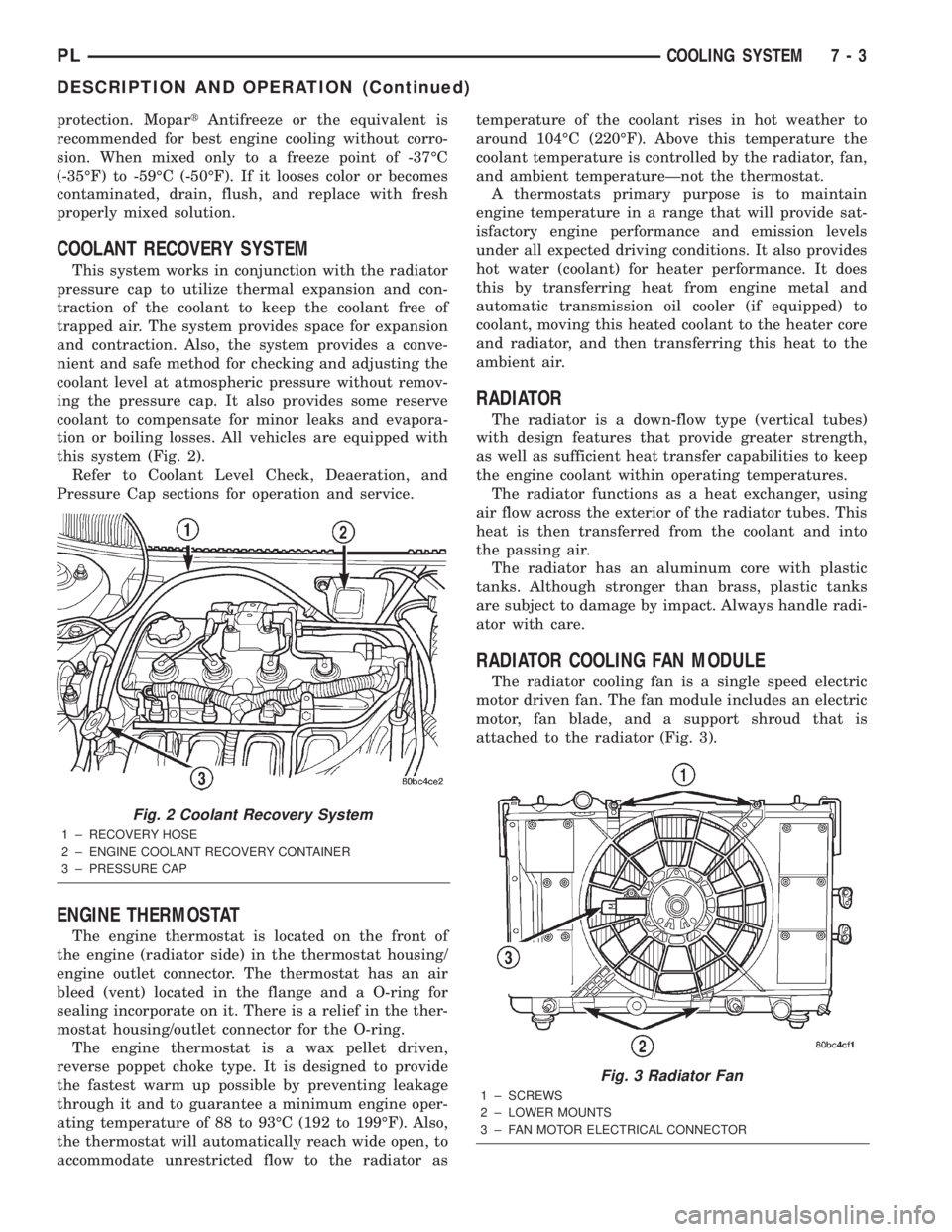
COOLANT RECOVERY SYSTEM
This system works in conjunction with the radiator
pressure cap to utilize thermal expansion and con-
traction of the coolant to keep the coolant free of
trapped air. The system provides space for expansion
and contraction. Also, the system provides a conve-
nient and safe method for checking and adjusting the
coolant level at atmospheric pressure without remov-
ing the pressure cap. It also provides some reserve
coolant to compensate for minor leaks and evapora-
tion or boiling losses. All vehicles are equipped with
this system (Fig. 2).
Refer to Coolant Level Check, Deaeration, and
Pressure Cap sections for operation and service.
ENGINE THERMOSTAT
The engine thermostat is located on the front of
the engine (radiator side) in the thermostat housing/
engine outlet connector. The thermostat has an air
bleed (vent) located in the flange and a O-ring for
sealing incorporate on it. There is a relief in the ther-
mostat housing/outlet connector for the O-ring.
The engine thermostat is a wax pellet driven,
reverse poppet choke type. It is designed to provide
the fastest warm up possible by preventing leakage
through it and to guarantee a minimum engine oper-
ating temperature of 88 to 93ÉC (192 to 199ÉF). Also,
the thermostat will automatically reach wide open, to
accommodate unrestricted flow to the radiator astemperature of the coolant rises in hot weather to
around 104ÉC (220ÉF). Above this temperature the
coolant temperature is controlled by the radiator, fan,
and ambient temperatureÐnot the thermostat.
A thermostats primary purpose is to maintain
engine temperature in a range that will provide sat-
isfactory engine performance and emission levels
under all expected driving conditions. It also provides
hot water (coolant) for heater performance. It does
this by transferring heat from engine metal and
automatic transmission oil cooler (if equipped) to
coolant, moving this heated coolant to the heater core
and radiator, and then transferring this heat to the
ambient air.
RADIATOR
The radiator is a down-flow type (vertical tubes)
with design features that provide greater strength,
as well as sufficient heat transfer capabilities to keep
the engine coolant within operating temperatures.
The radiator functions as a heat exchanger, using
air flow across the exterior of the radiator tubes. This
heat is then transferred from the coolant and into
the passing air.
The radiator has an aluminum core with plastic
tanks. Although stronger than brass, plastic tanks
are subject to damage by impact. Always handle radi-
ator with care.
RADIATOR COOLING FAN MODULE
The radiator cooling fan is a single speed electric
motor driven fan. The fan module includes an electric
motor, fan blade, and a support shroud that is
attached to the radiator (Fig. 3).
Fig. 2 Coolant Recovery System
1 ± RECOVERY HOSE
2 ± ENGINE COOLANT RECOVERY CONTAINER
3 ± PRESSURE CAP
Fig. 3 Radiator Fan
1 ± SCREWS
2 ± LOWER MOUNTS
3 ± FAN MOTOR ELECTRICAL CONNECTOR
PLCOOLING SYSTEM 7 - 3
DESCRIPTION AND OPERATION (Continued)
Page 184 of 1285
RADIATOR HOSES AND CLAMPS
WARNING: IF VEHICLE HAS BEEN RUN RECENTLY,
WAIT 15 MINUTES BEFORE WORKING ON VEHI-
CLE. RELIEVE PRESSURE BY PLACING A SHOP
TOWEL OVER THE CAP AND WITHOUT PUSHING
DOWN ROTATE IT COUNTERCLOCKWISE TO THE
FIRST STOP. ALLOW FLUIDS TO ESCAPE
THROUGH THE OVERFLOW TUBE AND WHEN THE
SYSTEM STOPS PUSHING OUT COOLANT AND
STEAM AND THE PRESSURE DROPS CONTINUE
SERVICE.
WARNING: CONSTANT TENSION HOSE CLAMPS
ARE USED ON MOST COOLING SYSTEM HOSES.
WHEN REMOVING OR INSTALLING, USE ONLY
TOOLS DESIGNED FOR SERVICING THIS TYPE OF
CLAMP. ALWAYS WEAR SAFETY GLASSES WHEN
SERVICING CONSTANT TENSION CLAMPS.
CAUTION: A number or letter is stamped into the
tongue of constant tension clamps. If replacement
is necessary, use only a original equipment clamp
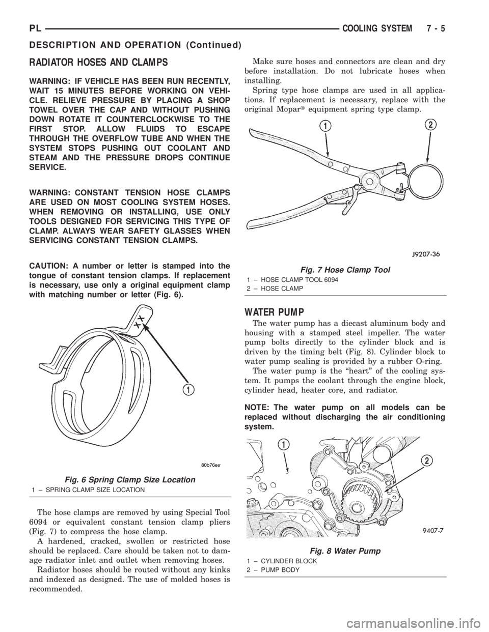
with matching number or letter (Fig. 6).
The hose clamps are removed by using Special Tool
6094 or equivalent constant tension clamp pliers
(Fig. 7) to compress the hose clamp.
A hardened, cracked, swollen or restricted hose
should be replaced. Care should be taken not to dam-
age radiator inlet and outlet when removing hoses.
Radiator hoses should be routed without any kinks
and indexed as designed. The use of molded hoses is
recommended.Make sure hoses and connectors are clean and dry
before installation. Do not lubricate hoses when
installing.
Spring type hose clamps are used in all applica-
tions. If replacement is necessary, replace with the
original Mopartequipment spring type clamp.
WATER PUMP
The water pump has a diecast aluminum body and
housing with a stamped steel impeller. The water
pump bolts directly to the cylinder block and is
driven by the timing belt (Fig. 8). Cylinder block to
water pump sealing is provided by a rubber O-ring.
The water pump is the ªheartº of the cooling sys-
tem. It pumps the coolant through the engine block,
cylinder head, heater core, and radiator.
NOTE: The water pump on all models can be
replaced without discharging the air conditioning
system.
Fig. 6 Spring Clamp Size Location
1 ± SPRING CLAMP SIZE LOCATION
Fig. 7 Hose Clamp Tool
1 ± HOSE CLAMP TOOL 6094
2 ± HOSE CLAMP
Fig. 8 Water Pump
1 ± CYLINDER BLOCK
2 ± PUMP BODY
PLCOOLING SYSTEM 7 - 5
DESCRIPTION AND OPERATION (Continued)
Page 185 of 1285
AUTOMATIC TRANSMISSION OIL COOLER
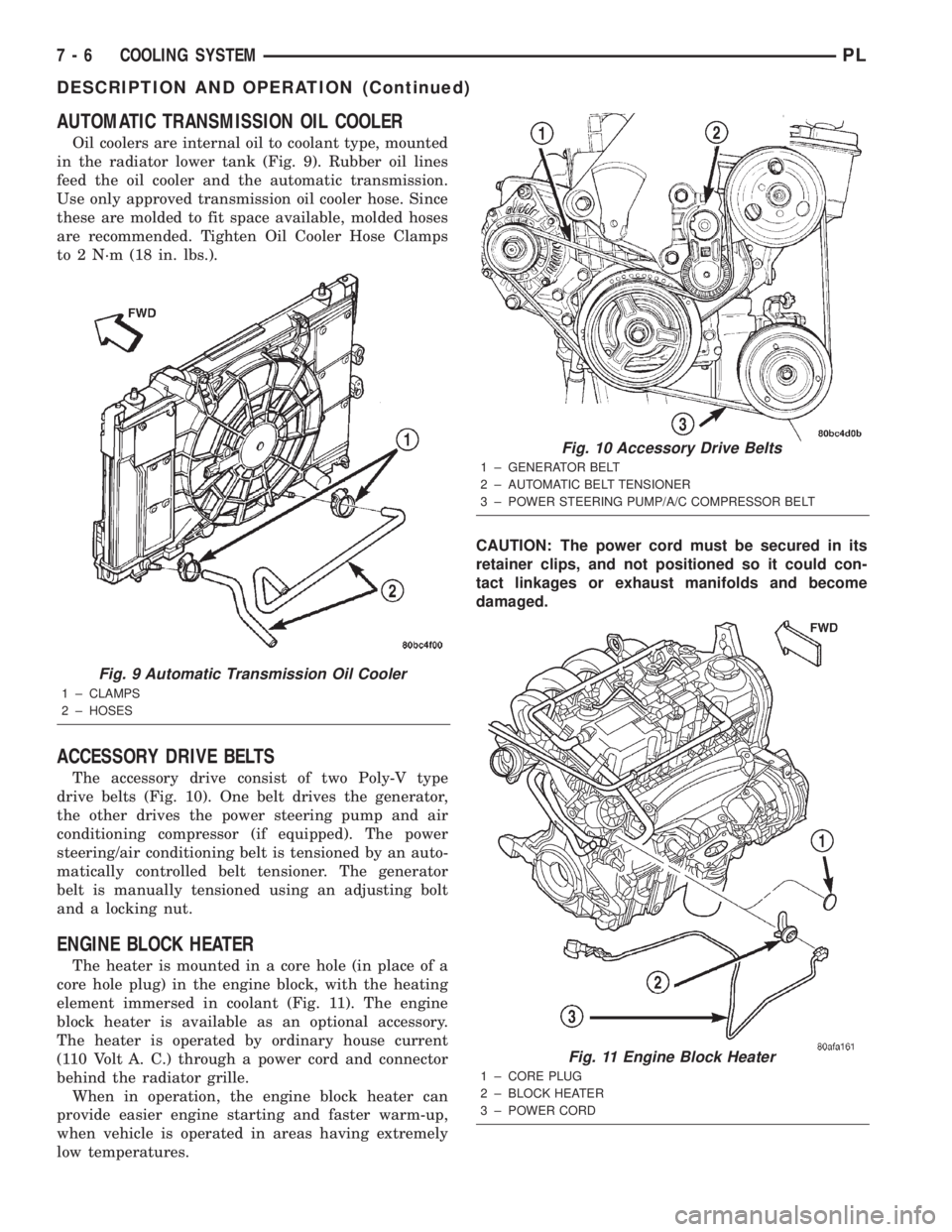
Oil coolers are internal oil to coolant type, mounted
in the radiator lower tank (Fig. 9). Rubber oil lines
feed the oil cooler and the automatic transmission.
Use only approved transmission oil cooler hose. Since
these are molded to fit space available, molded hoses
are recommended. Tighten Oil Cooler Hose Clamps
to 2 N´m (18 in. lbs.).
ACCESSORY DRIVE BELTS
The accessory drive consist of two Poly-V type
drive belts (Fig. 10). One belt drives the generator,
the other drives the power steering pump and air
conditioning compressor (if equipped). The power
steering/air conditioning belt is tensioned by an auto-
matically controlled belt tensioner. The generator
belt is manually tensioned using an adjusting bolt
and a locking nut.
ENGINE BLOCK HEATER
The heater is mounted in a core hole (in place of a
core hole plug) in the engine block, with the heating
element immersed in coolant (Fig. 11). The engine
block heater is available as an optional accessory.
The heater is operated by ordinary house current
(110 Volt A. C.) through a power cord and connector
behind the radiator grille.
When in operation, the engine block heater can
provide easier engine starting and faster warm-up,
when vehicle is operated in areas having extremely
low temperatures.CAUTION: The power cord must be secured in its
retainer clips, and not positioned so it could con-
tact linkages or exhaust manifolds and become
damaged.
Fig. 9 Automatic Transmission Oil Cooler
1 ± CLAMPS
2 ± HOSES
Fig. 10 Accessory Drive Belts
1 ± GENERATOR BELT
2 ± AUTOMATIC BELT TENSIONER
3 ± POWER STEERING PUMP/A/C COMPRESSOR BELT
Fig. 11 Engine Block Heater
1 ± CORE PLUG
2 ± BLOCK HEATER
3 ± POWER CORD
7 - 6 COOLING SYSTEMPL
DESCRIPTION AND OPERATION (Continued)
Page 188 of 1285
CONDITION POSSIBLE CAUSE CORRECTION
16. Electric cooling fan not
operating properly.16. Check electric fan operation and
repair as necessary.
17. Cylinder head gasket leaking. 17. Check cylinder head gasket for
leaks. Refer to testing cooling
system for leaks. For repairs, refer
to Group 9, Engine.
18. Heater core leaking. 18. Check heater core for leaks.
Refer to Group 24, Heating and Air
Conditioning and repair as
necessary.
TEMPERATURE GAUGE READING
IS INCONSISTENT (FLUCTUATES,
CYCLES OR IS ERRATIC)1. The gauge may cycle up and
down. This is due to the cycling of
the electric radiator fan.1. A normal condition. No correction
is necessary. If gauge cycling is
going into the hot zone, check
electric fan operation and repair as
necessary. Refer to procedure in
this section.
2. During cold weather operation
with the heater blower in the high
position, the gauge reading may
drop slightly.2. A normal condition. No correction
is necessary.
3, Temperature gauge or engine
mounted gauge sensor is defective
or shorted.3. Check operation of gauge and
repair as necessary. Refer to Group
8E, Instrument Panel and Gauges.
4. Gauge reading rises when
vehicle is brought to a stop after
heavy use (engine still running).4. A normal condition. No correction
is necessary. The gauge should
return to normal range after vehicle
is driven.
5. Gauge reading high after
restarting a warmed-up (hot)
engine.5. A normal condition. No correction
is necessary. The gauge should
return to normal range after a few
minutes of engine operation.
6. Coolant level low in radiator (air
will build up in the cooling system
causing the thermostat to open
late).6. Check and correct coolant leaks.
Refer to Testing Cooling System For
Leaks in the section.
7. Cylinder head gasket leaking
allowing exhaust gas to enter
cooling system. This will cause
thermostat to open late.7. (a) Check for cylinder head
gasket leaks with a commercially
available Block Leak Tester. Repair
as necessary.
(b) Check for coolant in the engine
oil. Inspect for white steam emitting
from exhaust system. Repair as
necessary.
8. Water pump impeller loose on
shaft.8. Check water pump and replace
as necessary. Refer to Water Pump
in this section.
9. Loose drive belt (water pump
slipping).9. Check drive belt and correct as
necessary.
PLCOOLING SYSTEM 7 - 9
DIAGNOSIS AND TESTING (Continued)
Page 191 of 1285
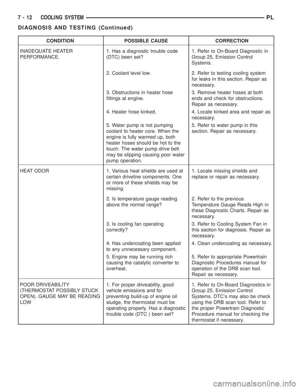
CONDITION POSSIBLE CAUSE CORRECTION
INADEQUATE HEATER
PERFORMANCE.1. Has a diagnostic trouble code
(DTC) been set?1. Refer to On-Board Diagnostic in
Group 25, Emission Control
Systems.
2. Coolant level low. 2. Refer to testing cooling system
for leaks in this section. Repair as
necessary.
3. Obstructions in heater hose
fittings at engine.3. Remove heater hoses at both
ends and check for obstructions.
Repair as necessary.
4. Heater hose kinked. 4. Locate kinked area and repair as
necessary.
5. Water pump is not pumping
coolant to heater core. When the
engine is fully warmed up, both
heater hoses should be hot to the
touch. The water pump drive belt
may be slipping causing poor water
pump operation.5. Refer to water pump in this
section. Repair as necessary.
HEAT ODOR 1. Various heat shields are used at
certain driveline components. One
or more of these shields may be
missing.1. Locate missing shields and
replace or repair as necessary.
2. Is temperature gauge reading
above the normal range?2. Refer to the previous
Temperature Gauge Reads High in
these Diagnostic Charts. Repair as
necessary.
3. Is cooling fan operating
correctly?3. Refer to Cooling System Fan in
this section for diagnosis. Repair as
necessary.
4. Has undercoating been applied
to any unnecessary component.4. Clean undercoating as necessary.
5. Engine may be running rich
causing the catalytic converter to
overheat.5. Refer to appropriate Powertrain
Diagnostic Procedures manual for
operation of the DRB scan tool.
Repair as necessary.
POOR DRIVEABILITY
(THERMOSTAT POSSIBLY STUCK
OPEN). GAUGE MAY BE READING
LOW1. For proper driveability, good
vehicle emissions and for
preventing build-up of engine oil
sludge, the thermostat must be
operating properly. Has a diagnostic
trouble code (DTC ) been set?1. Refer to On-Board Diagnostics in
Group 25, Emission Control
Systems. DTC's may also be check
using the DRB scan tool. Refer to
the proper Powertrain Diagnostic
Procedure manual for checking the
thermostat if necessary.
7 - 12 COOLING SYSTEMPL
DIAGNOSIS AND TESTING (Continued)
Page 196 of 1285
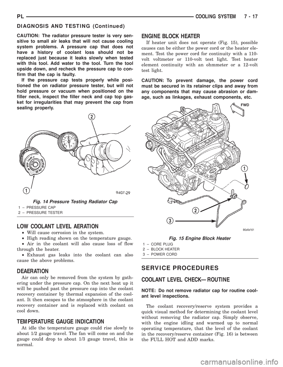
CAUTION: The radiator pressure tester is very sen-
sitive to small air leaks that will not cause cooling
system problems. A pressure cap that does not
have a history of coolant loss should not be
replaced just because it leaks slowly when tested
with this tool. Add water to the tool. Turn the tool
upside down, and recheck the pressure cap to con-
firm that the cap is faulty.
If the pressure cap tests properly while posi-
tioned the on radiator pressure tester, but will not
hold pressure or vacuum when positioned on the
filler neck, inspect the filler neck and cap top gas-
ket for irregularities that may prevent the cap from
sealing properly.
LOW COOLANT LEVEL AERATION
²Will cause corrosion in the system.
²High reading shown on the temperature gauge.
²Air in the coolant will also cause loss of flow
through the heater.
²Exhaust gas leaks into the coolant can also
cause the above problems.
DEAERATION
Air can only be removed from the system by gath-
ering under the pressure cap. On the next heat up it
will be pushed past the pressure cap into the coolant
recovery container by thermal expansion of the cool-
ant. It then escapes to the atmosphere in the coolant
recovery container and is replaced with coolant on
cool down.
TEMPERATURE GAUGE INDICATION
At idle the temperature gauge could rise slowly to
about 1/2 gauge travel. The fan will come on and the
gauge could drop to about 1/3 gauge travel, this is
normal.
ENGINE BLOCK HEATER
If heater unit does not operate (Fig. 15), possible
causes can be either the power cord or the heater ele-
ment. Test the power cord for continuity with a 110-
volt voltmeter or 110-volt test light. Test heater
element continuity with an ohmmeter or a 12-volt
test light.
CAUTION: To prevent damage, the power cord
must be secured in its retainer clips and away from
any components that may cause abrasion or dam-
age, such as linkages, exhaust components, etc.
SERVICE PROCEDURES
COOLANT LEVEL CHECKÐROUTINE
NOTE: Do not remove radiator cap for routine cool-
ant level inspections.
The coolant recovery/reserve system provides a
quick visual method for determining the coolant level
without removing the radiator cap. Simply observe,
with the engine idling and warmed up to normal
operating temperature, that the level of the coolant
in the recovery/reserve container (Fig. 16) is between
the FULL HOT and ADD marks.
Fig. 14 Pressure Testing Radiator Cap
1 ± PRESSURE CAP
2 ± PRESSURE TESTER
Fig. 15 Engine Block Heater
1 ± CORE PLUG
2 ± BLOCK HEATER
3 ± POWER CORD
PLCOOLING SYSTEM 7 - 17
DIAGNOSIS AND TESTING (Continued)
Page 199 of 1285
(4) Rotate pump by hand to check for freedom of
movement.
(5) Install rear timing belt cover and camshaft
sprocket.
(6) Install timing belt tensioner and timing belt.
Refer to Group 9, Engine for procedure.
(7) Install right engine mount bracket. Refer to
Group 9, Engine for procedure.
(8) Install upper and lower torque isolator struts.
Refer to Group 9, Engine for procedure.
(9) Fill cooling system. Refer to procedures in this
section.
(10) Install accessory drive belts. Refer to proce-
dure in this section.
(11) Perform camshaft and crankshaft timing
relearn procedure as follows:
²Connect the DRB scan tool to the data link
(diagnostic) connector. This connector is located in
the passenger compartment; at the lower edge of
instrument panel; near the steering column.
²Turn the ignition switch on and access the ªmis-
cellaneousº screen.
²Select ªre-learn cam/crankº option and follow
directions on DRB screen.
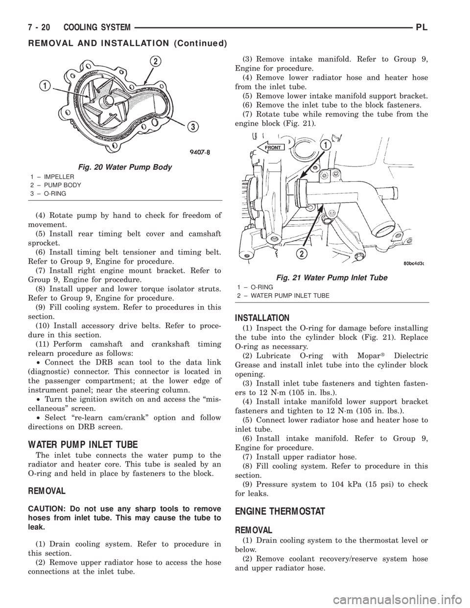
WATER PUMP INLET TUBE
The inlet tube connects the water pump to the
radiator and heater core. This tube is sealed by an
O-ring and held in place by fasteners to the block.
REMOVAL
CAUTION: Do not use any sharp tools to remove
hoses from inlet tube. This may cause the tube to
leak.
(1) Drain cooling system. Refer to procedure in
this section.
(2) Remove upper radiator hose to access the hose
connections at the inlet tube.(3) Remove intake manifold. Refer to Group 9,
Engine for procedure.
(4) Remove lower radiator hose and heater hose
from the inlet tube.
(5) Remove lower intake manifold support bracket.
(6) Remove the inlet tube to the block fasteners.
(7) Rotate tube while removing the tube from the
engine block (Fig. 21).
INSTALLATION
(1) Inspect the O-ring for damage before installing
the tube into the cylinder block (Fig. 21). Replace
O-ring as necessary.
(2) Lubricate O-ring with MopartDielectric
Grease and install inlet tube into the cylinder block
opening.
(3) Install inlet tube fasteners and tighten fasten-
ers to 12 N´m (105 in. lbs.).
(4) Install intake manifold lower support bracket
fasteners and tighten to 12 N´m (105 in. lbs.).
(5) Connect lower radiator hose and heater hose to
inlet tube.
(6) Install intake manifold. Refer to Group 9,
Engine for procedure.
(7) Install upper radiator hose.
(8) Fill cooling system. Refer to procedure in this
section.
(9) Pressure system to 104 kPa (15 psi) to check
for leaks.
ENGINE THERMOSTAT
REMOVAL
(1) Drain cooling system to the thermostat level or
below.
(2) Remove coolant recovery/reserve system hose
and upper radiator hose.
Fig. 20 Water Pump Body
1 ± IMPELLER
2 ± PUMP BODY
3 ± O-RING
Fig. 21 Water Pump Inlet Tube
1 ± O-RING
2 ± WATER PUMP INLET TUBE
FRONT
7 - 20 COOLING SYSTEMPL
REMOVAL AND INSTALLATION (Continued)
Page 203 of 1285
(2) Connect recovery hose to water outlet connec-
tor/thermostat housing (Fig. 29).
(3) Fill container to proper level. Refer to Cooling
System Refilling in this section.
ENGINE BLOCK HEATER
REMOVAL
(1) Drain coolant from radiator and cylinder block.
Refer to Cooling System Draining in this section for
procedure.
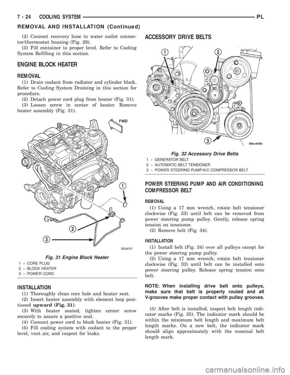
(2) Detach power cord plug from heater (Fig. 31).
(3) Loosen screw in center of heater. Remove
heater assembly (Fig. 31).
INSTALLATION
(1) Thoroughly clean core hole and heater seat.
(2) Insert heater assembly with element loop posi-
tionedupward (Fig. 31).
(3) With heater seated, tighten center screw
securely to assure a positive seal.
(4) Connect power cord to block heater (Fig. 31).
(5) Fill cooling system with coolant to the proper
level, vent air, and inspect for leaks.
ACCESSORY DRIVE BELTS
POWER STEERING PUMP AND AIR CONDITIONING
COMPRESSOR BELT
REMOVAL
(1) Using a 17 mm wrench, rotate belt tensioner
clockwise (Fig. 33) until belt can be removed from
power steering pump pulley. Gently, release spring
tension on tensioner.
(2) Remove belt (Fig. 34).
INSTALLATION
(1) Install belt (Fig. 34) over all pulleys except for
the power steering pump pulley.
(2) Using a 17 mm wrench, rotate belt tensioner
clockwise (Fig. 33) until belt can be installed onto
power steering pulley. Release spring tension onto
belt.
NOTE: When installing drive belt onto pulleys,
make sure that belt is properly routed and all
V-grooves make proper contact with pulley grooves.
(3) After belt is installed, inspect belt length indi-
cator marks (Fig. 35). The indicator mark should be
within the minimum belt length and maximum belt
length marks. On a new belt, the indicator mark
should align approximately with the nominal belt
length mark.
Fig. 31 Engine Block Heater
1 ± CORE PLUG
2 ± BLOCK HEATER
3 ± POWER CORD
Fig. 32 Accessory Drive Belts
1 ± GENERATOR BELT
2 ± AUTOMATIC BELT TENSIONER
3 ± POWER STEERING PUMP/A/C COMPRESSOR BELT
7 - 24 COOLING SYSTEMPL
REMOVAL AND INSTALLATION (Continued)