2000 DODGE NEON boot
[x] Cancel search: bootPage 4 of 1285
MAINTENANCE SCHEDULES
TABLE OF CONTENTS
page page
DESCRIPTION AND OPERATION
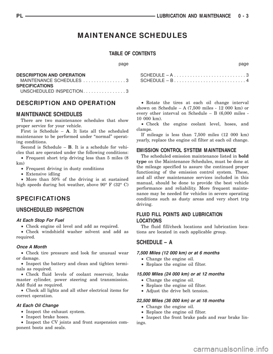
MAINTENANCE SCHEDULES................3
SPECIFICATIONS
UNSCHEDULED INSPECTION................3SCHEDULE ± A...........................3
SCHEDULE ± B...........................4
DESCRIPTION AND OPERATION
MAINTENANCE SCHEDULES
There are two maintenance schedules that show
proper service for your vehicle.
First is Schedule ±A. It lists all the scheduled
maintenance to be performed under ªnormalº operat-
ing conditions.
Second is Schedule ±B. It is a schedule for vehi-
cles that are operated under the following conditions:
²Frequent short trip driving less than 5 miles (8
km)
²Frequent driving in dusty conditions
²Extensive idling
²More than 50% of the driving is at sustained
high speeds during hot weather, above 90É F (32É C)
SPECIFICATIONS
UNSCHEDULED INSPECTION
At Each Stop For Fuel
²Check engine oil level and add as required.
²Check windshield washer solvent and add as
required.
Once A Month
²Check tire pressure and look for unusual wear
or damage.
²Inspect the battery and clean and tighten termi-
nals as required.
²Check fluid levels of coolant reservoir, brake
master cylinder, power steering and transmission.
Add fluid as required.
²Check all lights and all other electrical items for
correct operation.
At Each Oil Change
²Inspect the exhaust system.
²Inspect brake hoses.
²Inspect the CV joints and front suspension com-
ponent boots and seals.²Rotate the tires at each oil change interval
shown on Schedule ± A (7,500 miles - 12 000 km) or
every other interval on Schedule ± B (6,000 miles -
10 000 km).
²Check the engine coolant level, hoses, and
clamps.
If mileage is less than 7,500 miles (12 000 km)
yearly, replace the engine oil filter at each oil change.
EMISSION CONTROL SYSTEM MAINTENANCE
The scheduled emission maintenance listed inbold
typeon the Maintenance Schedules, must be done at
the mileage specified to assure the continued proper
functioning of the emission control system. These,
and all other maintenance services included in this
manual, should be done to provide the best vehicle
performance and reliability. More frequent mainte-
nance may be needed for vehicles in severe operating
conditions such as dusty areas and very short trip
driving.
FLUID FILL POINTS AND LUBRICATION
LOCATIONS
The fluid fill/check locations and lubrication loca-
tions are located in each applicable group.
SCHEDULE ± A
7,500 Miles (12 000 km) or at 6 months
²Change the engine oil.
²Replace the engine oil filter.
15,000 Miles (24 000 km) or at 12 months
²Change the engine oil.
²Replace the engine oil filter.
²Adjust the drive belt tension.
22,500 Miles (36 000 km) or at 18 months
²Change the engine oil.
²Replace the engine oil filter.
²Inspect the front brake pads and rear brake lin-
ings.
PLLUBRICATION AND MAINTENANCE 0 - 3
Page 5 of 1285

30,000 Miles (48 000 km) or at 24 months
²Change the engine oil.
²Replace the engine oil filter.
²Lubricate the front suspension lower ball joint.
²Inspect the tie rod ends and boot seals.
²Adjust the drive belt tension.
²Replace the engine air cleaner element (fil-
ter).
²Replace the engine spark plugs
²Change the automatic transaxle fluid.
37,500 Miles (60 000 km) or at 30 months
²Change the engine oil.
²Replace the engine oil filter.
45,000 Miles (72 000 km) or at 36 months
²Change the engine oil.
²Replace the engine oil filter.
²Inspect the front brake pads and rear brake lin-
ings.
²Adjust the drive belt tension.
²Flush and replace the engine coolant at 36
months, regardless of mileage.
52,500 Miles (84 000 km) or at 42 months
²Change the engine oil.
²Replace the engine oil filter.
²Flush and replace the engine coolant if not done
at 36 months.
60,000 Miles (96 000 km) or at 48 months
²Change the engine oil.
²Replace the engine oil filter.
²Check the PCV valve and replace, if neces-
sary. Not required if previously changed.*
²Lubricate the front suspension lower ball joints.
²Replace the drive belts.
²Replace the engine air cleaner element (fil-
ter).
²Replace the ignition cables.
²Replace the spark plugs.
²Change the automatic transaxle fluid.
67,500 Miles (108 000 km) or at 54 months
²Change the engine oil.
²Replace the engine oil filter.
²Inspect the front brake pads and rear brake lin-
ings.
75,000 Miles (120 000 km) or at 60 months
²Change the engine oil.
²Replace the engine oil filter.
²Adjust the drive belt tension.
²Flush and replace engine coolant if has been
30,000 miles (48 000 km) or 24 months since last
change.
82,500 Miles (132 000 km) or at 66 months
²Change the engine oil.
²Replace the engine oil filter.
²Flush and replace engine coolant if it has been
30,000 miles (48 000 km) or 24 months since last
change.
90,000 Miles (144 000 km) or at 72 months
²Change the engine oil.
²Replace the engine oil filter.
²Check the PCV valve and replace, if neces-
sary. Not required if previously changed.*
²Lubricate the front suspension lower ball joints.
²Inspect the front brake pads and rear brake lin-
ings.
²Adjust the drive belt tension.
²Replace the engine air cleaner element (fil-
ter).
²Replace the spark plugs.
²Inspect the serpentine drive belt, replace if nec-
essary. This maintenance is not required if the belt
was previously replaced.
²Change the automatic transaxle fluid.
97,500 Miles (156 000 km) or at 78 months
²Change the engine oil.
²Replace the engine oil filter.
105,000 Miles (168 000 km) or at 84 months
²Change the engine oil.
²Replace the engine oil filter.
²Replace the engine timing belt.
²Adjust the drive belt tension.
*This maintenance is recommended by Daimler-
Chrysler Corporation to the owner but is not
required to maintain the emissions warranty.
NOTE: Inspection and service should also be per-
formed anytime a malfunction is observed or sus-
pected. Retain all receipts.
SCHEDULE ± B
3,000 Miles (5 000 km)
²Change the engine oil.
6,000 Miles (10 000 km)
²Change the engine oil.
²Replace the engine oil filter.
9,000 Miles (14 000 km)
²Change the engine oil.
²Inspect the front brake pads and rear brake lin-
ings.
0 - 4 LUBRICATION AND MAINTENANCEPL
SPECIFICATIONS (Continued)
Page 18 of 1285
(4) Install a nut provided in adjustment package
on the replacement bolt. Tighten the nut until it's
snug, but still allowing the knuckle to slide in the
clevis bracket.
(5) Remove the original lower bolt.
(6) Install a bolt from the adjustment package into
the bottom hole of the strut clevis bracket. Install the
bolt from the rear.
(7) Install a nut provided in adjustment package
on the replacement bolt. Tighten the nut until it's
snug.
(8) Reinstall the tire and wheel assembly.
(9) Perform the above procedure to any of the
remaining struts as required.
(10) Lower the vehicle and jounce the front and
rear of the vehicle.
(11) Adjust the front or rear camber to the pre-
ferred setting by pushing or pulling on the top of the
tire. When camber is set to specifications, tighten the
upper and lower strut clevis bracket bolts. Again
jounce the front and rear of the vehicle, then verify
the camber settings.
(12) Torque front strut clevis bracket-to-steering
knuckle attaching bolts to 53 N´m (40 ft. lbs.), plus
an additional 1/4 turn after the torque is met. Torque
the rear strut clevis bracket-to-rear knuckle attach-
ing bolts to 95 N´m (70 ft. lbs.).
(13) Once camber is within specifications, adjust
toe to meet the preferred specification setting. Refer
to TOE within this wheel alignment service proce-
dure.
TOE
(1) Center the steering wheel and lock it in place
using a steering wheel clamp.
NOTE: When performing the toe setting procedure,
make sure the rear toe is set to the preferred spec-
ification before setting the front toe to the preferred
specification.
REAR TOE
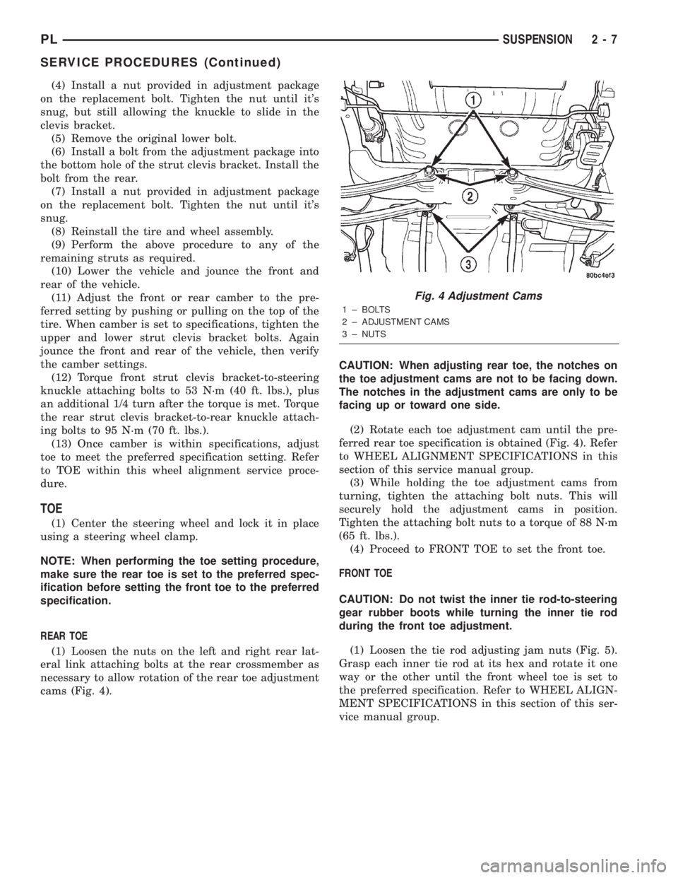
(1) Loosen the nuts on the left and right rear lat-
eral link attaching bolts at the rear crossmember as
necessary to allow rotation of the rear toe adjustment
cams (Fig. 4).CAUTION: When adjusting rear toe, the notches on
the toe adjustment cams are not to be facing down.
The notches in the adjustment cams are only to be
facing up or toward one side.
(2) Rotate each toe adjustment cam until the pre-
ferred rear toe specification is obtained (Fig. 4). Refer
to WHEEL ALIGNMENT SPECIFICATIONS in this
section of this service manual group.
(3) While holding the toe adjustment cams from
turning, tighten the attaching bolt nuts. This will
securely hold the adjustment cams in position.
Tighten the attaching bolt nuts to a torque of 88 N´m
(65 ft. lbs.).
(4) Proceed to FRONT TOE to set the front toe.
FRONT TOE
CAUTION: Do not twist the inner tie rod-to-steering
gear rubber boots while turning the inner tie rod
during the front toe adjustment.
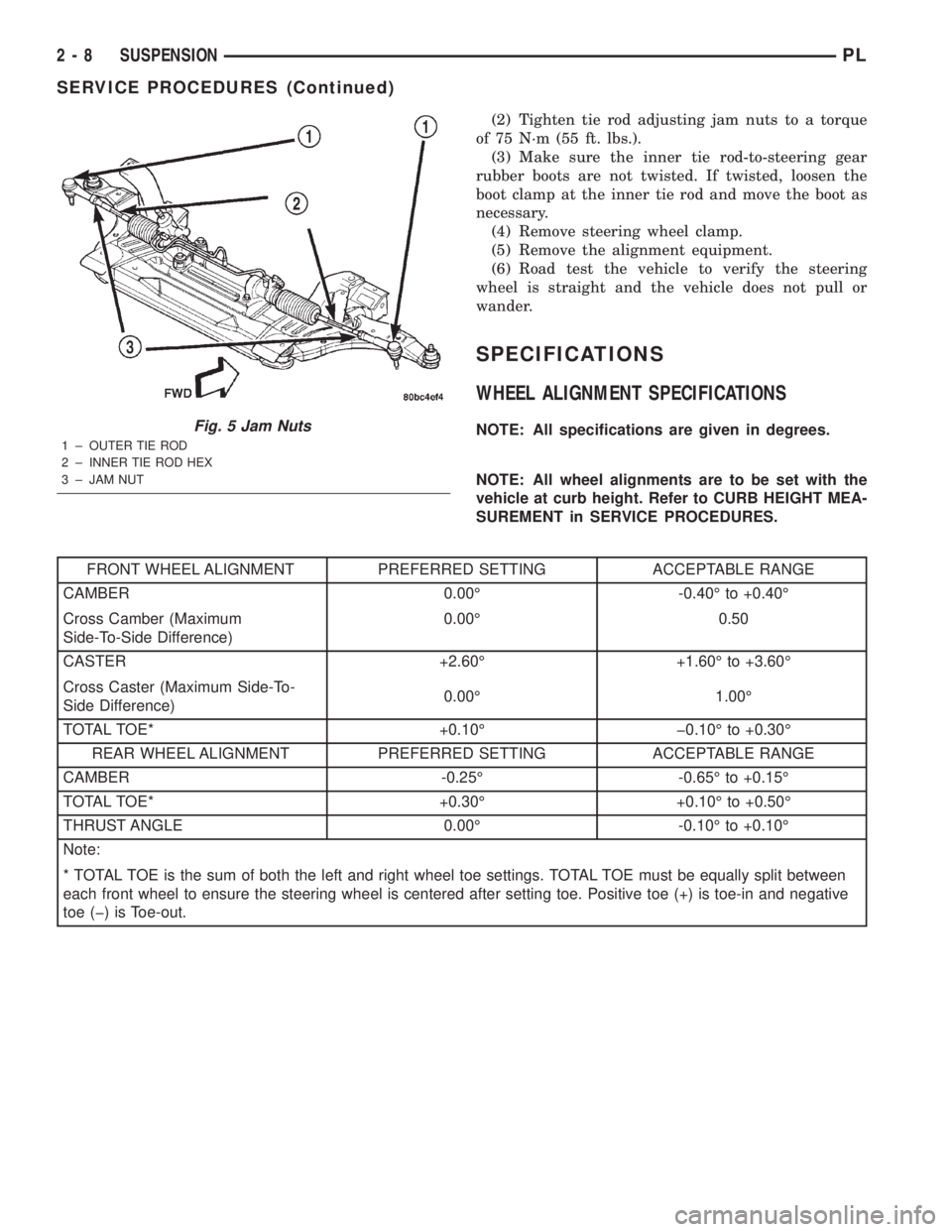
(1) Loosen the tie rod adjusting jam nuts (Fig. 5).
Grasp each inner tie rod at its hex and rotate it one
way or the other until the front wheel toe is set to
the preferred specification. Refer to WHEEL ALIGN-
MENT SPECIFICATIONS in this section of this ser-
vice manual group.
Fig. 4 Adjustment Cams
1 ± BOLTS
2 ± ADJUSTMENT CAMS
3 ± NUTS
PLSUSPENSION 2 - 7
SERVICE PROCEDURES (Continued)
Page 19 of 1285
(2) Tighten tie rod adjusting jam nuts to a torque
of 75 N´m (55 ft. lbs.).
(3) Make sure the inner tie rod-to-steering gear
rubber boots are not twisted. If twisted, loosen the
boot clamp at the inner tie rod and move the boot as
necessary.
(4) Remove steering wheel clamp.
(5) Remove the alignment equipment.
(6) Road test the vehicle to verify the steering
wheel is straight and the vehicle does not pull or
wander.
SPECIFICATIONS
WHEEL ALIGNMENT SPECIFICATIONS
NOTE: All specifications are given in degrees.
NOTE: All wheel alignments are to be set with the
vehicle at curb height. Refer to CURB HEIGHT MEA-
SUREMENT in SERVICE PROCEDURES.
FRONT WHEEL ALIGNMENT PREFERRED SETTING ACCEPTABLE RANGE
CAMBER 0.00É -0.40É to +0.40É
Cross Camber (Maximum
Side-To-Side Difference)0.00É 0.50
CASTER +2.60É +1.60É to +3.60É
Cross Caster (Maximum Side-To-
Side Difference)0.00É 1.00É
TOTAL TOE* +0.10É þ0.10É to +0.30É
REAR WHEEL ALIGNMENT PREFERRED SETTING ACCEPTABLE RANGE
CAMBER -0.25É -0.65É to +0.15É
TOTAL TOE* +0.30É +0.10É to +0.50É
THRUST ANGLE 0.00É -0.10É to +0.10É
Note:
* TOTAL TOE is the sum of both the left and right wheel toe settings. TOTAL TOE must be equally split between
each front wheel to ensure the steering wheel is centered after setting toe. Positive toe (+) is toe-in and negative
toe (þ) is Toe-out.
Fig. 5 Jam Nuts
1 ± OUTER TIE ROD
2 ± INNER TIE ROD HEX
3 ± JAM NUT
2 - 8 SUSPENSIONPL
SERVICE PROCEDURES (Continued)
Page 23 of 1285
BALL JOINT
The lower control arm connects to the steering
knuckle through a ball joint mounted at the outboard
end of the arm (Fig. 1). The ball joint is pressed into
the lower control arm and has a non-tapered stud
with a notch for steering knuckle pinch bolt clear-
ance. The ball joint stud is clamped and locked to the
steering knuckle lower leg using a pinch bolt.
The ball joint is lubricated for life during the man-
ufacturing process. Once lubricated for life, the
grease fitting head is snapped off by the manufac-
turer. This is done to eliminate the possibility of
lubrication later in the ball joints life thus damaging
the non-vented ball joint seal boot.
The ball joint used on this vehicle is replaceable
and, if found defective, can be serviced as a separate
component of the lower control arm.
STABILIZER BAR (FRONT)
The stabilizer bar helps control vehicle body roll.
Jounce and rebound movements affecting one wheel
are partially transmitted to the opposite wheel of the
vehicle to stabilize body roll.
The stabilizer bar interconnects both front lower
control arms of the vehicle and is attached to the
front suspension crossmember (Fig. 1).
Attachment of the stabilizer bar to the front sus-
pension crossmember is through 2 rubber-isolator
cushion and retainers (Fig. 1). The stabilizer bar
attachment to the lower control arm is done by uti-
lizing an isolated stabilizer bar link at each arm. All
components of the stabilizer bar are serviceable.
DIAGNOSIS AND TESTING
STRUT ASSEMBLY (FRONT)
Inspect the strut assembly for the following condi-
tions (Fig. 3):
²Inspect for a damaged or broken coil spring.
²Inspect for a torn or damaged strut assembly
dust shield.²Lift the dust shield and inspect the strut assem-
bly for evidence of fluid running from the upper end
of the strut fluid reservoir. (Actual leakage will be a
stream of fluid running down the side and dripping
off lower end of unit.) A slight amount of seepage
between the strut shaft and strut shaft seal is not
unusual and does not affect performance of the strut
assembly.
²Lift the dust shield and inspect the jounce
bumper for signs of damage or deterioration.
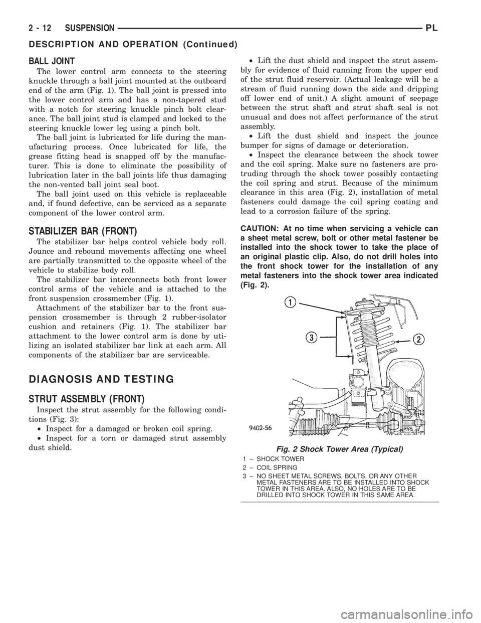
²Inspect the clearance between the shock tower
and the coil spring. Make sure no fasteners are pro-
truding through the shock tower possibly contacting
the coil spring and strut. Because of the minimum
clearance in this area (Fig. 2), installation of metal
fasteners could damage the coil spring coating and
lead to a corrosion failure of the spring.
CAUTION: At no time when servicing a vehicle can
a sheet metal screw, bolt or other metal fastener be
installed into the shock tower to take the place of
an original plastic clip. Also, do not drill holes into
the front shock tower for the installation of any
metal fasteners into the shock tower area indicated
(Fig. 2).
Fig. 2 Shock Tower Area (Typical)
1 ± SHOCK TOWER
2 ± COIL SPRING
3 ± NO SHEET METAL SCREWS, BOLTS, OR ANY OTHER
METAL FASTENERS ARE TO BE INSTALLED INTO SHOCK
TOWER IN THIS AREA. ALSO, NO HOLES ARE TO BE
DRILLED INTO SHOCK TOWER IN THIS SAME AREA.
2 - 12 SUSPENSIONPL
DESCRIPTION AND OPERATION (Continued)
Page 40 of 1285
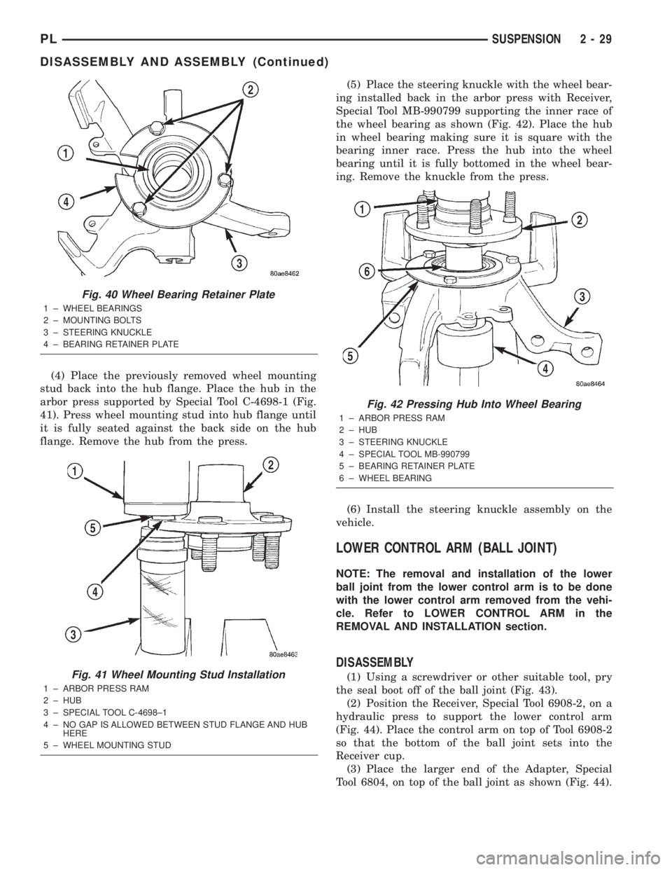
(4) Place the previously removed wheel mounting
stud back into the hub flange. Place the hub in the
arbor press supported by Special Tool C-4698-1 (Fig.
41). Press wheel mounting stud into hub flange until
it is fully seated against the back side on the hub
flange. Remove the hub from the press.(5) Place the steering knuckle with the wheel bear-
ing installed back in the arbor press with Receiver,
Special Tool MB-990799 supporting the inner race of
the wheel bearing as shown (Fig. 42). Place the hub
in wheel bearing making sure it is square with the
bearing inner race. Press the hub into the wheel
bearing until it is fully bottomed in the wheel bear-
ing. Remove the knuckle from the press.
(6) Install the steering knuckle assembly on the
vehicle.
LOWER CONTROL ARM (BALL JOINT)
NOTE: The removal and installation of the lower
ball joint from the lower control arm is to be done
with the lower control arm removed from the vehi-
cle. Refer to LOWER CONTROL ARM in the
REMOVAL AND INSTALLATION section.
DISASSEMBLY
(1) Using a screwdriver or other suitable tool, pry
the seal boot off of the ball joint (Fig. 43).
(2) Position the Receiver, Special Tool 6908-2, on a
hydraulic press to support the lower control arm
(Fig. 44). Place the control arm on top of Tool 6908-2
so that the bottom of the ball joint sets into the
Receiver cup.
(3) Place the larger end of the Adapter, Special
Tool 6804, on top of the ball joint as shown (Fig. 44).
Fig. 40 Wheel Bearing Retainer Plate
1 ± WHEEL BEARINGS
2 ± MOUNTING BOLTS
3 ± STEERING KNUCKLE
4 ± BEARING RETAINER PLATE
Fig. 41 Wheel Mounting Stud Installation
1 ± ARBOR PRESS RAM
2 ± HUB
3 ± SPECIAL TOOL C-4698±1
4 ± NO GAP IS ALLOWED BETWEEN STUD FLANGE AND HUB
HERE
5 ± WHEEL MOUNTING STUD
Fig. 42 Pressing Hub Into Wheel Bearing
1 ± ARBOR PRESS RAM
2 ± HUB
3 ± STEERING KNUCKLE
4 ± SPECIAL TOOL MB-990799
5 ± BEARING RETAINER PLATE
6 ± WHEEL BEARING
PLSUSPENSION 2 - 29
DISASSEMBLY AND ASSEMBLY (Continued)
Page 41 of 1285
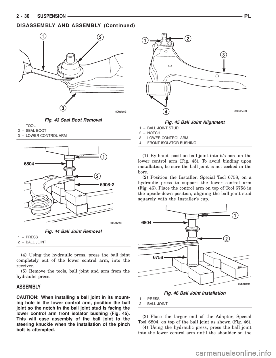
(4) Using the hydraulic press, press the ball joint
completely out of the lower control arm, into the
receiver.
(5) Remove the tools, ball joint and arm from the
hydraulic press.
ASSEMBLY
CAUTION: When installing a ball joint in its mount-
ing hole in the lower control arm, position the ball
joint so the notch in the ball joint stud is facing the
lower control arm front isolator bushing (Fig. 45).
This will ease assembly of the ball joint to the
steering knuckle when the installation of the pinch
bolt is attempted.(1) By hand, position ball joint into it's bore on the
lower control arm (Fig. 45). To avoid binding upon
installation, be sure the ball joint is not cocked in the
bore.
(2) Position the Installer, Special Tool 6758, on a
hydraulic press to support the lower control arm
(Fig. 46). Place the control arm on top of Tool 6758 in
the upside-down position, aligning the ball joint stud
squarely with the Installer's cup.
(3) Place the larger end of the Adapter, Special
Tool 6804, on top of the ball joint as shown (Fig. 46).
(4) Using the hydraulic press, press the ball joint
into the lower control arm until the shoulder on the
Fig. 43 Seal Boot Removal
1±TOOL
2 ± SEAL BOOT
3 ± LOWER CONTROL ARM
Fig. 44 Ball Joint Removal
1 ± PRESS
2 ± BALL JOINT
Fig. 45 Ball Joint Alignment
1 ± BALL JOINT STUD
2 ± NOTCH
3 ± LOWER CONTROL ARM
4 ± FRONT ISOLATOR BUSHING
Fig. 46 Ball Joint Installation
1 ± PRESS
2 ± BALL JOINT
2 - 30 SUSPENSIONPL
DISASSEMBLY AND ASSEMBLY (Continued)
Page 42 of 1285
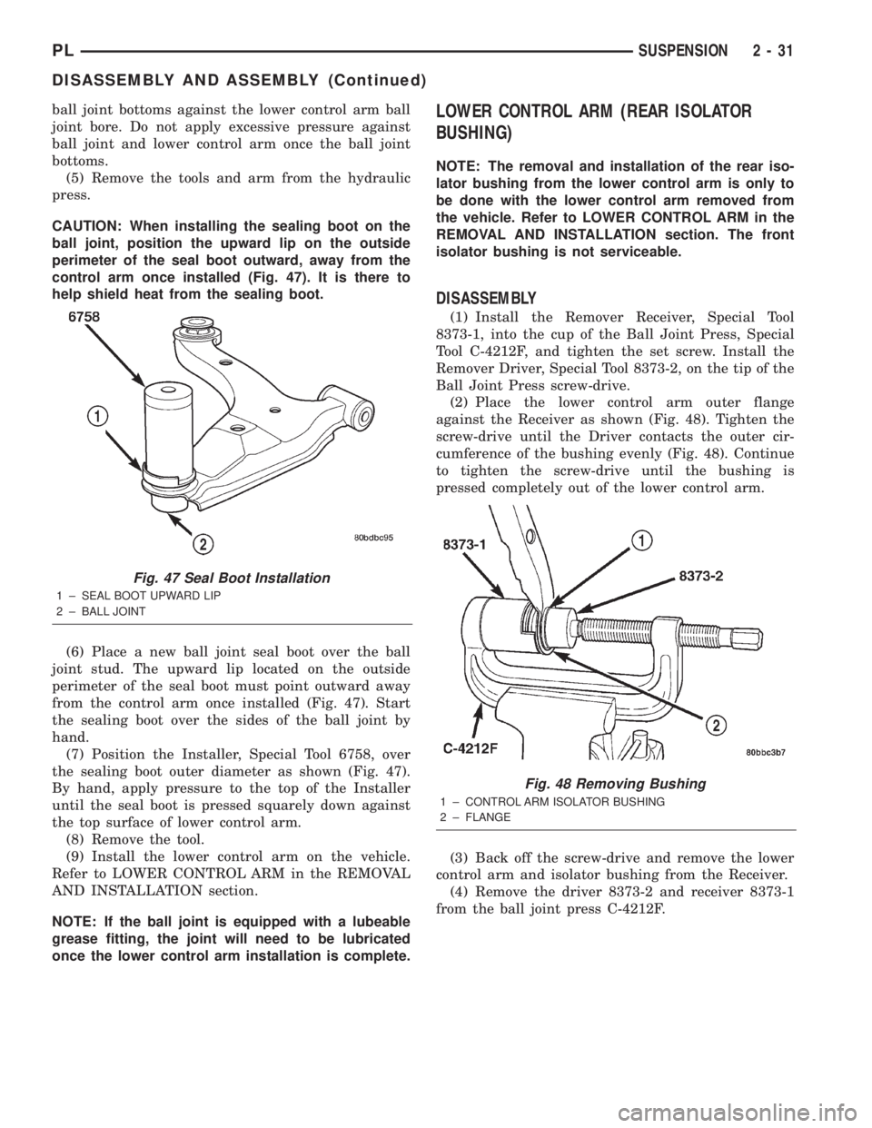
ball joint bottoms against the lower control arm ball
joint bore. Do not apply excessive pressure against
ball joint and lower control arm once the ball joint
bottoms.
(5) Remove the tools and arm from the hydraulic
press.
CAUTION: When installing the sealing boot on the
ball joint, position the upward lip on the outside
perimeter of the seal boot outward, away from the
control arm once installed (Fig. 47). It is there to
help shield heat from the sealing boot.
(6) Place a new ball joint seal boot over the ball
joint stud. The upward lip located on the outside
perimeter of the seal boot must point outward away
from the control arm once installed (Fig. 47). Start
the sealing boot over the sides of the ball joint by
hand.
(7) Position the Installer, Special Tool 6758, over
the sealing boot outer diameter as shown (Fig. 47).
By hand, apply pressure to the top of the Installer
until the seal boot is pressed squarely down against
the top surface of lower control arm.
(8) Remove the tool.
(9) Install the lower control arm on the vehicle.
Refer to LOWER CONTROL ARM in the REMOVAL
AND INSTALLATION section.
NOTE: If the ball joint is equipped with a lubeable
grease fitting, the joint will need to be lubricated
once the lower control arm installation is complete.LOWER CONTROL ARM (REAR ISOLATOR
BUSHING)
NOTE: The removal and installation of the rear iso-
lator bushing from the lower control arm is only to
be done with the lower control arm removed from
the vehicle. Refer to LOWER CONTROL ARM in the
REMOVAL AND INSTALLATION section. The front
isolator bushing is not serviceable.
DISASSEMBLY
(1) Install the Remover Receiver, Special Tool
8373-1, into the cup of the Ball Joint Press, Special
Tool C-4212F, and tighten the set screw. Install the
Remover Driver, Special Tool 8373-2, on the tip of the
Ball Joint Press screw-drive.
(2) Place the lower control arm outer flange
against the Receiver as shown (Fig. 48). Tighten the
screw-drive until the Driver contacts the outer cir-
cumference of the bushing evenly (Fig. 48). Continue
to tighten the screw-drive until the bushing is
pressed completely out of the lower control arm.
(3) Back off the screw-drive and remove the lower
control arm and isolator bushing from the Receiver.
(4) Remove the driver 8373-2 and receiver 8373-1
from the ball joint press C-4212F.
Fig. 47 Seal Boot Installation
1 ± SEAL BOOT UPWARD LIP
2 ± BALL JOINT
Fig. 48 Removing Bushing
1 ± CONTROL ARM ISOLATOR BUSHING
2 ± FLANGE
PLSUSPENSION 2 - 31
DISASSEMBLY AND ASSEMBLY (Continued)