2000 DODGE NEON boot
[x] Cancel search: bootPage 241 of 1285
IGNITION INTERLOCK
OPERATION
All vehicles equipped with automatic transaxles
have an interlock system. The system prevents shift-
ing the vehicle out of Park unless the ignition lock
cylinder is in the Off, Run or Start position. In addi-
tion, the operator cannot rotate the key to the lock
position unless the shifter is in the park position. On
vehicles equipped with floor shift refer to the - Tran-
saxle for Automatic Transmission Shifter/Ignition
Interlock.
REMOVAL AND INSTALLATION
SPARK PLUG SERVICE
Failure to route the cables properly could cause the
radio to reproduce ignition noise, cross ignition of the
spark plugs or short circuit the cables to ground.
REMOVAL
REMOVE CABLES FROM COIL FIRST.
Always remove the spark plug cable by grasping
the top of the spark plug insulator, turning the boot
1/2 turn and pulling straight up in a steady motion.
(1) Remove the spark plug using a quality socket
with a rubber or foam insert.
(2) Inspect the spark plug condition.
INSTALLATION
(1) To avoid cross threading, start the spark plug
into the cylinder head by hand.
(2) Tighten spark plugs to 28 N´m (20 ft. lbs.)
torque.
(3) Install spark plug insulators over spark plugs.
Ensure the top of the spark plug insulator covers the
upper end of the spark plug tube.
Reconnect to coil.
SPARK PLUG CABLE SERVICE
Failure to route the cables properly could cause the
radio to reproduce ignition noise, cross ignition of the
spark plugs or short circuit the cables to ground.
REMOVAL
Remove spark plug cable from coil first.
Always remove the spark plug cable by grasping
the top of the spark plug insulator, turning the boot
1/2 turn and pulling straight up in a steady motion.
INSTALLATION
Install spark plug insulators over spark plugs.
Ensure the top of the spark plug insulator covers the
upper end of the spark plug tube. The connect theother end to coil pack. Be sure that dual plastic clip
holds the cables off of the valve cover.
IGNITION COIL
The electronic ignition coil pack attaches directly
to the valve cover (Fig. 11).
REMOVAL
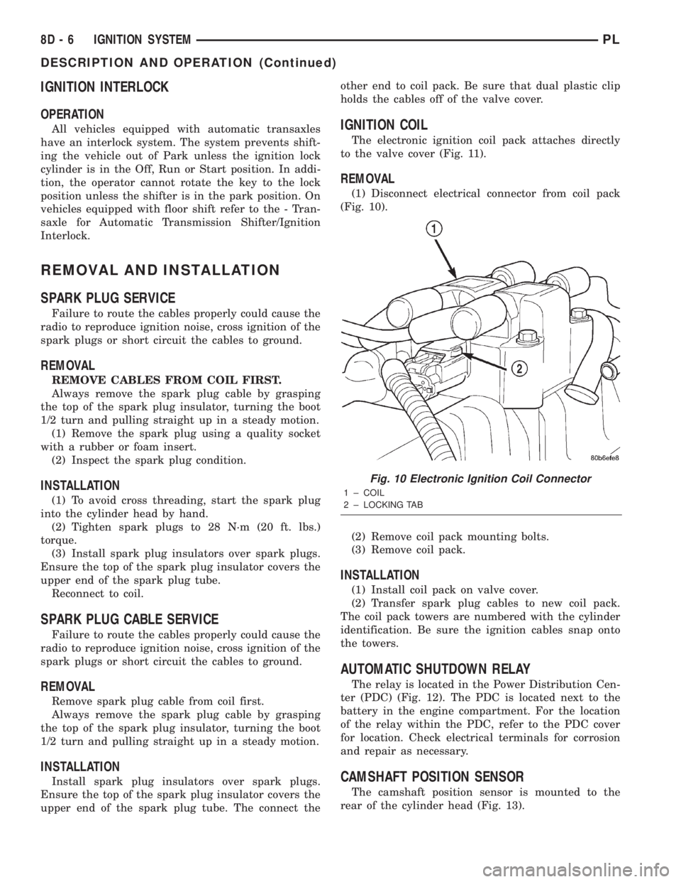
(1) Disconnect electrical connector from coil pack
(Fig. 10).
(2) Remove coil pack mounting bolts.
(3) Remove coil pack.
INSTALLATION
(1) Install coil pack on valve cover.
(2) Transfer spark plug cables to new coil pack.
The coil pack towers are numbered with the cylinder
identification. Be sure the ignition cables snap onto
the towers.
AUTOMATIC SHUTDOWN RELAY
The relay is located in the Power Distribution Cen-
ter (PDC) (Fig. 12). The PDC is located next to the
battery in the engine compartment. For the location
of the relay within the PDC, refer to the PDC cover
for location. Check electrical terminals for corrosion
and repair as necessary.
CAMSHAFT POSITION SENSOR
The camshaft position sensor is mounted to the
rear of the cylinder head (Fig. 13).
Fig. 10 Electronic Ignition Coil Connector
1 ± COIL
2 ± LOCKING TAB
8D - 6 IGNITION SYSTEMPL
DESCRIPTION AND OPERATION (Continued)
Page 264 of 1285
(15) Rotate the A/C outlet registers to the full
down position. Grip each outlet at its outboard end
and gently over-rotate to release from its pivot point.
Swing outlet straight out and remove by hand
(16) Remove the (4) HVAC control knobs by pull-
ing them straight off the switch shaft by hand.
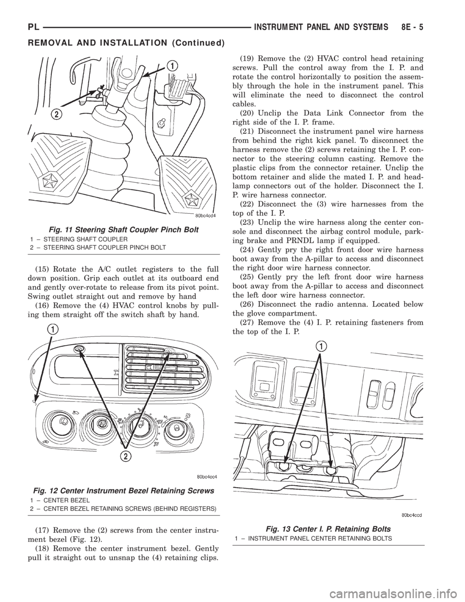
(17) Remove the (2) screws from the center instru-
ment bezel (Fig. 12).
(18) Remove the center instrument bezel. Gently
pull it straight out to unsnap the (4) retaining clips.(19) Remove the (2) HVAC control head retaining
screws. Pull the control away from the I. P. and
rotate the control horizontally to position the assem-
bly through the hole in the instrument panel. This
will eliminate the need to disconnect the control
cables.
(20) Unclip the Data Link Connector from the
right side of the I. P. frame.
(21) Disconnect the instrument panel wire harness
from behind the right kick panel. To disconnect the
harness remove the (2) screws retaining the I. P. con-
nector to the steering column casting. Remove the
plastic clips from the connector retainer. Unclip the
bottom retainer and slide the mated I. P. and head-
lamp connectors out of the holder. Disconnect the I.
P. wire harness connector.
(22) Disconnect the (3) wire harnesses from the
top of the I. P.
(23) Unclip the wire harness along the center con-
sole and disconnect the airbag control module, park-
ing brake and PRNDL lamp if equipped.
(24) Gently pry the right front door wire harness
boot away from the A-pillar to access and disconnect
the right door wire harness connector.
(25) Gently pry the left front door wire harness
boot away from the A-pillar to access and disconnect
the left door wire harness connector.
(26) Disconnect the radio antenna. Located below
the glove compartment.
(27) Remove the (4) I. P. retaining fasteners from
the top of the I. P.
Fig. 11 Steering Shaft Coupler Pinch Bolt
1 ± STEERING SHAFT COUPLER
2 ± STEERING SHAFT COUPLER PINCH BOLT
Fig. 12 Center Instrument Bezel Retaining Screws
1 ± CENTER BEZEL
2±
CENTER BEZEL RETAINING SCREWS (BEHIND REGISTERS)
Fig. 13 Center I. P. Retaining Bolts
1 ± INSTRUMENT PANEL CENTER RETAINING BOLTS
PLINSTRUMENT PANEL AND SYSTEMS 8E - 5
REMOVAL AND INSTALLATION (Continued)
Page 265 of 1285
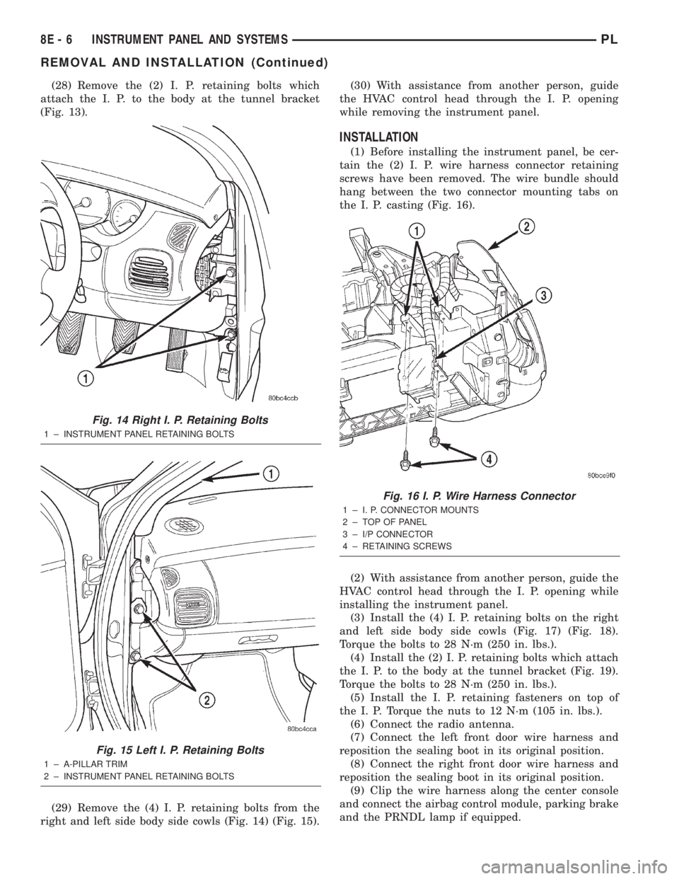
(28) Remove the (2) I. P. retaining bolts which
attach the I. P. to the body at the tunnel bracket
(Fig. 13).
(29) Remove the (4) I. P. retaining bolts from the
right and left side body side cowls (Fig. 14) (Fig. 15).(30) With assistance from another person, guide
the HVAC control head through the I. P. opening
while removing the instrument panel.
INSTALLATION
(1) Before installing the instrument panel, be cer-
tain the (2) I. P. wire harness connector retaining
screws have been removed. The wire bundle should
hang between the two connector mounting tabs on
the I. P. casting (Fig. 16).
(2) With assistance from another person, guide the
HVAC control head through the I. P. opening while
installing the instrument panel.
(3) Install the (4) I. P. retaining bolts on the right
and left side body side cowls (Fig. 17) (Fig. 18).
Torque the bolts to 28 N´m (250 in. lbs.).
(4) Install the (2) I. P. retaining bolts which attach
the I. P. to the body at the tunnel bracket (Fig. 19).
Torque the bolts to 28 N´m (250 in. lbs.).
(5) Install the I. P. retaining fasteners on top of
the I. P. Torque the nuts to 12 N´m (105 in. lbs.).
(6) Connect the radio antenna.
(7) Connect the left front door wire harness and
reposition the sealing boot in its original position.
(8) Connect the right front door wire harness and
reposition the sealing boot in its original position.
(9) Clip the wire harness along the center console
and connect the airbag control module, parking brake
and the PRNDL lamp if equipped.
Fig. 14 Right I. P. Retaining Bolts
1 ± INSTRUMENT PANEL RETAINING BOLTS
Fig. 15 Left I. P. Retaining Bolts
1 ± A-PILLAR TRIM
2 ± INSTRUMENT PANEL RETAINING BOLTS
Fig. 16 I. P. Wire Harness Connector
1 ± I. P. CONNECTOR MOUNTS
2 ± TOP OF PANEL
3 ± I/P CONNECTOR
4 ± RETAINING SCREWS
8E - 6 INSTRUMENT PANEL AND SYSTEMSPL
REMOVAL AND INSTALLATION (Continued)
Page 330 of 1285
(2) Rotate the turn signal lamp socket one-quarter
turn and pull straight from the headlamp assembly.
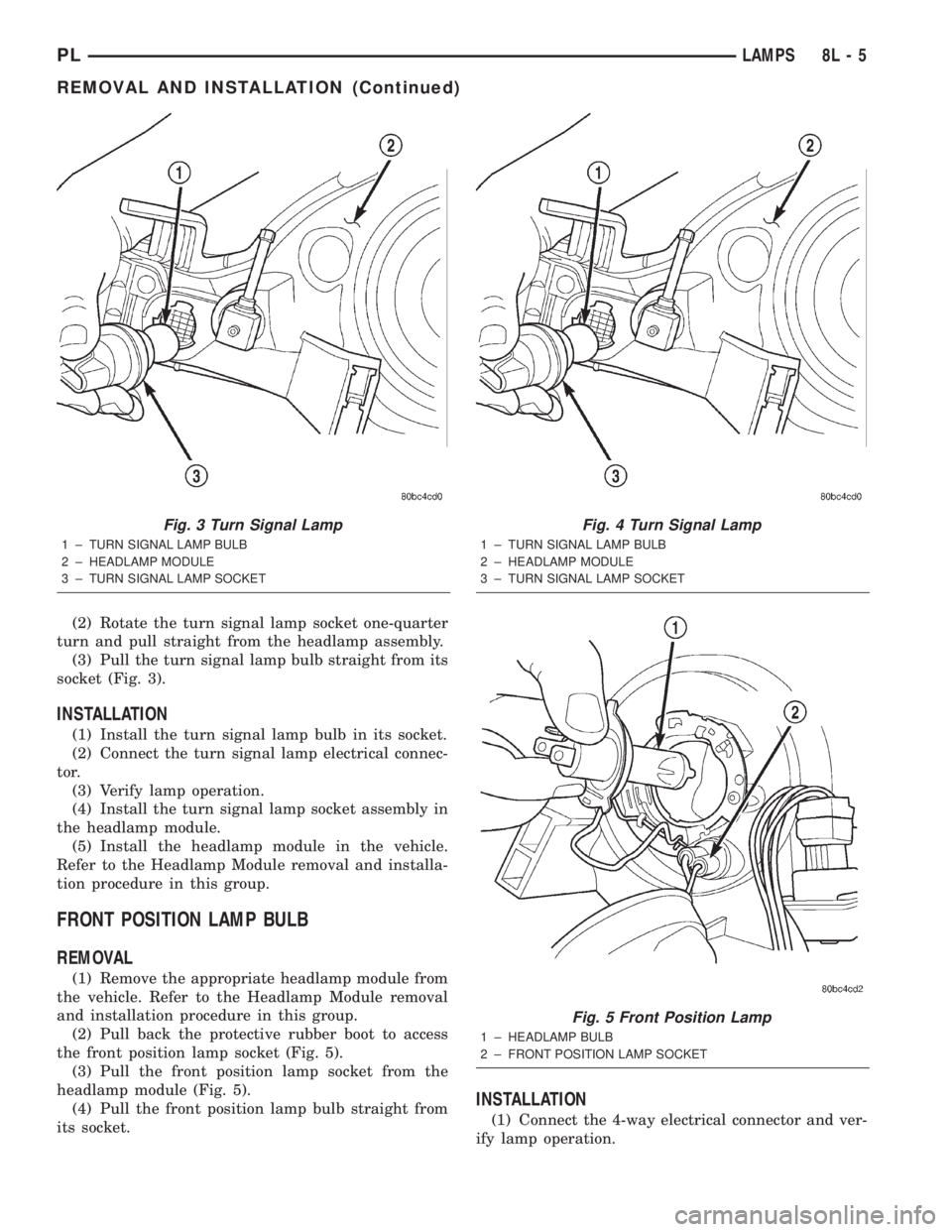
(3) Pull the turn signal lamp bulb straight from its
socket (Fig. 3).
INSTALLATION
(1) Install the turn signal lamp bulb in its socket.
(2) Connect the turn signal lamp electrical connec-
tor.
(3) Verify lamp operation.
(4) Install the turn signal lamp socket assembly in
the headlamp module.
(5) Install the headlamp module in the vehicle.
Refer to the Headlamp Module removal and installa-
tion procedure in this group.
FRONT POSITION LAMP BULB
REMOVAL
(1) Remove the appropriate headlamp module from
the vehicle. Refer to the Headlamp Module removal
and installation procedure in this group.
(2) Pull back the protective rubber boot to access
the front position lamp socket (Fig. 5).
(3) Pull the front position lamp socket from the
headlamp module (Fig. 5).
(4) Pull the front position lamp bulb straight from
its socket.
INSTALLATION
(1) Connect the 4-way electrical connector and ver-
ify lamp operation.
Fig. 3 Turn Signal Lamp
1 ± TURN SIGNAL LAMP BULB
2 ± HEADLAMP MODULE
3 ± TURN SIGNAL LAMP SOCKET
Fig. 4 Turn Signal Lamp
1 ± TURN SIGNAL LAMP BULB
2 ± HEADLAMP MODULE
3 ± TURN SIGNAL LAMP SOCKET
Fig. 5 Front Position Lamp
1 ± HEADLAMP BULB
2 ± FRONT POSITION LAMP SOCKET
PLLAMPS 8L - 5
REMOVAL AND INSTALLATION (Continued)
Page 331 of 1285
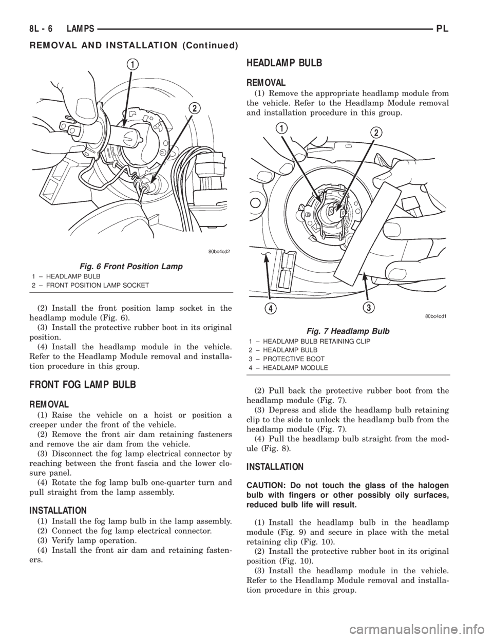
(2) Install the front position lamp socket in the
headlamp module (Fig. 6).
(3) Install the protective rubber boot in its original
position.
(4) Install the headlamp module in the vehicle.
Refer to the Headlamp Module removal and installa-
tion procedure in this group.
FRONT FOG LAMP BULB
REMOVAL
(1) Raise the vehicle on a hoist or position a
creeper under the front of the vehicle.
(2) Remove the front air dam retaining fasteners
and remove the air dam from the vehicle.
(3) Disconnect the fog lamp electrical connector by
reaching between the front fascia and the lower clo-
sure panel.
(4) Rotate the fog lamp bulb one-quarter turn and
pull straight from the lamp assembly.
INSTALLATION
(1) Install the fog lamp bulb in the lamp assembly.
(2) Connect the fog lamp electrical connector.
(3) Verify lamp operation.
(4) Install the front air dam and retaining fasten-
ers.
HEADLAMP BULB
REMOVAL
(1) Remove the appropriate headlamp module from
the vehicle. Refer to the Headlamp Module removal
and installation procedure in this group.
(2) Pull back the protective rubber boot from the
headlamp module (Fig. 7).
(3) Depress and slide the headlamp bulb retaining
clip to the side to unlock the headlamp bulb from the
headlamp module (Fig. 7).
(4) Pull the headlamp bulb straight from the mod-
ule (Fig. 8).
INSTALLATION
CAUTION: Do not touch the glass of the halogen
bulb with fingers or other possibly oily surfaces,
reduced bulb life will result.
(1) Install the headlamp bulb in the headlamp
module (Fig. 9) and secure in place with the metal
retaining clip (Fig. 10).
(2) Install the protective rubber boot in its original
position (Fig. 10).
(3) Install the headlamp module in the vehicle.
Refer to the Headlamp Module removal and installa-
tion procedure in this group.
Fig. 6 Front Position Lamp
1 ± HEADLAMP BULB
2 ± FRONT POSITION LAMP SOCKET
Fig. 7 Headlamp Bulb
1 ± HEADLAMP BULB RETAINING CLIP
2 ± HEADLAMP BULB
3 ± PROTECTIVE BOOT
4 ± HEADLAMP MODULE
8L - 6 LAMPSPL
REMOVAL AND INSTALLATION (Continued)
Page 332 of 1285
REAR LICENSE PLATE LAMP BULBS
REMOVAL
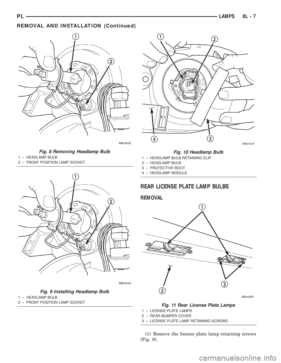
(1) Remove the license plate lamp retaining screws
(Fig. 8).
Fig. 8 Removing Headlamp Bulb
1 ± HEADLAMP BULB
2 ± FRONT POSITION LAMP SOCKET
Fig. 9 Installing Headlamp Bulb
1 ± HEADLAMP BULB
2 ± FRONT POSITION LAMP SOCKET
Fig. 10 Headlamp Bulb
1 ± HEADLAMP BULB RETAINING CLIP
2 ± HEADLAMP BULB
3 ± PROTECTIVE BOOT
4 ± HEADLAMP MODULE
Fig. 11 Rear License Plate Lamps
1 ± LICENSE PLATE LAMPS
2 ± REAR BUMPER COVER
3 ± LICENSE PLATE LAMP RETAINING SCREWS
PLLAMPS 8L - 7
REMOVAL AND INSTALLATION (Continued)
Page 914 of 1285
TRANSAXLE
TABLE OF CONTENTS
page page
NV T350 (A-578) MANUAL TRANSAXLE........ 131TH AUTOMATIC TRANSAXLE.............. 54
NV T350 (A-578) MANUAL TRANSAXLE
TABLE OF CONTENTS
page page
GENERAL INFORMATION
NV T350 (A578) MANUAL TRANSAXLE.........1
TRANSAXLE IDENTIFICATION................2
FLUID REQUIREMENTS....................2
SPECIAL ADDITIVES.......................2
SEALANTS..............................2
GEAR RATIOS............................2
GEARSHIFT PATTERN......................3
DIAGNOSIS AND TESTING
COMMON PROBLEM CAUSES...............3
HARD SHIFTING..........................3
NOISY OPERATION........................3
SLIPS OUT OF GEAR......................3
LOW LUBRICANT LEVEL....................4
FLUID LEAKS............................4
CLUTCH PROBLEMS.......................4
SERVICE PROCEDURES
FLUID DRAIN AND FILL.....................4
REMOVAL AND INSTALLATION
GEARSHIFT KNOB........................4
GEARSHIFT BOOT........................5
GEARSHIFT CABLE ASSEMBLY..............6
GEARSHIFT MECHANISM REPLACEMENT......9
VEHICLE SPEED SENSOR AND DRIVE
PINION...............................11
BACK-UP LAMP SWITCH...................12CROSSOVER LEVER......................12
SELECTOR LEVER.......................12
AXLE SHAFT SEALS......................13
SHIFT SHAFT SEALS......................13
TRANSAXLE............................14
DISASSEMBLY AND ASSEMBLY
TRANSAXLE............................18
INPUT SHAFT...........................31
OUTPUT SHAFT.........................36
DIFFERENTIAL..........................36
SYNCHRONIZER.........................41
SHIFT RAILS OVERHAUL..................42
TRANSAXLE CASE OVERHAUL..............42
CLEANING AND INSPECTION
TRANSAXLE............................48
SYNCHRONIZER.........................48
ADJUSTMENTS
GEARSHIFT CROSSOVER CABLE...........49
BEARING ADJUSTMENT PROCEDURE........50
DIFFERENTIAL BEARING PRELOAD
ADJUSTMENT..........................50
SPECIFICATIONS
NV T350 (A-578) SPECIFICATIONS...........51
SPECIAL TOOLS
NV T350 (A-578) MANUAL TRANSAXLE........52
GENERAL INFORMATION
NV T350 (A578) MANUAL TRANSAXLE
The NV T350 (A-578) transaxle is a fully synchro-
nized (except reverse), constant-mesh transaxle. The
transaxle case is constructed of die-cast aluminum,
and is a two-piece design (bell housing case half and
rear housing case half) with a steel end plate bearing
cover. All forward gears are in constant-mesh witheach other, which eliminates the need to move gears
together for engagement. This feature improves
response and eliminates gear ªclashº noises. The
reverse idler gear is supported and rotates on a spin-
dle idler shaft. Depending on application, a reverse
gear brake/blocking ring is available on some units
for shifting ease.
The NV T350 (A-578) transaxle also incorporates an
open differential, which converts power from the output
shaft pinion gear to the differential ring gear. The dif-
PLTRANSAXLE 21 - 1
Page 917 of 1285
LOW LUBRICANT LEVEL
Insufficient transaxle lubricant is usually the
result of leaks, or inaccurate fluid level check or refill
method. Leakage is evident by the presence of oil
around the leak point. If leakage is not evident, the
condition is probably the result of an underfill.
If air±powered lubrication equipment is used to fill
a transaxle, be sure the equipment is properly cali-
brated. Equipment out of calibration can lead to an
underfill condition.
FLUID LEAKS
Fluid leaks can occur around the input shaft seal,
axleshaft seals, case split lines, and the end cover. Be
careful not to misdiagnose an input shaft seal leak
for an engine rear main seal leak. Also, the transaxle
case sealer (split line) will accumulate dirt and look
like an oil leak.
CLUTCH PROBLEMS
Worn, damaged, or misaligned clutch components
can cause difficult shifting, gear clash, and noise.
A worn or damaged clutch disc, pressure plate, or
release bearing can cause hard shifting and gear
clash.
SERVICE PROCEDURES
FLUID DRAIN AND FILL
All NV T350 (A-578) transaxles are equipped with
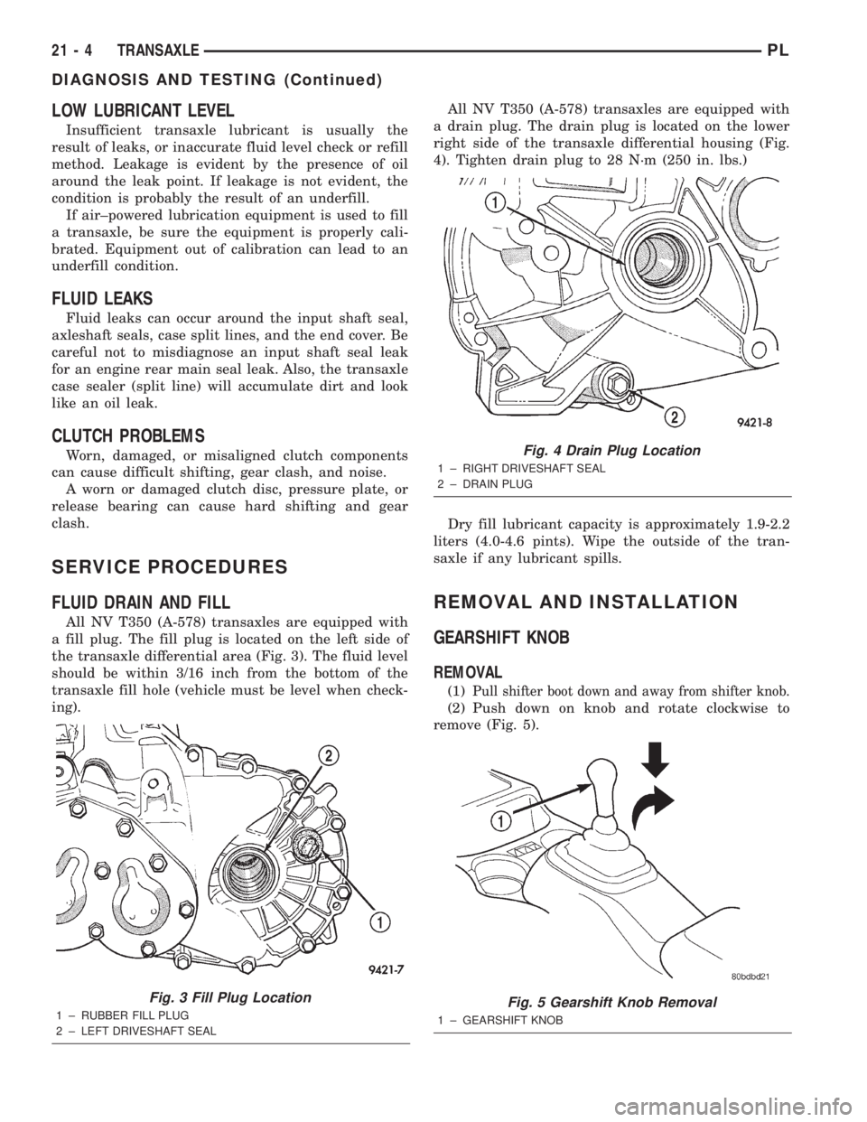
a fill plug. The fill plug is located on the left side of
the transaxle differential area (Fig. 3). The fluid level
should be within 3/16 inch from the bottom of the
transaxle fill hole (vehicle must be level when check-
ing).All NV T350 (A-578) transaxles are equipped with
a drain plug. The drain plug is located on the lower
right side of the transaxle differential housing (Fig.
4). Tighten drain plug to 28 N´m (250 in. lbs.)
Dry fill lubricant capacity is approximately 1.9-2.2
liters (4.0-4.6 pints). Wipe the outside of the tran-
saxle if any lubricant spills.
REMOVAL AND INSTALLATION
GEARSHIFT KNOB
REMOVAL
(1)Pull shifter boot down and away from shifter knob.
(2) Push down on knob and rotate clockwise to
remove (Fig. 5).
Fig. 3 Fill Plug Location
1 ± RUBBER FILL PLUG
2 ± LEFT DRIVESHAFT SEAL
Fig. 4 Drain Plug Location
1 ± RIGHT DRIVESHAFT SEAL
2 ± DRAIN PLUG
Fig. 5 Gearshift Knob Removal
1 ± GEARSHIFT KNOB
21 - 4 TRANSAXLEPL
DIAGNOSIS AND TESTING (Continued)