2000 DODGE NEON boot
[x] Cancel search: bootPage 136 of 1285
CALIPER PISTON AND SEALS
CALIPER PISTON REMOVAL
WARNING: UNDER NO CONDITION SHOULD HIGH
PRESSURE AIR EVER BE USED TO REMOVE A PIS-
TON FROM A CALIPER BORE. PERSONAL INJURY
COULD RESULT FROM SUCH A PRACTICE.
NOTE: The safest way to remove the piston from
the caliper bore is to use the hydraulic pressure of
the vehicle's brake system.
(1) Following the removal procedure in DISC
BRAKE SHOES found in this section, remove the
caliper from the brake rotor and hang the assembly
on a wire hook away from rotor and body of the vehi-
cle so brake fluid cannot get on these components.
Remove the brake shoes, and place a small piece of
wood between the piston and caliper fingers.
(2) Carefully depress the brake pedal to hydrauli-
cally push piston out of its bore. Once completed,
apply and hold down the brake pedal to any position
beyond the first inch of pedal travel using a brake
pedal holding tool. This will prevent the fluid in the
master cylinder reservoir from completely draining
out.(3) Disconnect the brake fluid flex hose from the
caliper assembly and remove it from the vehicle.
CALIPER SEAL REMOVAL
CAUTION: Do not use excessive force when clamp-
ing caliper in vise. Excessive vise pressure will
cause bore distortion.
(1) To disassemble the caliper, mount it in a vise
equipped with protective jaws.
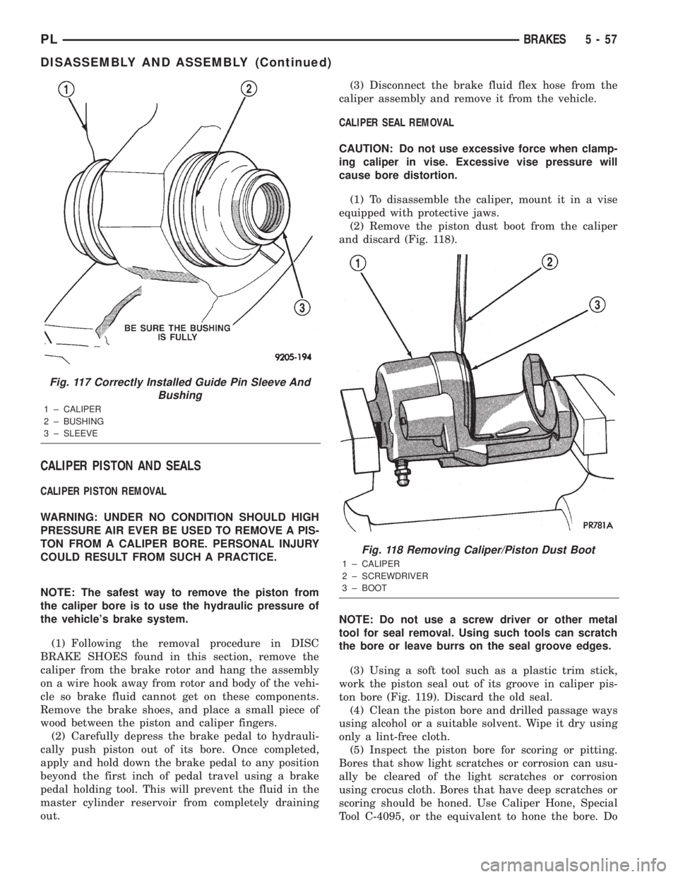
(2) Remove the piston dust boot from the caliper
and discard (Fig. 118).
NOTE: Do not use a screw driver or other metal
tool for seal removal. Using such tools can scratch
the bore or leave burrs on the seal groove edges.
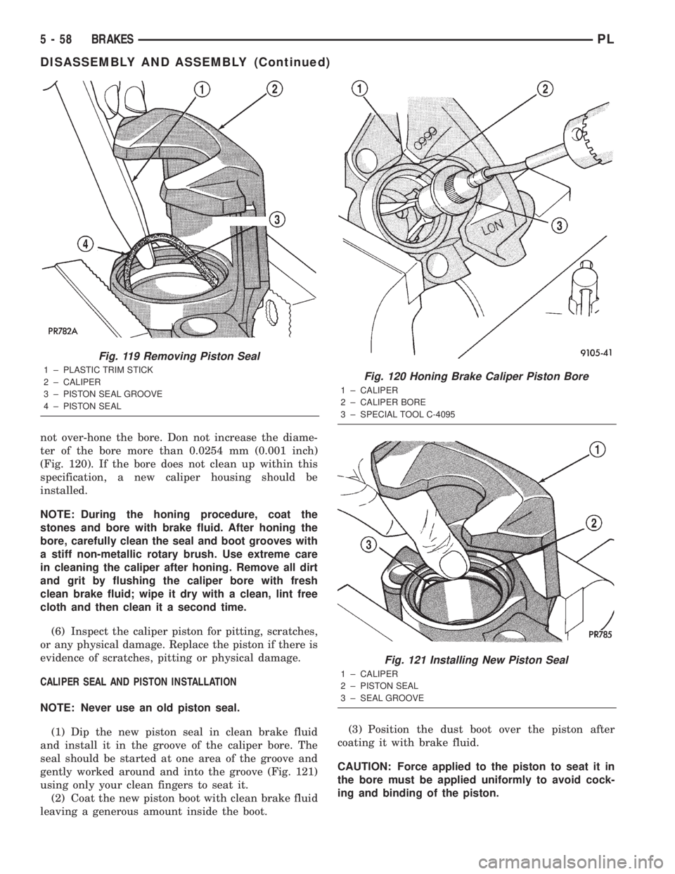
(3) Using a soft tool such as a plastic trim stick,
work the piston seal out of its groove in caliper pis-
ton bore (Fig. 119). Discard the old seal.
(4) Clean the piston bore and drilled passage ways
using alcohol or a suitable solvent. Wipe it dry using
only a lint-free cloth.
(5) Inspect the piston bore for scoring or pitting.
Bores that show light scratches or corrosion can usu-
ally be cleared of the light scratches or corrosion
using crocus cloth. Bores that have deep scratches or
scoring should be honed. Use Caliper Hone, Special
Tool C-4095, or the equivalent to hone the bore. Do
Fig. 117 Correctly Installed Guide Pin Sleeve And
Bushing
1 ± CALIPER
2 ± BUSHING
3 ± SLEEVE
Fig. 118 Removing Caliper/Piston Dust Boot
1 ± CALIPER
2 ± SCREWDRIVER
3 ± BOOT
PLBRAKES 5 - 57
DISASSEMBLY AND ASSEMBLY (Continued)
Page 137 of 1285
not over-hone the bore. Don not increase the diame-
ter of the bore more than 0.0254 mm (0.001 inch)
(Fig. 120). If the bore does not clean up within this
specification, a new caliper housing should be
installed.
NOTE: During the honing procedure, coat the
stones and bore with brake fluid. After honing the
bore, carefully clean the seal and boot grooves with
a stiff non-metallic rotary brush. Use extreme care
in cleaning the caliper after honing. Remove all dirt
and grit by flushing the caliper bore with fresh
clean brake fluid; wipe it dry with a clean, lint free
cloth and then clean it a second time.
(6) Inspect the caliper piston for pitting, scratches,
or any physical damage. Replace the piston if there is
evidence of scratches, pitting or physical damage.
CALIPER SEAL AND PISTON INSTALLATION
NOTE: Never use an old piston seal.
(1) Dip the new piston seal in clean brake fluid
and install it in the groove of the caliper bore. The
seal should be started at one area of the groove and
gently worked around and into the groove (Fig. 121)
using only your clean fingers to seat it.
(2) Coat the new piston boot with clean brake fluid
leaving a generous amount inside the boot.(3) Position the dust boot over the piston after
coating it with brake fluid.
CAUTION: Force applied to the piston to seat it in
the bore must be applied uniformly to avoid cock-
ing and binding of the piston.
Fig. 119 Removing Piston Seal
1 ± PLASTIC TRIM STICK
2 ± CALIPER
3 ± PISTON SEAL GROOVE
4 ± PISTON SEALFig. 120 Honing Brake Caliper Piston Bore
1 ± CALIPER
2 ± CALIPER BORE
3 ± SPECIAL TOOL C-4095
Fig. 121 Installing New Piston Seal
1 ± CALIPER
2 ± PISTON SEAL
3 ± SEAL GROOVE
5 - 58 BRAKESPL
DISASSEMBLY AND ASSEMBLY (Continued)
Page 138 of 1285
(4) Install piston into caliper bore pushing it past
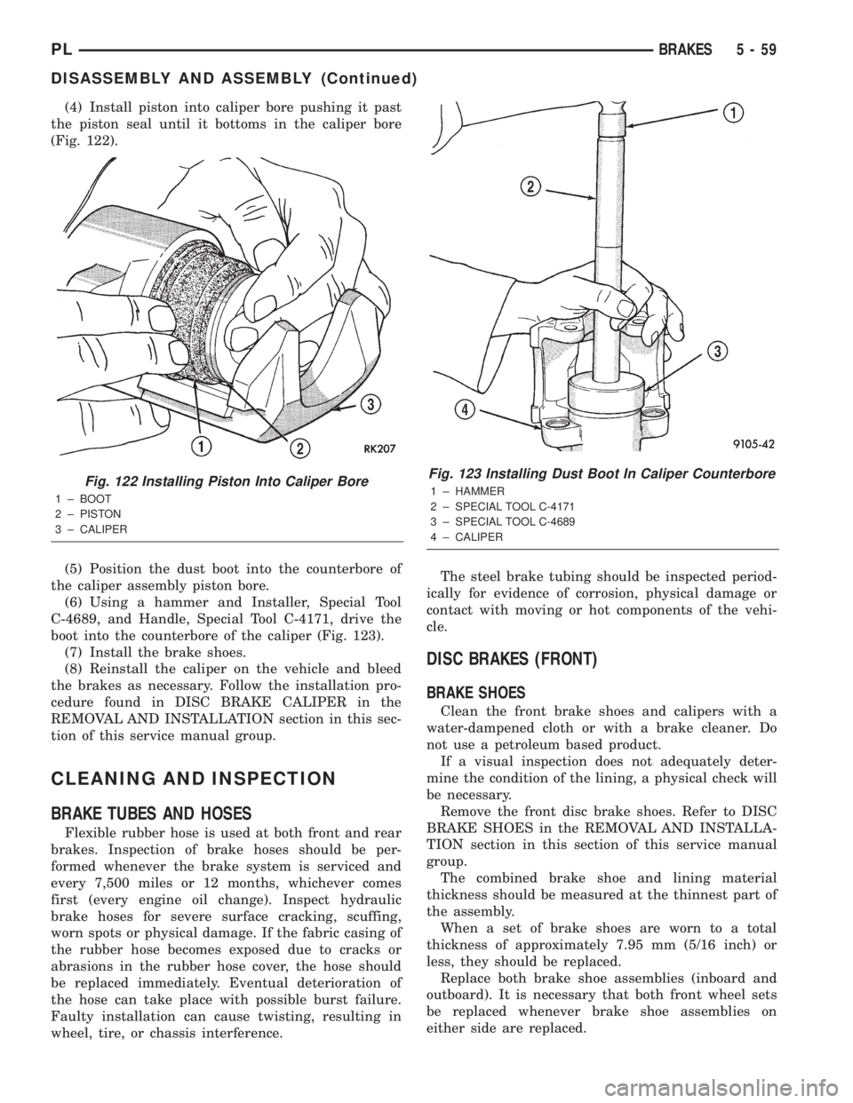
the piston seal until it bottoms in the caliper bore
(Fig. 122).
(5) Position the dust boot into the counterbore of
the caliper assembly piston bore.
(6) Using a hammer and Installer, Special Tool
C-4689, and Handle, Special Tool C-4171, drive the
boot into the counterbore of the caliper (Fig. 123).
(7) Install the brake shoes.
(8) Reinstall the caliper on the vehicle and bleed
the brakes as necessary. Follow the installation pro-
cedure found in DISC BRAKE CALIPER in the
REMOVAL AND INSTALLATION section in this sec-
tion of this service manual group.
CLEANING AND INSPECTION
BRAKE TUBES AND HOSES
Flexible rubber hose is used at both front and rear
brakes. Inspection of brake hoses should be per-
formed whenever the brake system is serviced and
every 7,500 miles or 12 months, whichever comes
first (every engine oil change). Inspect hydraulic
brake hoses for severe surface cracking, scuffing,
worn spots or physical damage. If the fabric casing of
the rubber hose becomes exposed due to cracks or
abrasions in the rubber hose cover, the hose should
be replaced immediately. Eventual deterioration of
the hose can take place with possible burst failure.
Faulty installation can cause twisting, resulting in
wheel, tire, or chassis interference.The steel brake tubing should be inspected period-
ically for evidence of corrosion, physical damage or
contact with moving or hot components of the vehi-
cle.
DISC BRAKES (FRONT)
BRAKE SHOES
Clean the front brake shoes and calipers with a
water-dampened cloth or with a brake cleaner. Do
not use a petroleum based product.
If a visual inspection does not adequately deter-
mine the condition of the lining, a physical check will
be necessary.
Remove the front disc brake shoes. Refer to DISC
BRAKE SHOES in the REMOVAL AND INSTALLA-
TION section in this section of this service manual
group.
The combined brake shoe and lining material
thickness should be measured at the thinnest part of
the assembly.
When a set of brake shoes are worn to a total
thickness of approximately 7.95 mm (5/16 inch) or
less, they should be replaced.
Replace both brake shoe assemblies (inboard and
outboard). It is necessary that both front wheel sets
be replaced whenever brake shoe assemblies on
either side are replaced.
Fig. 122 Installing Piston Into Caliper Bore
1 ± BOOT
2 ± PISTON
3 ± CALIPER
Fig. 123 Installing Dust Boot In Caliper Counterbore
1 ± HAMMER
2 ± SPECIAL TOOL C-4171
3 ± SPECIAL TOOL C-4689
4 ± CALIPER
PLBRAKES 5 - 59
DISASSEMBLY AND ASSEMBLY (Continued)
Page 139 of 1285
If the brake shoe assemblies do not require
replacement, reinstall the assemblies making sure
each brake shoe is returned to the original position.
Refer to DISC BRAKE SHOES in the REMOVAL
AND INSTALLATION section in this section of this
service manual group.
CALIPER INSPECTION
Check for brake fluid leaks in and around the boot
area. Check for any ruptures, brittleness or damage
to the piston dust boot. If the boot is damaged, or a
fluid leak is visible, disassemble the caliper assembly
and install a new seal and boot, and a piston if it is
scored. Refer to DISC BRAKE CALIPER in the DIS-
ASSEMBLY AND ASSEMBLY section in this section
of this service manual group.
Check the guide pin dust boots to determine if they
are in good condition. Replace if they are damaged,
dry, or found to be brittle. Refer to DISC BRAKE
CALIPER in the DISASSEMBLY AND ASSEMBLY
section in this section of this service manual group.
DISC BRAKES (REAR)
BRAKE SHOES
Clean the rear brake shoes and calipers with a
water-dampened cloth or with a brake cleaner. Do
not use a petroleum based product.
If a visual inspection does not adequately deter-
mine the condition of the lining, a physical check will
be necessary.
Remove the rear disc brake shoes. Refer to DISC
BRAKE SHOES in the REMOVAL AND INSTALLA-
TION section in this section of this service manual
group.
The combined brake shoe and lining material
thickness should be measured at the thinnest part of
the assembly.
When a set of brake shoes are worn to a total
thickness of approximately 7.0 mm (9/32 inch) or
less, they should be replaced.
Replace both brake shoe assemblies (inboard and
outboard). It is necessary that both front wheel sets
be replaced whenever brake shoe assemblies on
either side are replaced.
If the brake shoe assemblies do not require
replacement, reinstall the assemblies making sure
each brake shoe is returned to the original position.
Refer to DISC BRAKE SHOES in the REMOVAL
AND INSTALLATION section in this section of this
service manual group.
CALIPER INSPECTION
Check for brake fluid leaks in and around the boot
area. Check for any ruptures, brittleness or damage
to the piston dust boot. If the boot is damaged, or afluid leak is visible, disassemble the caliper assembly
and install a new seal and boot, and a piston if it is
scored. Refer to DISC BRAKE CALIPER in the DIS-
ASSEMBLY AND ASSEMBLY section in this section
of this service manual group.
Check the guide pin dust boots to determine if they
are in good condition. Replace if they are damaged,
dry, or found to be brittle. Refer to DISC BRAKE
CALIPER in the DISASSEMBLY AND ASSEMBLY
section in this section of this service manual group.
DRUM BRAKES (REAR)
BRAKE SHOES
Clean the rear brake shoes and springs with a
water-dampened cloth or with a brake cleaner. Do
not use a petroleum based product.
Rear brake shoe lining should show contact across
the entire width of the lining and also from the heel
to the toe of the lining. Replace the shoes if noted
otherwise.
Brake shoes with lack of contact at the toe or heel
of the brake shoe lining may be improperly ground.
Clean and inspect the brake support plate and
shoe adjuster screw. Apply a thin coat of Mopart
Multi-Purpose Lubricant or equivalent to the threads
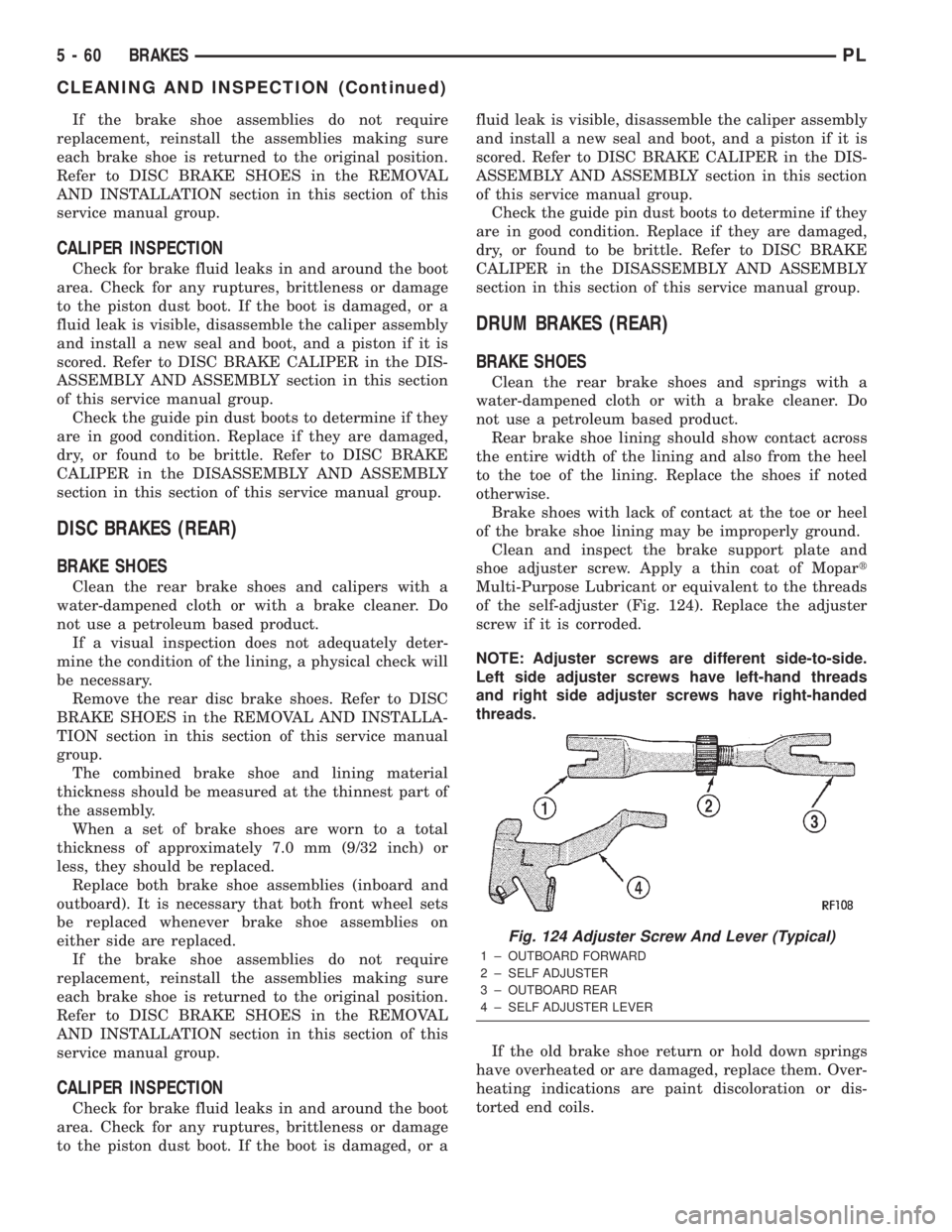
of the self-adjuster (Fig. 124). Replace the adjuster
screw if it is corroded.
NOTE: Adjuster screws are different side-to-side.
Left side adjuster screws have left-hand threads
and right side adjuster screws have right-handed
threads.
If the old brake shoe return or hold down springs
have overheated or are damaged, replace them. Over-
heating indications are paint discoloration or dis-
torted end coils.
Fig. 124 Adjuster Screw And Lever (Typical)
1 ± OUTBOARD FORWARD
2 ± SELF ADJUSTER
3 ± OUTBOARD REAR
4 ± SELF ADJUSTER LEVER
5 - 60 BRAKESPL
CLEANING AND INSPECTION (Continued)
Page 140 of 1285
WHEEL CYLINDER
With the brake drums removed, inspect the wheel
cylinder boots for evidence of a brake fluid leak.
Visually check the boots for cuts, tears, or heat
cracks. If any of these conditions exist, the wheel cyl-
inders should be completely cleaned, inspected and
new parts installed.
If a wheel cylinder is leaking and the brake lining
material is saturated with brake fluid, the brake
shoes must be replaced.
ADJUSTMENTS
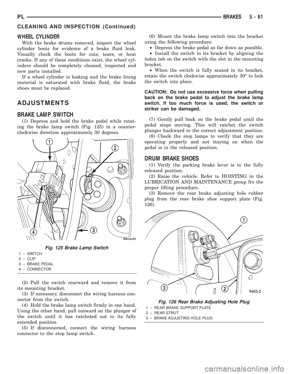
BRAKE LAMP SWITCH
(1) Depress and hold the brake pedal while rotat-
ing the brake lamp switch (Fig. 125) in a counter-
clockwise direction approximately 30 degrees.
(2) Pull the switch rearward and remove it from
its mounting bracket.
(3) If necessary, disconnect the wiring harness con-
nector from the switch.
(4) Hold the brake lamp switch firmly in one hand.
Using the other hand, pull outward on the plunger of
the switch until it has ratcheted out to its fully
extended position.
(5) If disconnected, connect the wiring harness
connector to the stop lamp switch.(6) Mount the brake lamp switch into the bracket
using the following procedure:
²Depress the brake pedal as far down as possible.
²Install the switch in its bracket by aligning the
index tab on the switch with the slot in the mounting
bracket.
²When the switch is fully seated in its bracket,
rotate the switch clockwise approximately 30É to lock
the switch into place.
CAUTION: Do not use excessive force when pulling
back on the brake pedal to adjust the brake lamp
switch. If too much force is used, the switch or
striker can be damaged.
(7) Gently pull back on the brake pedal until the
pedal stops moving. This will ratchet the switch
plunger backward to the correct adjustment position.
(8) Check the stop lamps to verify that they are
operating properly and not staying on when the
pedal is in the released position.
DRUM BRAKE SHOES
(1) Verify the parking brake lever is in the fully
released position.
(2) Raise the vehicle. Refer to HOISTING in the
LUBRICATION AND MAINTENANCE group fro the
proper lifting procedure.
(3) Remove the rear brake adjusting hole rubber
plug from the rear brake shoe support plate (Fig.
126).
Fig. 125 Brake Lamp Switch
1 ± SWITCH
2 ± CLIP
3 ± BRAKE PEDAL
4 ± CONNECTOR
Fig. 126 Rear Brake Adjusting Hole Plug
1 ± REAR BRAKE SUPPORT PLATE
2 ± REAR STRUT
3 ± BRAKE ADJUSTING HOLE PLUG
PLBRAKES 5 - 61
CLEANING AND INSPECTION (Continued)
Page 143 of 1285
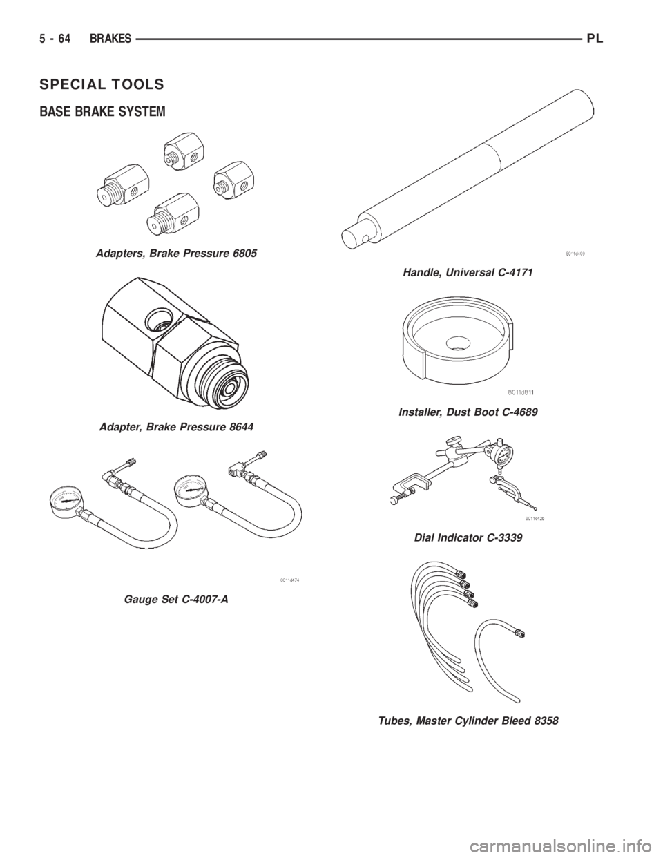
SPECIAL TOOLS
BASE BRAKE SYSTEM
Adapters, Brake Pressure 6805
Adapter, Brake Pressure 8644
Gauge Set C-4007-A
Handle, Universal C-4171
Installer, Dust Boot C-4689
Dial Indicator C-3339
Tubes, Master Cylinder Bleed 8358
5 - 64 BRAKESPL
Page 217 of 1285
²It passes the 15 second load test. Refer to Bat-
tery Load Test.
²The built in test indicator dot is GREEN (Fig.
2).
NOTE: The battery cannot be refilled with water, it
must be replaced.
WARNING: DO NOT CHARGE A BATTERY THAT
HAS EXCESSIVELY LOW ELECTROLYTE LEVEL.
BATTERY MAY SPARK INTERNALLY AND
EXPLODE. EXPLOSIVE GASES FORM OVER THE
BATTERY. DO NOT SMOKE, USE FLAME, OR CRE-
ATE SPARKS NEAR BATTERY. DO NOT ASSIST
BOOST OR CHARGE A FROZEN BATTERY. BAT-
TERY CASING MAY FRACTURE. BATTERY ACID IS
POISON, AND MAY CAUSE SEVERE BURNS. BAT-
TERIES CONTAIN SULFURIC ACID. AVOID CON-
TACT WITH SKIN, EYES, OR CLOTHING. IN THE
EVENT OF CONTACT, FLUSH WITH WATER AND
CALL PHYSICIAN IMMEDIATELY. KEEP OUT OF
REACH OF CHILDREN.
CAUTION: Disconnect the battery NEGATIVE cable
first, before charging battery to avoid damage to
electrical systems. Lift the red battery boot cover
from the positive cable clamp. Do not exceed 16.0
volts while charging battery. Refer to the instruc-
tions supplied with charging equipment
Battery electrolyte may bubble inside of battery
case while being charged properly. If the electrolyte
boils violently, or is discharged from the vent holes
while charging, immediately reduce charging rate or
turn off charger. Evaluate battery condition. Battery
damage may occur if charging is excessive.
Some battery chargers are equipped with polarity
sensing devices to protect the charger or battery from
being damaged if improperly connected. If the bat-
tery state of charge is too low for the polarity sensor
to detect, the sensor must be bypassed for charger to
operate. Refer to operating instructions provided
with battery charger being used.
CAUTION: Charge battery until test indicator
appears green. Do not overcharge.
It may be necessary to jiggle the battery or vehicle
to bring the green dot in the test indicator into view.
After the battery has been charged to 12.4 volts or
greater, perform a load test to determine cranking
capacity. Refer to Battery Load Test in this Group. If
the battery passes the load test, the battery is OK to
use. If battery will not pass the load test, it must be
replaced. Properly clean and inspect battery holddowns, tray, terminals, cables, posts, and top before
completing service.
CHARGING COMPLETELY DISCHARGED
BATTERY
The following procedure should be used to recharge
a completely discharged battery. Unless procedure is
properly followed, a good battery may be needlessly
replaced. Refer to Battery Charging Rate Table for
proper charging time.
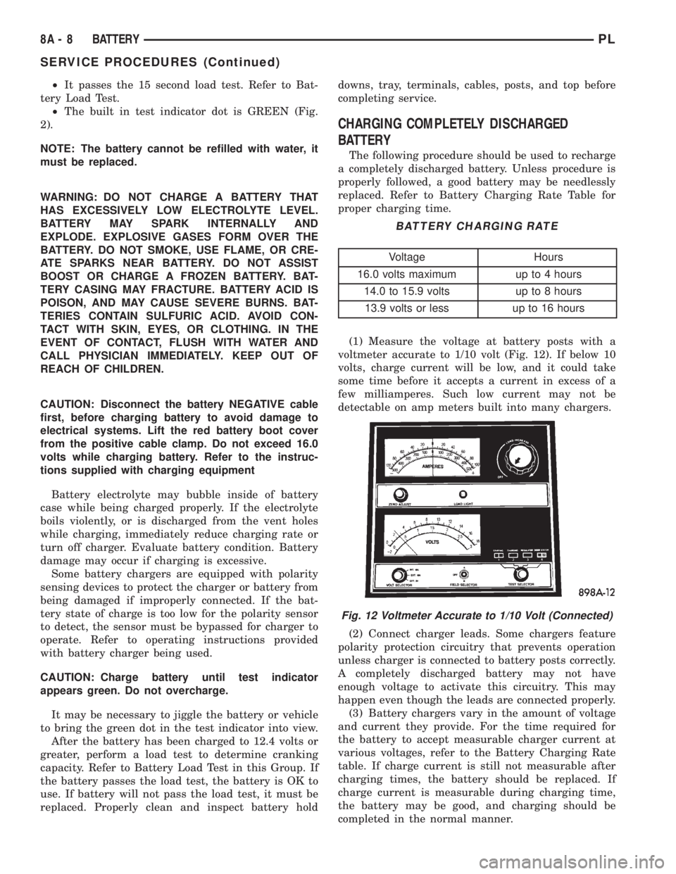
(1) Measure the voltage at battery posts with a
voltmeter accurate to 1/10 volt (Fig. 12). If below 10
volts, charge current will be low, and it could take
some time before it accepts a current in excess of a
few milliamperes. Such low current may not be
detectable on amp meters built into many chargers.
(2) Connect charger leads. Some chargers feature
polarity protection circuitry that prevents operation
unless charger is connected to battery posts correctly.
A completely discharged battery may not have
enough voltage to activate this circuitry. This may
happen even though the leads are connected properly.
(3) Battery chargers vary in the amount of voltage
and current they provide. For the time required for
the battery to accept measurable charger current at
various voltages, refer to the Battery Charging Rate
table. If charge current is still not measurable after
charging times, the battery should be replaced. If
charge current is measurable during charging time,
the battery may be good, and charging should be
completed in the normal manner.
BATTERY CHARGING RATE
Voltage Hours
16.0 volts maximum up to 4 hours
14.0 to 15.9 volts up to 8 hours
13.9 volts or less up to 16 hours
Fig. 12 Voltmeter Accurate to 1/10 Volt (Connected)
8A - 8 BATTERYPL
SERVICE PROCEDURES (Continued)
Page 236 of 1285
IGNITION SYSTEM
TABLE OF CONTENTS
page page
DESCRIPTION AND OPERATION
IGNITION SYSTEM........................1
SPARK PLUGS...........................1
SPARK PLUG CABLES.....................1
ELECTRONIC IGNITION COILS...............2
AUTOMATIC SHUTDOWN RELAY.............2
CRANKSHAFT POSITION SENSORÐPCM
INPUT................................3
CAMSHAFT POSITION SENSORÐPCM
INPUT................................4
KNOCK SENSOR..........................5
IGNITION SWITCH........................5
LOCK KEY CYLINDER......................5
IGNITION INTERLOCK.....................6
REMOVAL AND INSTALLATION
SPARK PLUG SERVICE....................6SPARK PLUG CABLE SERVICE..............6
IGNITION COIL...........................6
AUTOMATIC SHUTDOWN RELAY.............6
CAMSHAFT POSITION SENSOR..............6
CRANKSHAFT POSITION SENSOR............8
KNOCK SENSOR..........................8
IGNITION SWITCH........................8
LOCK KEY CYLINDER......................9
IGNITION INTERLOCK....................10
SPECIFICATIONS
VECI LABEL............................10
FIRING ORDERÐ2.0L....................10
TORQUE SPECIFICATION..................11
SPARK PLUG CABLE RESISTANCEÐSOHC....11
SPARK PLUG...........................11
IGNITION COIL..........................11
DESCRIPTION AND OPERATION
IGNITION SYSTEM
DESCRIPTION
The system's three main components are the coil
pack, crankshaft position sensor, and camshaft posi-
tion sensor.
OPERATION
Basic ignition timing is not adjustable.The
Powertrain Control Module (PCM) determines spark
advance. The 2.0L engines use a fixed ignition timing
system. The distributorless electronic ignition system
is referred to as the Direct Ignition System (DIS).
SPARK PLUGS
The 2.0L engines uses resistor spark plugs. For
spark plug identification and specifications, Refer to
the Specifications section at the end of this group.
Remove the spark plugs and examine them for
burned electrodes and fouled, cracked or broken por-
celain insulators. Keep plugs arranged in the order
in which they were removed from the engine. An iso-
lated plug displaying an abnormal condition indicates
that a problem exists in the corresponding cylinder.
Spark plugs that have low mileage may be cleaned
and reused if not otherwise defective. Refer to the
Spark Plug Condition section of this group. Aftercleaning, file the center electrode flat with a small
point file or jewelers file. Adjust the gap between the
electrodes (Fig. 1) to the dimensions specified in the
chart at the end of this section by bending the
ground electrode (just above the attachment weld)
with the appropriate tool.
Never apply any force between the electrode or
damage to the center electrode assembly will result.
Always tighten spark plugs to the specified torque.
Over tightening can cause distortion and damage.
Tighten spark plugs to 28 N´m (20 ft. lbs.) torque.
SPARK PLUG CABLES
Spark plug cables are sometimes referred to as sec-
ondary ignition wires. The wires transfer electrical
current from the coil pack to individual spark plugs
at each cylinder. The resistor type, nonmetallic spark
plug cables provide suppression of radio frequency
emissions from the ignition system.
Check the spark plug cable connections for good
contact at the coil and spark plugs. Terminals should
be fully seated. The nipples and spark plug covers
should be in good condition. Nipples should fit tightly
on the coil. Spark plug boot should completely cover
the spark plug hole in the cylinder head cover. Install
the boot until the terminal snaps over the spark
plug. A snap must be felt to ensure the spark plug
cable terminal engaged the spark plug.
PLIGNITION SYSTEM 8D - 1