2000 DODGE NEON boot
[x] Cancel search: bootPage 74 of 1285
(13) Install the driveshaft requiring boot replace-
ment back on the vehicle. See Driveshaft Removal
and Installation in this section for the required drive-
shaft installation procedure.
OUTER C/V JOINT SEAL BOOT
REMOVAL
To remove outer C/V joint sealing boot from a drive-
shaft for replacement, the driveshaft assembly must
be removed from the vehicle. See Driveshaft Removal
and Installation in this section for the required drive-
shaft removal and replacement procedure.
(1) Remove driveshaft assembly requiring boot
replacement from vehicle. See Driveshaft Removal
and Installation in this section for the required drive-
shaft removal procedure.
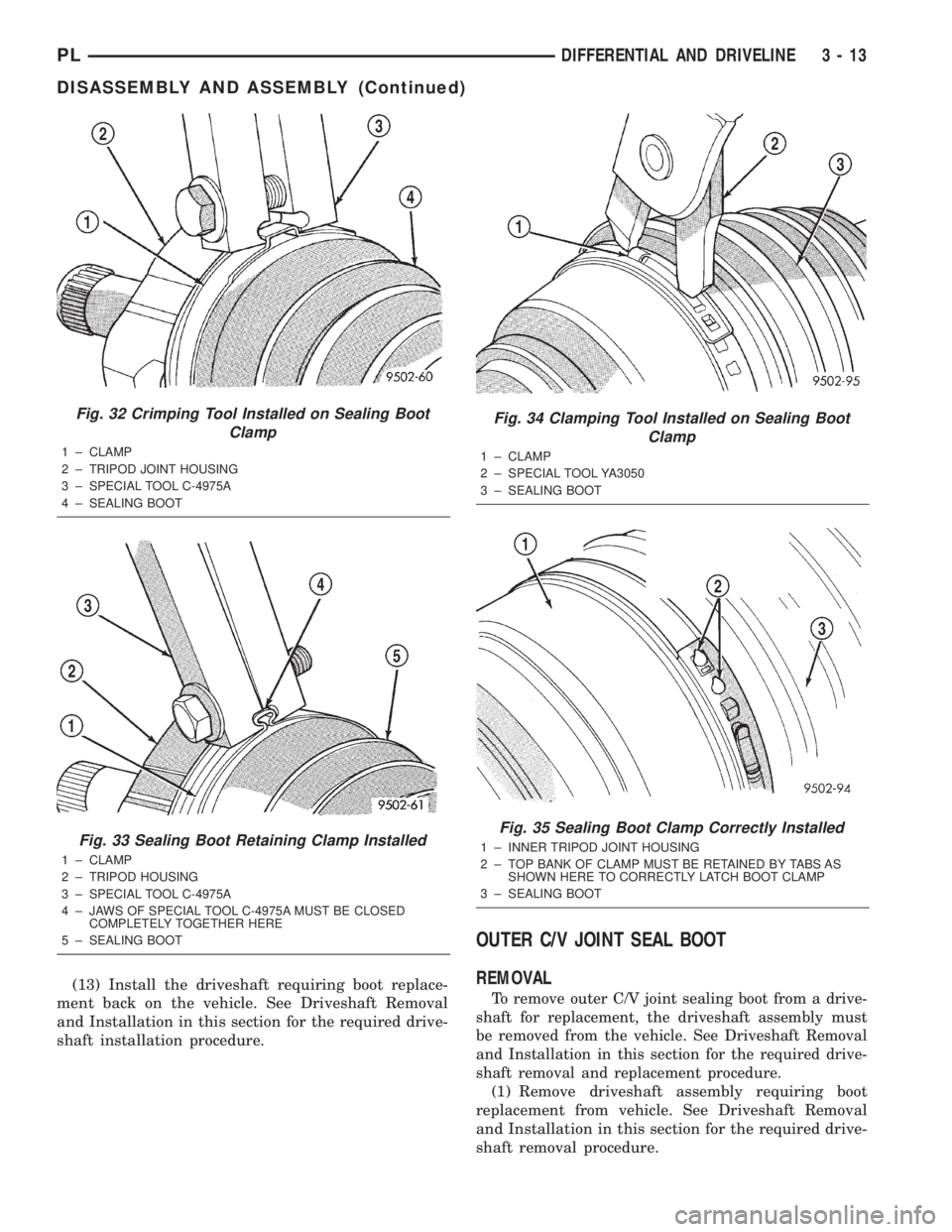
Fig. 32 Crimping Tool Installed on Sealing Boot
Clamp
1 ± CLAMP
2 ± TRIPOD JOINT HOUSING
3 ± SPECIAL TOOL C-4975A
4 ± SEALING BOOT
Fig. 33 Sealing Boot Retaining Clamp Installed
1 ± CLAMP
2 ± TRIPOD HOUSING
3 ± SPECIAL TOOL C-4975A
4 ± JAWS OF SPECIAL TOOL C-4975A MUST BE CLOSED
COMPLETELY TOGETHER HERE
5 ± SEALING BOOT
Fig. 34 Clamping Tool Installed on Sealing Boot
Clamp
1 ± CLAMP
2 ± SPECIAL TOOL YA3050
3 ± SEALING BOOT
Fig. 35 Sealing Boot Clamp Correctly Installed
1 ± INNER TRIPOD JOINT HOUSING
2 ± TOP BANK OF CLAMP MUST BE RETAINED BY TABS AS
SHOWN HERE TO CORRECTLY LATCH BOOT CLAMP
3 ± SEALING BOOT
PLDIFFERENTIAL AND DRIVELINE 3 - 13
DISASSEMBLY AND ASSEMBLY (Continued)
Page 75 of 1285
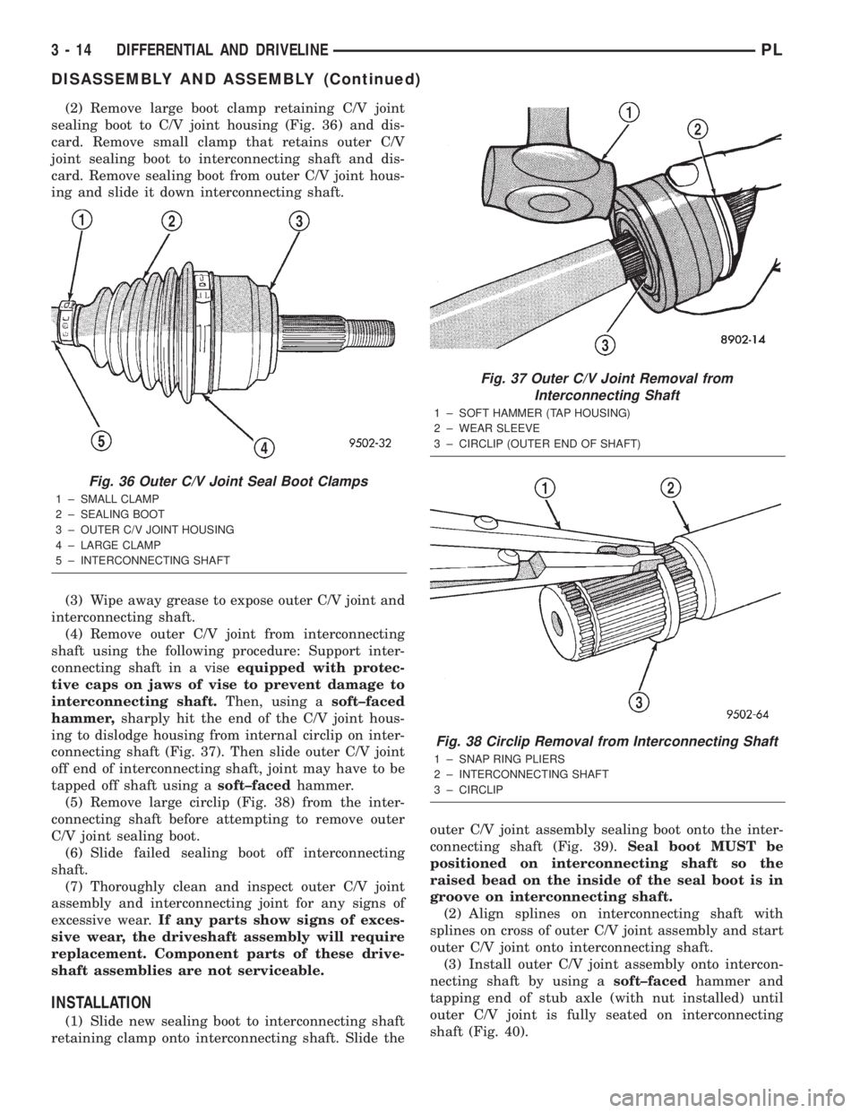
(2) Remove large boot clamp retaining C/V joint
sealing boot to C/V joint housing (Fig. 36) and dis-
card. Remove small clamp that retains outer C/V
joint sealing boot to interconnecting shaft and dis-
card. Remove sealing boot from outer C/V joint hous-
ing and slide it down interconnecting shaft.
(3) Wipe away grease to expose outer C/V joint and
interconnecting shaft.
(4) Remove outer C/V joint from interconnecting
shaft using the following procedure: Support inter-
connecting shaft in a viseequipped with protec-
tive caps on jaws of vise to prevent damage to
interconnecting shaft.Then, using asoft±faced
hammer,sharply hit the end of the C/V joint hous-
ing to dislodge housing from internal circlip on inter-
connecting shaft (Fig. 37). Then slide outer C/V joint
off end of interconnecting shaft, joint may have to be
tapped off shaft using asoft±facedhammer.
(5) Remove large circlip (Fig. 38) from the inter-
connecting shaft before attempting to remove outer
C/V joint sealing boot.
(6) Slide failed sealing boot off interconnecting
shaft.
(7) Thoroughly clean and inspect outer C/V joint
assembly and interconnecting joint for any signs of
excessive wear.If any parts show signs of exces-
sive wear, the driveshaft assembly will require
replacement. Component parts of these drive-
shaft assemblies are not serviceable.
INSTALLATION
(1) Slide new sealing boot to interconnecting shaft
retaining clamp onto interconnecting shaft. Slide theouter C/V joint assembly sealing boot onto the inter-
connecting shaft (Fig. 39).Seal boot MUST be
positioned on interconnecting shaft so the
raised bead on the inside of the seal boot is in
groove on interconnecting shaft.
(2) Align splines on interconnecting shaft with
splines on cross of outer C/V joint assembly and start
outer C/V joint onto interconnecting shaft.
(3) Install outer C/V joint assembly onto intercon-
necting shaft by using asoft±facedhammer and
tapping end of stub axle (with nut installed) until
outer C/V joint is fully seated on interconnecting
shaft (Fig. 40).
Fig. 36 Outer C/V Joint Seal Boot Clamps
1 ± SMALL CLAMP
2 ± SEALING BOOT
3 ± OUTER C/V JOINT HOUSING
4 ± LARGE CLAMP
5 ± INTERCONNECTING SHAFT
Fig. 37 Outer C/V Joint Removal from
Interconnecting Shaft
1 ± SOFT HAMMER (TAP HOUSING)
2 ± WEAR SLEEVE
3 ± CIRCLIP (OUTER END OF SHAFT)
Fig. 38 Circlip Removal from Interconnecting Shaft
1 ± SNAP RING PLIERS
2 ± INTERCONNECTING SHAFT
3 ± CIRCLIP
3 - 14 DIFFERENTIAL AND DRIVELINEPL
DISASSEMBLY AND ASSEMBLY (Continued)
Page 76 of 1285
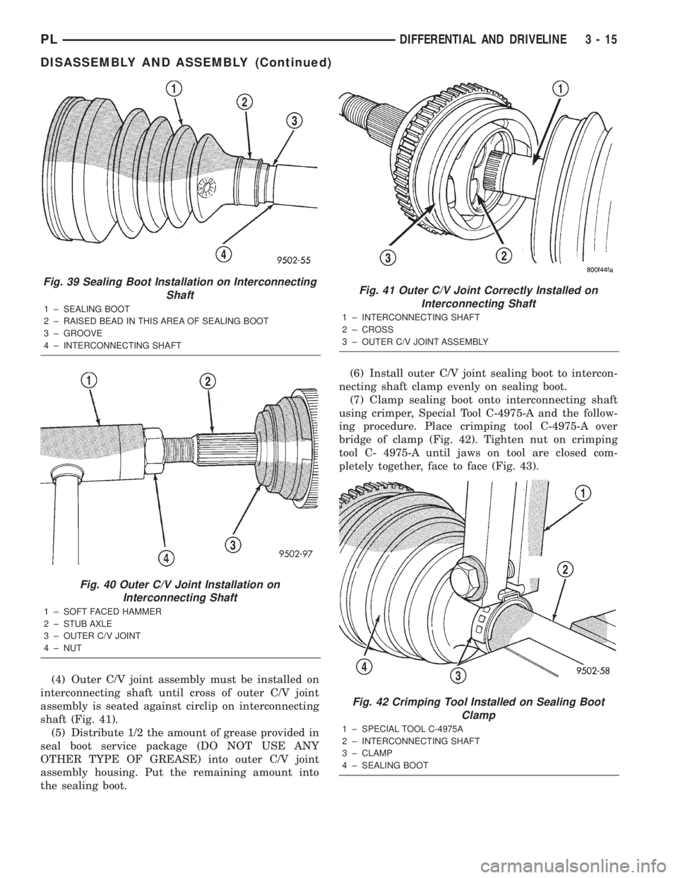
(4) Outer C/V joint assembly must be installed on
interconnecting shaft until cross of outer C/V joint
assembly is seated against circlip on interconnecting
shaft (Fig. 41).
(5) Distribute 1/2 the amount of grease provided in
seal boot service package (DO NOT USE ANY
OTHER TYPE OF GREASE) into outer C/V joint
assembly housing. Put the remaining amount into
the sealing boot.(6) Install outer C/V joint sealing boot to intercon-
necting shaft clamp evenly on sealing boot.
(7) Clamp sealing boot onto interconnecting shaft
using crimper, Special Tool C-4975-A and the follow-
ing procedure. Place crimping tool C-4975-A over
bridge of clamp (Fig. 42). Tighten nut on crimping
tool C- 4975-A until jaws on tool are closed com-
pletely together, face to face (Fig. 43).
Fig. 39 Sealing Boot Installation on Interconnecting
Shaft
1 ± SEALING BOOT
2 ± RAISED BEAD IN THIS AREA OF SEALING BOOT
3 ± GROOVE
4 ± INTERCONNECTING SHAFT
Fig. 40 Outer C/V Joint Installation on
Interconnecting Shaft
1 ± SOFT FACED HAMMER
2 ± STUB AXLE
3 ± OUTER C/V JOINT
4 ± NUT
Fig. 41 Outer C/V Joint Correctly Installed on
Interconnecting Shaft
1 ± INTERCONNECTING SHAFT
2 ± CROSS
3 ± OUTER C/V JOINT ASSEMBLY
Fig. 42 Crimping Tool Installed on Sealing Boot
Clamp
1 ± SPECIAL TOOL C-4975A
2 ± INTERCONNECTING SHAFT
3 ± CLAMP
4 ± SEALING BOOT
PLDIFFERENTIAL AND DRIVELINE 3 - 15
DISASSEMBLY AND ASSEMBLY (Continued)
Page 77 of 1285
CAUTION: Seal must not be dimpled, stretched, or
out±of±shape in any way. If seal is NOT shaped cor-
rectly, equalize pressure in seal and shape it by
hand.
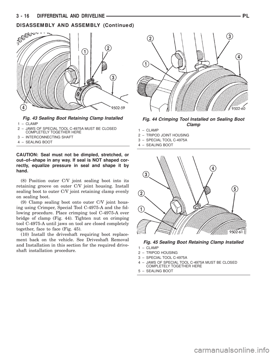
(8) Position outer C/V joint sealing boot into its
retaining groove on outer C/V joint housing. Install
sealing boot to outer C/V joint retaining clamp evenly
on sealing boot.
(9) Clamp sealing boot onto outer C/V joint hous-
ing using Crimper, Special Tool C-4975-A and the fol-
lowing procedure. Place crimping tool C-4975-A over
bridge of clamp (Fig. 44). Tighten nut on crimping
tool C-4975-A until jaws on tool are closed completely
together, face to face (Fig. 45).
(10) Install the driveshaft requiring boot replace-
ment back on the vehicle. See Driveshaft Removal
and Installation in this section for the required drive-
shaft installation procedure.
Fig. 43 Sealing Boot Retaining Clamp Installed
1 ± CLAMP
2 ± JAWS OF SPECIAL TOOL C-4975A MUST BE CLOSED
COMPLETELY TOGETHER HERE
3 ± INTERCONNECTING SHAFT
4 ± SEALING BOOTFig. 44 Crimping Tool Installed on Sealing Boot
Clamp
1 ± CLAMP
2 ± TRIPOD JOINT HOUSING
3 ± SPECIAL TOOL C-4975A
4 ± SEALING BOOT
Fig. 45 Sealing Boot Retaining Clamp Installed
1 ± CLAMP
2 ± TRIPOD HOUSING
3 ± SPECIAL TOOL C-4975A
4 ± JAWS OF SPECIAL TOOL C-4975A MUST BE CLOSED
COMPLETELY TOGETHER HERE
5 ± SEALING BOOT
3 - 16 DIFFERENTIAL AND DRIVELINEPL
DISASSEMBLY AND ASSEMBLY (Continued)
Page 78 of 1285
SPECIFICATIONS
TORQUE
DESCRIPTION TORQUE
Driveshaft-to-Hub/Bearing
Nut................... 244N´m(180 ft. lbs.)
Knuckle-to-Ball Joint
Bolt/Nut................. 95N´m(70ft.lbs.)
Wheel/Tire-to-Hub/Bearing
Lug Nuts............... 128N´m(95ft.lbs.)
SPECIAL TOOLS
DRIVESHAFT
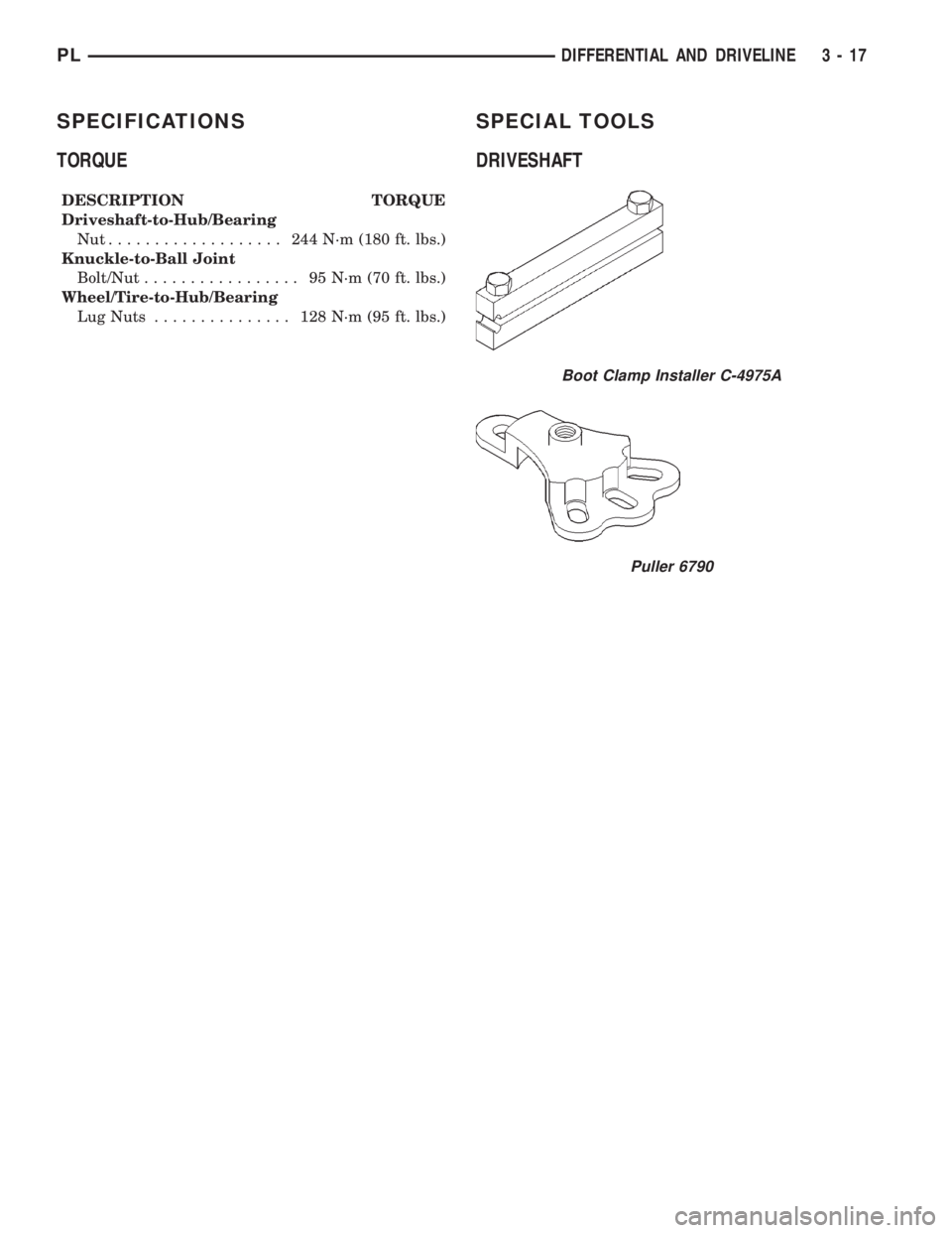
Boot Clamp Installer C-4975A
Puller 6790
PLDIFFERENTIAL AND DRIVELINE 3 - 17
Page 83 of 1285
Proportioning valves balance front to rear braking
by controlling the brake fluid hydraulic pressure to
the rear brakes. Under light pedal application, the
proportioning valve allows normal fluid flow to the
rear brakes. Under higher pedal effort, the valve
reduces fluid pressure to the rear brakes.
The non-antilock master cylinder is a four-outlet
design with two screw-in proportioning valves
attached directly to the master cylinder housing (Fig.
3). One proportioning valve controls each rear brake.
BRAKE TUBES AND HOSES
The purpose of the brake tubes and flex hoses is to
transfer the pressurized brake fluid developed by the
master cylinder to the brakes at each wheel of the
vehicle. The flex hoses connect the chassis brake
tubes, which are mounted to the vehicle's underbody,
to the brake at each wheel, allowing for movement of
the vehicle's suspension. The brake tubes are steel
with a corrosion-resistant nylon coating applied to
the external surfaces. The flex hoses are made of
reinforced rubber.
DISC BRAKES (FRONT)
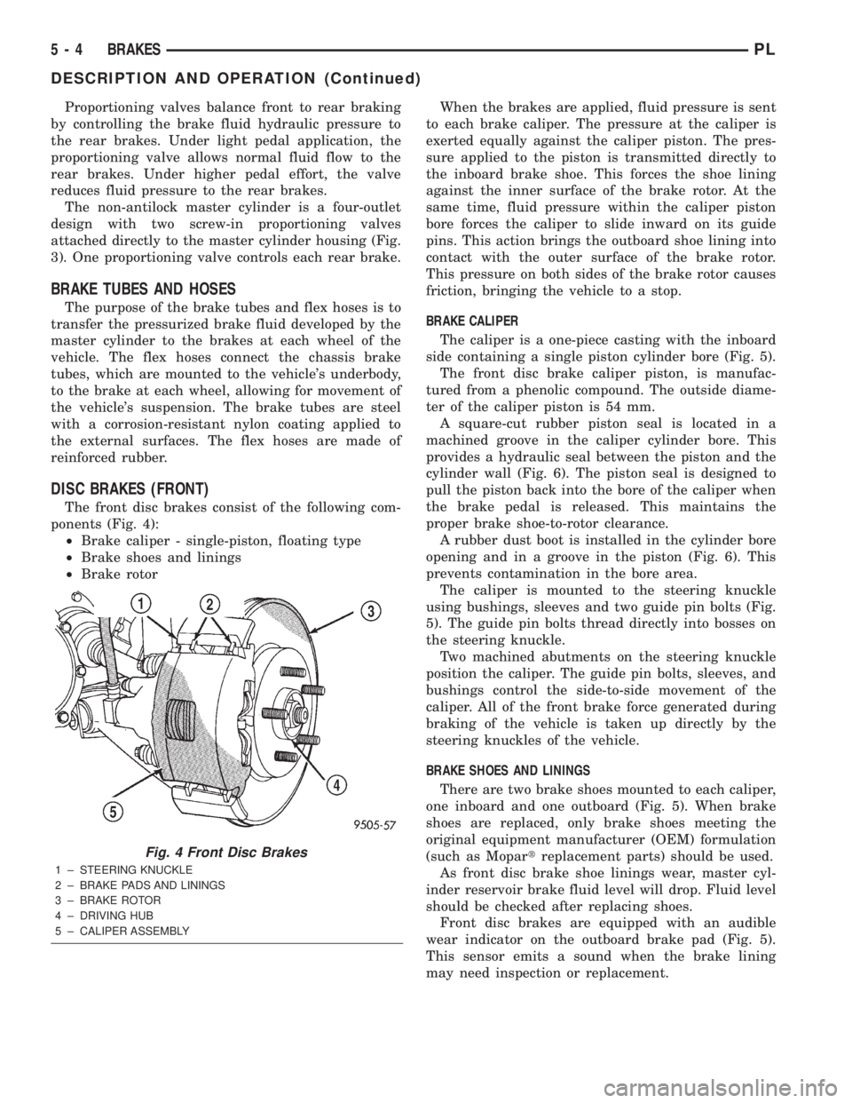
The front disc brakes consist of the following com-
ponents (Fig. 4):
²Brake caliper - single-piston, floating type
²Brake shoes and linings
²Brake rotorWhen the brakes are applied, fluid pressure is sent
to each brake caliper. The pressure at the caliper is
exerted equally against the caliper piston. The pres-
sure applied to the piston is transmitted directly to
the inboard brake shoe. This forces the shoe lining
against the inner surface of the brake rotor. At the
same time, fluid pressure within the caliper piston
bore forces the caliper to slide inward on its guide
pins. This action brings the outboard shoe lining into
contact with the outer surface of the brake rotor.
This pressure on both sides of the brake rotor causes
friction, bringing the vehicle to a stop.
BRAKE CALIPER
The caliper is a one-piece casting with the inboard
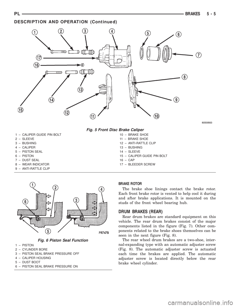
side containing a single piston cylinder bore (Fig. 5).
The front disc brake caliper piston, is manufac-
tured from a phenolic compound. The outside diame-
ter of the caliper piston is 54 mm.
A square-cut rubber piston seal is located in a
machined groove in the caliper cylinder bore. This
provides a hydraulic seal between the piston and the
cylinder wall (Fig. 6). The piston seal is designed to
pull the piston back into the bore of the caliper when
the brake pedal is released. This maintains the
proper brake shoe-to-rotor clearance.
A rubber dust boot is installed in the cylinder bore
opening and in a groove in the piston (Fig. 6). This
prevents contamination in the bore area.
The caliper is mounted to the steering knuckle
using bushings, sleeves and two guide pin bolts (Fig.
5). The guide pin bolts thread directly into bosses on
the steering knuckle.
Two machined abutments on the steering knuckle
position the caliper. The guide pin bolts, sleeves, and
bushings control the side-to-side movement of the
caliper. All of the front brake force generated during
braking of the vehicle is taken up directly by the
steering knuckles of the vehicle.
BRAKE SHOES AND LININGS
There are two brake shoes mounted to each caliper,
one inboard and one outboard (Fig. 5). When brake
shoes are replaced, only brake shoes meeting the
original equipment manufacturer (OEM) formulation
(such as Mopartreplacement parts) should be used.
As front disc brake shoe linings wear, master cyl-
inder reservoir brake fluid level will drop. Fluid level
should be checked after replacing shoes.
Front disc brakes are equipped with an audible
wear indicator on the outboard brake pad (Fig. 5).
This sensor emits a sound when the brake lining
may need inspection or replacement.
Fig. 4 Front Disc Brakes
1 ± STEERING KNUCKLE
2 ± BRAKE PADS AND LININGS
3 ± BRAKE ROTOR
4 ± DRIVING HUB
5 ± CALIPER ASSEMBLY
5 - 4 BRAKESPL
DESCRIPTION AND OPERATION (Continued)
Page 84 of 1285
BRAKE ROTOR
The brake shoe linings contact the brake rotor.
Each front brake rotor is vented to help cool it during
and after brake applications. It is mounted on the
studs of the front wheel bearing hub.
DRUM BRAKES (REAR)
Rear drum brakes are standard equipment on this
vehicle. The rear drum brakes consist of the major
components listed in the figure (Fig. 7). Other com-
ponents related to the brake shoes themselves can be
seen in the next figure (Fig. 8).
The rear wheel drum brakes are a two-shoe, inter-
nal-expanding type with an automatic adjuster screw
(Fig. 8). The automatic adjuster screw is actuated
each time the brakes are applied. The automatic
adjuster screw is located directly below the rear
brake wheel cylinder.
Fig. 5 Front Disc Brake Caliper
1 ± CALIPER GUIDE PIN BOLT
2 ± SLEEVE
3 ± BUSHING
4 ± CALIPER
5 ± PISTON SEAL
6 ± PISTON
7 ± DUST SEAL
8 ± WEAR INDICATOR
9 ± ANTI-RATTLE CLIP10 ± BRAKE SHOE
11 ± BRAKE SHOE
12 ± ANTI-RATTLE CLIP
13 ± BUSHING
14 ± SLEEVE
15 ± CALIPER GUIDE PIN BOLT
16 ± CAP
17 ± BLEEDER SCREW
Fig. 6 Piston Seal Function
1 ± PISTON
2 ± CYLINDER BORE
3 ± PISTON SEAL BRAKE PRESSURE OFF
4 ± CALIPER HOUSING
5 ± DUST BOOT
6 ± PISTON SEAL BRAKE PRESSURE ON
PLBRAKES 5 - 5
DESCRIPTION AND OPERATION (Continued)
Page 135 of 1285
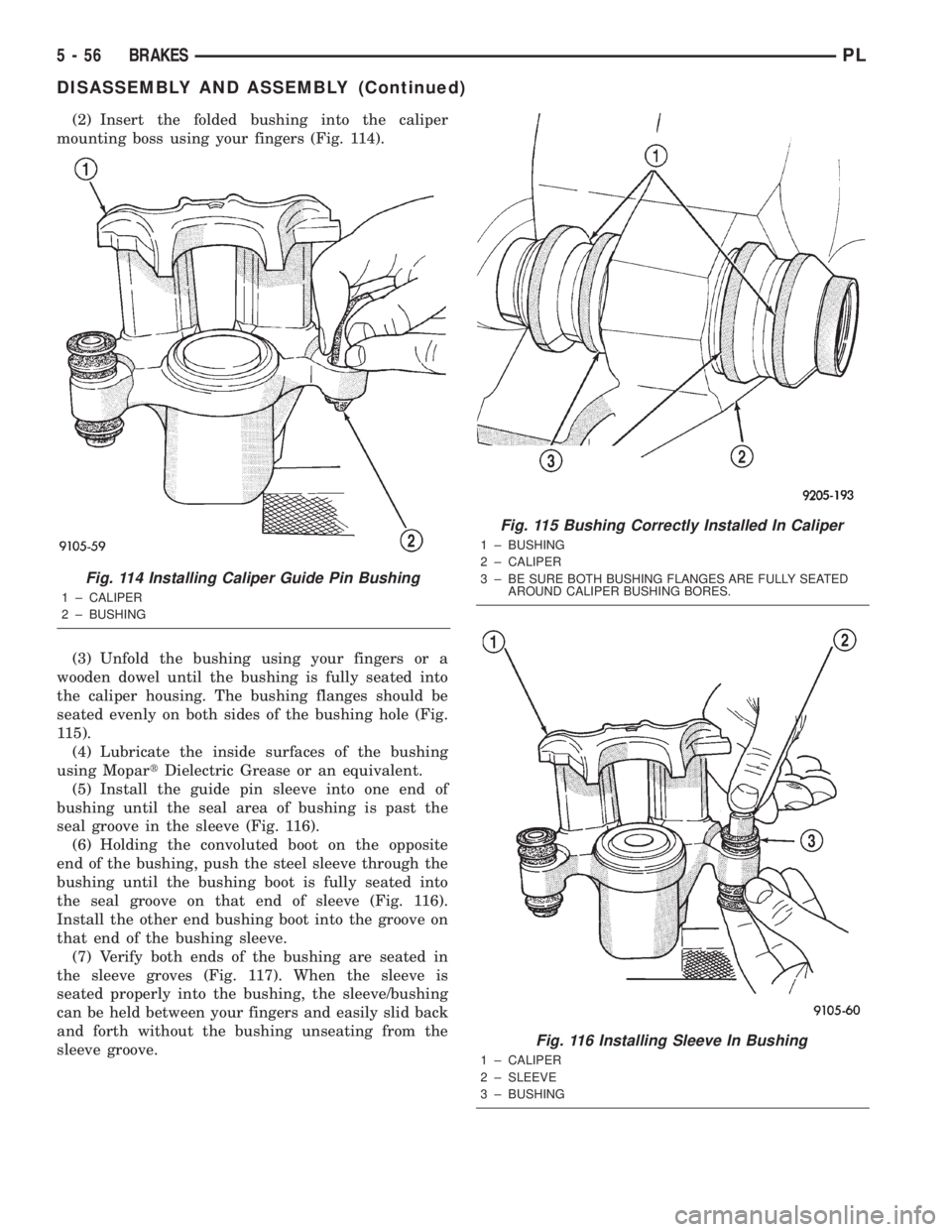
(2) Insert the folded bushing into the caliper
mounting boss using your fingers (Fig. 114).
(3) Unfold the bushing using your fingers or a
wooden dowel until the bushing is fully seated into
the caliper housing. The bushing flanges should be
seated evenly on both sides of the bushing hole (Fig.
115).
(4) Lubricate the inside surfaces of the bushing
using MopartDielectric Grease or an equivalent.
(5) Install the guide pin sleeve into one end of
bushing until the seal area of bushing is past the
seal groove in the sleeve (Fig. 116).
(6) Holding the convoluted boot on the opposite
end of the bushing, push the steel sleeve through the
bushing until the bushing boot is fully seated into
the seal groove on that end of sleeve (Fig. 116).
Install the other end bushing boot into the groove on
that end of the bushing sleeve.
(7) Verify both ends of the bushing are seated in
the sleeve groves (Fig. 117). When the sleeve is
seated properly into the bushing, the sleeve/bushing
can be held between your fingers and easily slid back
and forth without the bushing unseating from the
sleeve groove.
Fig. 114 Installing Caliper Guide Pin Bushing
1 ± CALIPER
2 ± BUSHING
Fig. 115 Bushing Correctly Installed In Caliper
1 ± BUSHING
2 ± CALIPER
3 ± BE SURE BOTH BUSHING FLANGES ARE FULLY SEATED
AROUND CALIPER BUSHING BORES.
Fig. 116 Installing Sleeve In Bushing
1 ± CALIPER
2 ± SLEEVE
3 ± BUSHING
5 - 56 BRAKESPL
DISASSEMBLY AND ASSEMBLY (Continued)