2000 DODGE NEON boot
[x] Cancel search: bootPage 918 of 1285
INSTALLATION
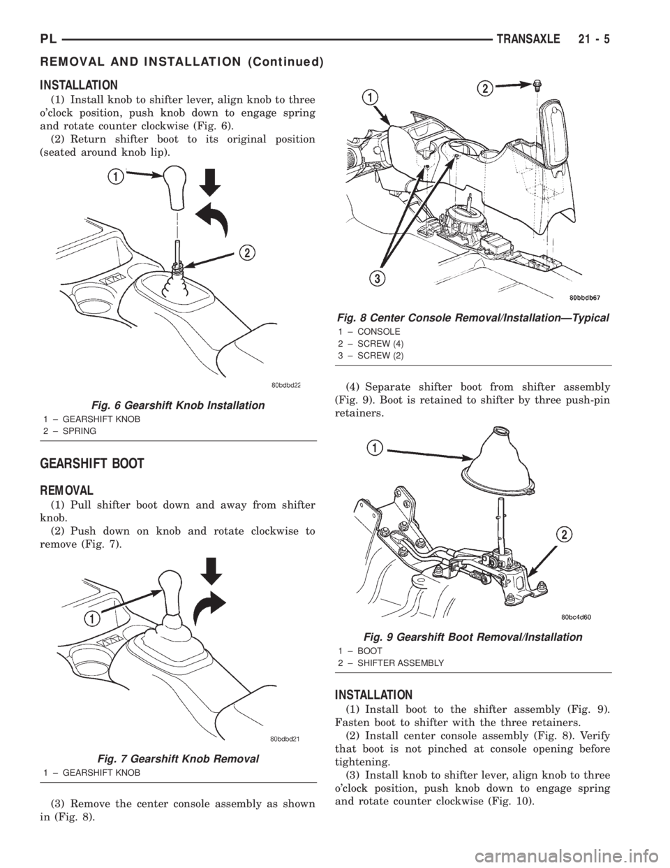
(1) Install knob to shifter lever, align knob to three
o'clock position, push knob down to engage spring
and rotate counter clockwise (Fig. 6).
(2) Return shifter boot to its original position
(seated around knob lip).
GEARSHIFT BOOT
REMOVAL
(1) Pull shifter boot down and away from shifter
knob.
(2) Push down on knob and rotate clockwise to
remove (Fig. 7).
(3) Remove the center console assembly as shown
in (Fig. 8).(4) Separate shifter boot from shifter assembly
(Fig. 9). Boot is retained to shifter by three push-pin
retainers.
INSTALLATION
(1) Install boot to the shifter assembly (Fig. 9).
Fasten boot to shifter with the three retainers.
(2) Install center console assembly (Fig. 8). Verify
that boot is not pinched at console opening before
tightening.
(3) Install knob to shifter lever, align knob to three
o'clock position, push knob down to engage spring
and rotate counter clockwise (Fig. 10).
Fig. 6 Gearshift Knob Installation
1 ± GEARSHIFT KNOB
2 ± SPRING
Fig. 7 Gearshift Knob Removal
1 ± GEARSHIFT KNOB
Fig. 8 Center Console Removal/InstallationÐTypical
1 ± CONSOLE
2 ± SCREW (4)
3 ± SCREW (2)
Fig. 9 Gearshift Boot Removal/Installation
1 ± BOOT
2 ± SHIFTER ASSEMBLY
PLTRANSAXLE 21 - 5
REMOVAL AND INSTALLATION (Continued)
Page 919 of 1285
(4) Return shifter boot to its original position
(seated around knob lip).
GEARSHIFT CABLE ASSEMBLY
NOTE: The crossover and selector cables are man-
ufactured as a cable ªassemblyº and cannot be ser-
viced individually.
REMOVAL
(1) Raise hood and disconnect battery negative
cable.
(2) Pull shifter boot down and away from shifter
knob.
(3) Push down on knob and rotate clockwise to
remove (Fig. 11).
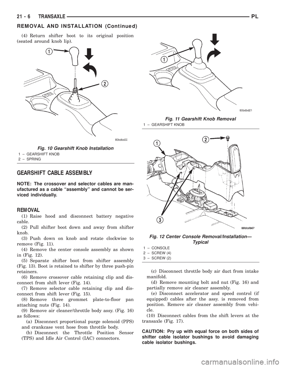
(4) Remove the center console assembly as shown
in (Fig. 12).
(5) Separate shifter boot from shifter assembly
(Fig. 13). Boot is retained to shifter by three push-pin
retainers.
(6) Remove crossover cable retaining clip and dis-
connect from shift lever (Fig. 14).
(7) Remove selector cable retaining clip and dis-
connect from shift lever (Fig. 15).
(8) Remove three grommet plate-to-floor pan
attaching nuts (Fig. 14).
(9) Remove air cleaner/throttle body assy. (Fig. 16)
as follows:
(a) Disconnect proportional purge solenoid (PPS)
and crankcase vent hose from throttle body.
(b) Disconnect the Throttle Position Sensor
(TPS) and Idle Air Control (IAC) connectors.(c) Disconnect throttle body air duct from intake
manifold.
(d) Remove mounting bolt and nut (Fig. 16) and
partially remove air cleaner assembly.
(e) Disconnect accelerator and speed control (if
equipped) cables after the assy. is removed from
position. Remove air cleaner assembly from vehi-
cle.
(10) Disconnect cables from the shift levers at the
transaxle (Fig. 17).
CAUTION: Pry up with equal force on both sides of
shifter cable isolator bushings to avoid damaging
cable isolator bushings.
Fig. 10 Gearshift Knob Installation
1 ± GEARSHIFT KNOB
2 ± SPRING
Fig. 11 Gearshift Knob Removal
1 ± GEARSHIFT KNOB
Fig. 12 Center Console Removal/InstallationÐ
Typical
1 ± CONSOLE
2 ± SCREW (4)
3 ± SCREW (2)
21 - 6 TRANSAXLEPL
REMOVAL AND INSTALLATION (Continued)
Page 920 of 1285
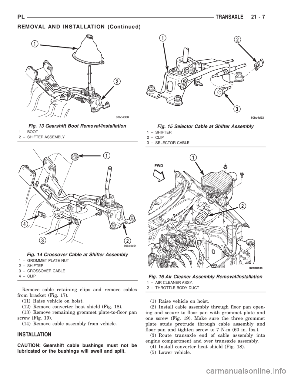
Remove cable retaining clips and remove cables
from bracket (Fig. 17).
(11) Raise vehicle on hoist.
(12) Remove converter heat shield (Fig. 18).
(13) Remove remaining grommet plate-to-floor pan
screw (Fig. 19).
(14) Remove cable assembly from vehicle.
INSTALLATION
CAUTION: Gearshift cable bushings must not be
lubricated or the bushings will swell and split.(1) Raise vehicle on hoist.
(2) Install cable assembly through floor pan open-
ing and secure to floor pan with grommet plate and
one screw (Fig. 19). Make sure the three grommet
plate studs protrude through cable assembly and
floor pan and tighten screw to 7 N´m (60 in. lbs.).
(3) Route transaxle end of cable assembly into
engine compartment and over transaxle assembly.
(4) Install converter heat shield (Fig. 18).
(5) Lower vehicle.
Fig. 13 Gearshift Boot Removal/Installation
1 ± BOOT
2 ± SHIFTER ASSEMBLY
Fig. 14 Crossover Cable at Shifter Assembly
1 ± GROMMET PLATE NUT
2 ± SHIFTER
3 ± CROSSOVER CABLE
4 ± CLIP
Fig. 15 Selector Cable at Shifter Assembly
1 ± SHIFTER
2 ± CLIP
3 ± SELECTOR CABLE
Fig. 16 Air Cleaner Assembly Removal/Installation
1 ± AIR CLEANER ASSY.
2 ± THROTTLE BODY DUCT
PLTRANSAXLE 21 - 7
REMOVAL AND INSTALLATION (Continued)
Page 921 of 1285
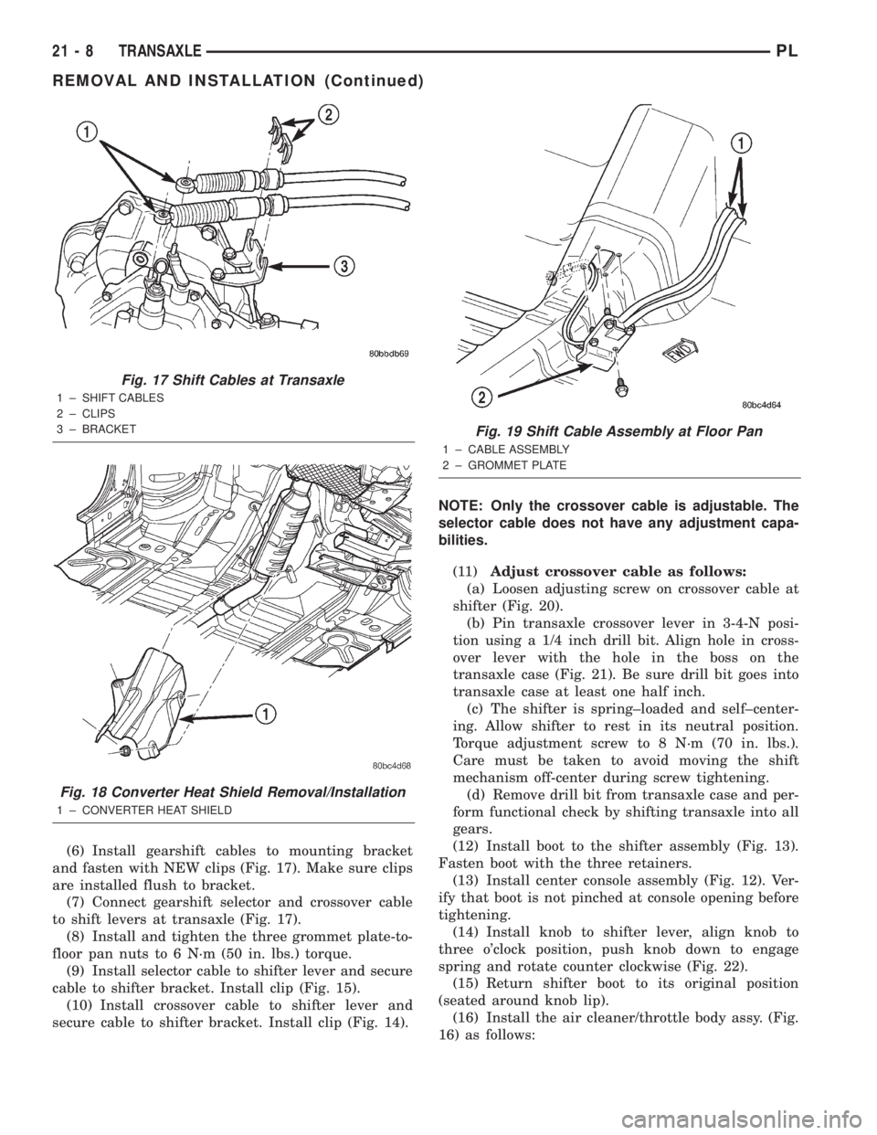
(6) Install gearshift cables to mounting bracket
and fasten with NEW clips (Fig. 17). Make sure clips
are installed flush to bracket.
(7) Connect gearshift selector and crossover cable
to shift levers at transaxle (Fig. 17).
(8) Install and tighten the three grommet plate-to-
floor pan nuts to 6 N´m (50 in. lbs.) torque.
(9) Install selector cable to shifter lever and secure
cable to shifter bracket. Install clip (Fig. 15).
(10) Install crossover cable to shifter lever and
secure cable to shifter bracket. Install clip (Fig. 14).NOTE: Only the crossover cable is adjustable. The
selector cable does not have any adjustment capa-
bilities.
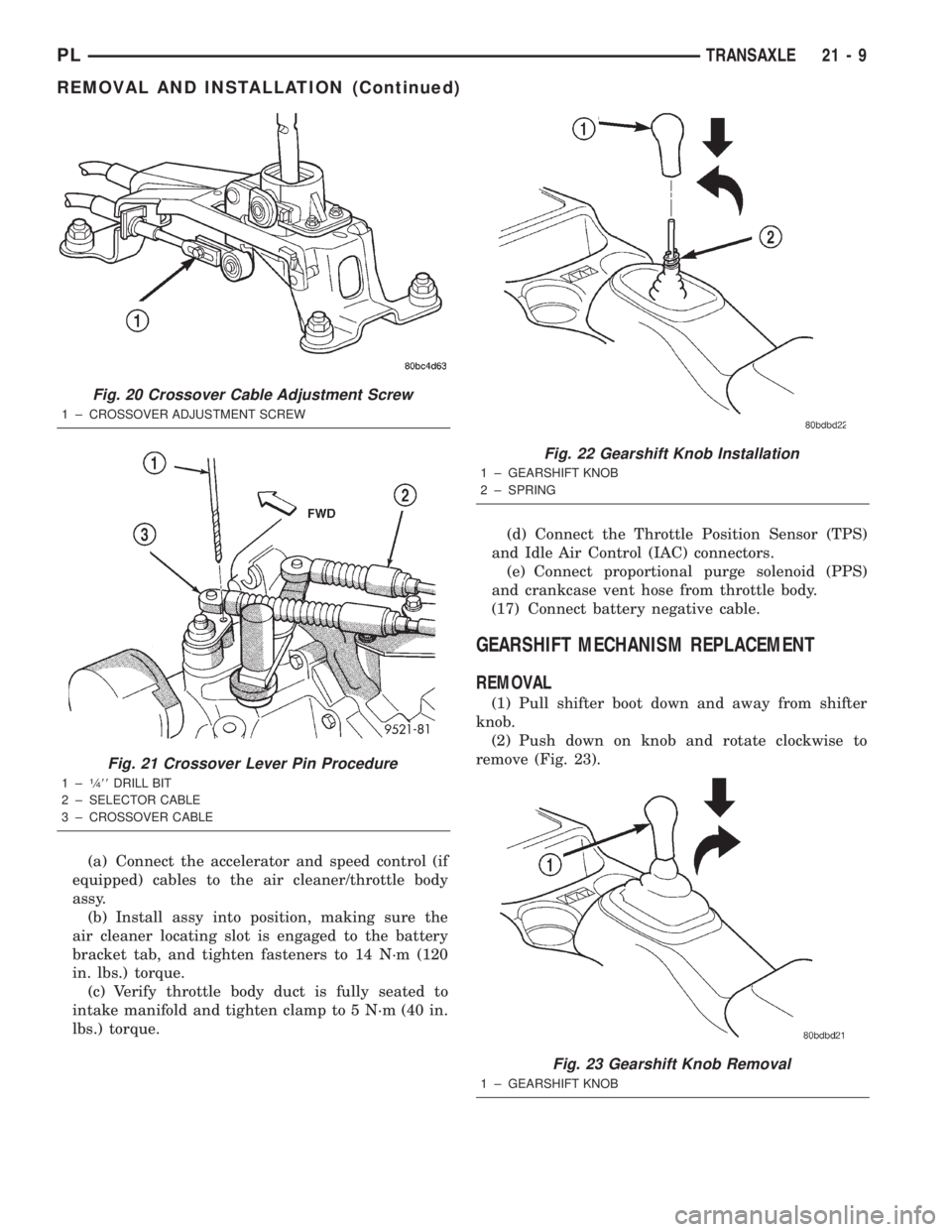
(11)Adjust crossover cable as follows:
(a) Loosen adjusting screw on crossover cable at
shifter (Fig. 20).
(b) Pin transaxle crossover lever in 3-4-N posi-
tion using a 1/4 inch drill bit. Align hole in cross-
over lever with the hole in the boss on the
transaxle case (Fig. 21). Be sure drill bit goes into
transaxle case at least one half inch.
(c) The shifter is spring±loaded and self±center-
ing. Allow shifter to rest in its neutral position.
Torque adjustment screw to 8 N´m (70 in. lbs.).
Care must be taken to avoid moving the shift
mechanism off-center during screw tightening.
(d) Remove drill bit from transaxle case and per-
form functional check by shifting transaxle into all
gears.
(12) Install boot to the shifter assembly (Fig. 13).
Fasten boot with the three retainers.
(13) Install center console assembly (Fig. 12). Ver-
ify that boot is not pinched at console opening before
tightening.
(14) Install knob to shifter lever, align knob to
three o'clock position, push knob down to engage
spring and rotate counter clockwise (Fig. 22).
(15) Return shifter boot to its original position
(seated around knob lip).
(16) Install the air cleaner/throttle body assy. (Fig.
16) as follows:
Fig. 17 Shift Cables at Transaxle
1 ± SHIFT CABLES
2 ± CLIPS
3 ± BRACKET
Fig. 18 Converter Heat Shield Removal/Installation
1 ± CONVERTER HEAT SHIELD
Fig. 19 Shift Cable Assembly at Floor Pan
1 ± CABLE ASSEMBLY
2 ± GROMMET PLATE
21 - 8 TRANSAXLEPL
REMOVAL AND INSTALLATION (Continued)
Page 922 of 1285
(a) Connect the accelerator and speed control (if
equipped) cables to the air cleaner/throttle body
assy.
(b) Install assy into position, making sure the
air cleaner locating slot is engaged to the battery
bracket tab, and tighten fasteners to 14 N´m (120
in. lbs.) torque.
(c) Verify throttle body duct is fully seated to
intake manifold and tighten clamp to 5 N´m (40 in.
lbs.) torque.(d) Connect the Throttle Position Sensor (TPS)
and Idle Air Control (IAC) connectors.
(e) Connect proportional purge solenoid (PPS)
and crankcase vent hose from throttle body.
(17) Connect battery negative cable.
GEARSHIFT MECHANISM REPLACEMENT
REMOVAL
(1) Pull shifter boot down and away from shifter
knob.
(2) Push down on knob and rotate clockwise to
remove (Fig. 23).
Fig. 20 Crossover Cable Adjustment Screw
1 ± CROSSOVER ADJUSTMENT SCREW
Fig. 21 Crossover Lever Pin Procedure
1±1¤488DRILL BIT
2 ± SELECTOR CABLE
3 ± CROSSOVER CABLE
Fig. 22 Gearshift Knob Installation
1 ± GEARSHIFT KNOB
2 ± SPRING
Fig. 23 Gearshift Knob Removal
1 ± GEARSHIFT KNOB
PLTRANSAXLE 21 - 9
REMOVAL AND INSTALLATION (Continued)
Page 923 of 1285
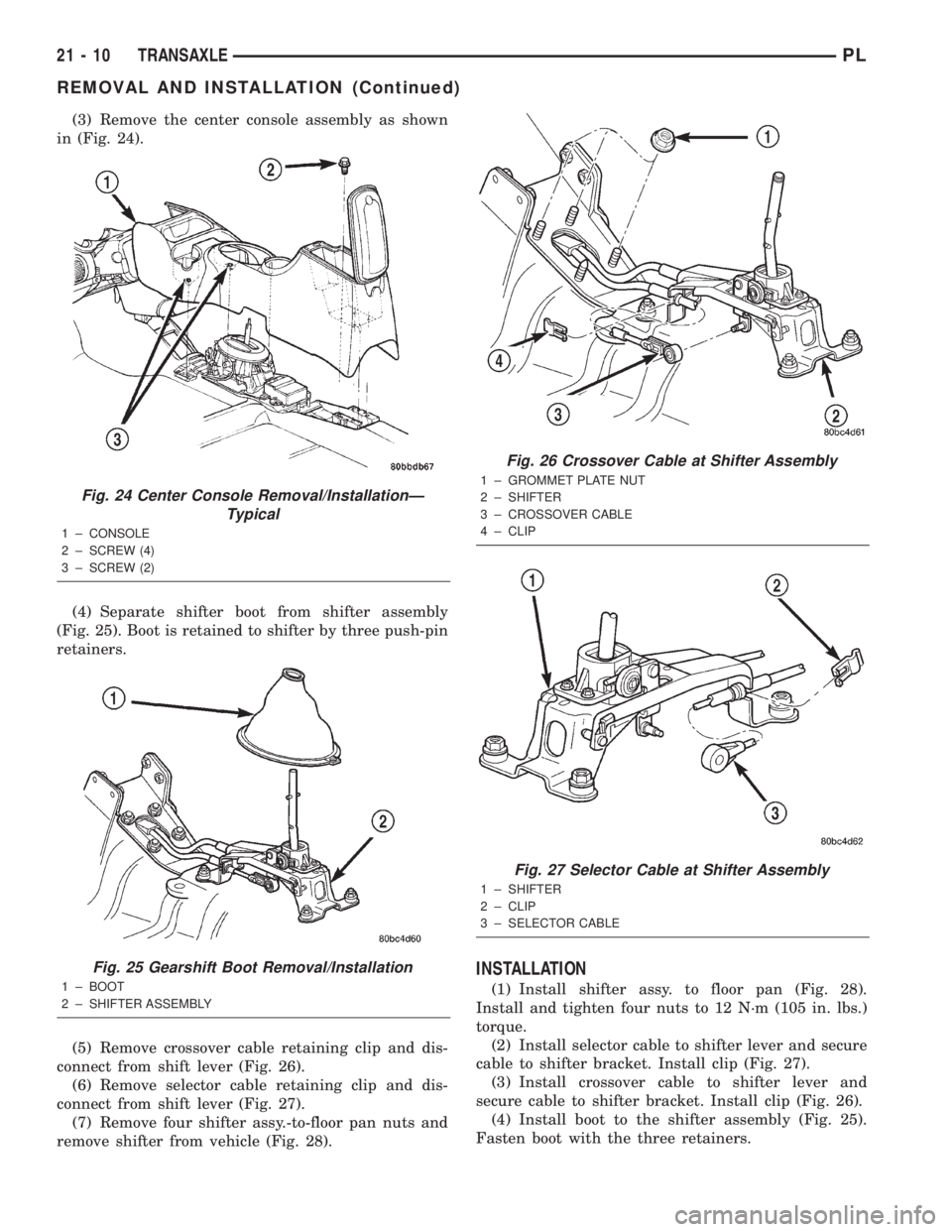
(3) Remove the center console assembly as shown
in (Fig. 24).
(4) Separate shifter boot from shifter assembly
(Fig. 25). Boot is retained to shifter by three push-pin
retainers.
(5) Remove crossover cable retaining clip and dis-
connect from shift lever (Fig. 26).
(6) Remove selector cable retaining clip and dis-
connect from shift lever (Fig. 27).
(7) Remove four shifter assy.-to-floor pan nuts and
remove shifter from vehicle (Fig. 28).
INSTALLATION
(1) Install shifter assy. to floor pan (Fig. 28).
Install and tighten four nuts to 12 N´m (105 in. lbs.)
torque.
(2) Install selector cable to shifter lever and secure
cable to shifter bracket. Install clip (Fig. 27).
(3) Install crossover cable to shifter lever and
secure cable to shifter bracket. Install clip (Fig. 26).
(4) Install boot to the shifter assembly (Fig. 25).
Fasten boot with the three retainers.
Fig. 24 Center Console Removal/InstallationÐ
Typical
1 ± CONSOLE
2 ± SCREW (4)
3 ± SCREW (2)
Fig. 25 Gearshift Boot Removal/Installation
1 ± BOOT
2 ± SHIFTER ASSEMBLY
Fig. 26 Crossover Cable at Shifter Assembly
1 ± GROMMET PLATE NUT
2 ± SHIFTER
3 ± CROSSOVER CABLE
4 ± CLIP
Fig. 27 Selector Cable at Shifter Assembly
1 ± SHIFTER
2 ± CLIP
3 ± SELECTOR CABLE
21 - 10 TRANSAXLEPL
REMOVAL AND INSTALLATION (Continued)
Page 924 of 1285
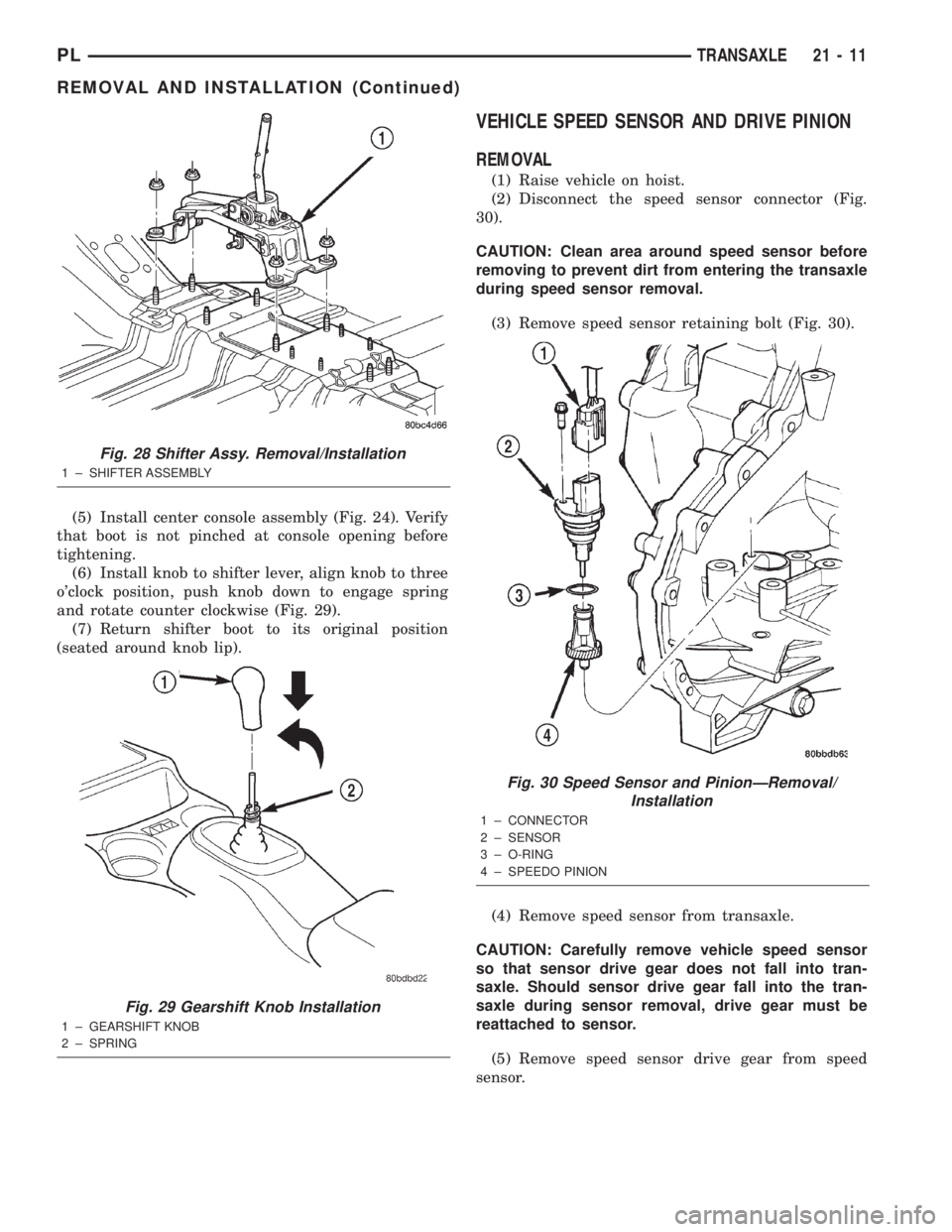
(5) Install center console assembly (Fig. 24). Verify
that boot is not pinched at console opening before
tightening.
(6) Install knob to shifter lever, align knob to three
o'clock position, push knob down to engage spring
and rotate counter clockwise (Fig. 29).
(7) Return shifter boot to its original position
(seated around knob lip).
VEHICLE SPEED SENSOR AND DRIVE PINION
REMOVAL
(1) Raise vehicle on hoist.
(2) Disconnect the speed sensor connector (Fig.
30).
CAUTION: Clean area around speed sensor before
removing to prevent dirt from entering the transaxle
during speed sensor removal.
(3) Remove speed sensor retaining bolt (Fig. 30).
(4) Remove speed sensor from transaxle.
CAUTION: Carefully remove vehicle speed sensor
so that sensor drive gear does not fall into tran-
saxle. Should sensor drive gear fall into the tran-
saxle during sensor removal, drive gear must be
reattached to sensor.
(5) Remove speed sensor drive gear from speed
sensor.
Fig. 28 Shifter Assy. Removal/Installation
1 ± SHIFTER ASSEMBLY
Fig. 29 Gearshift Knob Installation
1 ± GEARSHIFT KNOB
2 ± SPRING
Fig. 30 Speed Sensor and PinionÐRemoval/
Installation
1 ± CONNECTOR
2 ± SENSOR
3 ± O-RING
4 ± SPEEDO PINION
PLTRANSAXLE 21 - 11
REMOVAL AND INSTALLATION (Continued)
Page 962 of 1285
ADJUSTMENTS
GEARSHIFT CROSSOVER CABLE
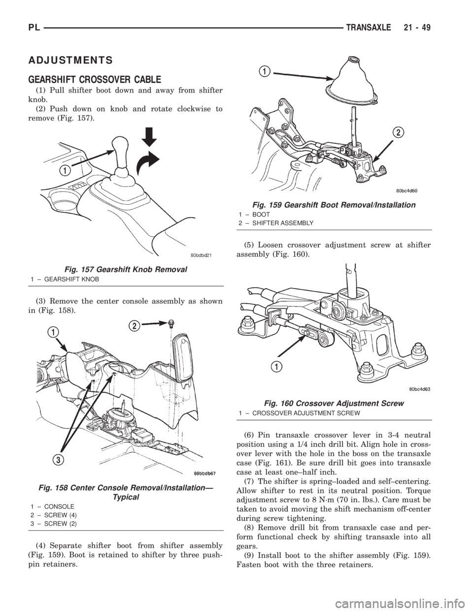
(1) Pull shifter boot down and away from shifter
knob.
(2) Push down on knob and rotate clockwise to
remove (Fig. 157).
(3) Remove the center console assembly as shown
in (Fig. 158).
(4) Separate shifter boot from shifter assembly
(Fig. 159). Boot is retained to shifter by three push-
pin retainers.(5) Loosen crossover adjustment screw at shifter
assembly (Fig. 160).
(6) Pin transaxle crossover lever in 3-4 neutral
position using a 1/4 inch drill bit. Align hole in cross-
over lever with the hole in the boss on the transaxle
case (Fig. 161). Be sure drill bit goes into transaxle
case at least one±half inch.
(7) The shifter is spring±loaded and self±centering.
Allow shifter to rest in its neutral position. Torque
adjustment screw to 8 N´m (70 in. lbs.). Care must be
taken to avoid moving the shift mechanism off-center
during screw tightening.
(8) Remove drill bit from transaxle case and per-
form functional check by shifting transaxle into all
gears.
(9) Install boot to the shifter assembly (Fig. 159).
Fasten boot with the three retainers.
Fig. 157 Gearshift Knob Removal
1 ± GEARSHIFT KNOB
Fig. 158 Center Console Removal/InstallationÐ
Typical
1 ± CONSOLE
2 ± SCREW (4)
3 ± SCREW (2)
Fig. 159 Gearshift Boot Removal/Installation
1 ± BOOT
2 ± SHIFTER ASSEMBLY
Fig. 160 Crossover Adjustment Screw
1 ± CROSSOVER ADJUSTMENT SCREW
PLTRANSAXLE 21 - 49