2000 DODGE NEON coolant capacity
[x] Cancel search: coolant capacityPage 3 of 1285
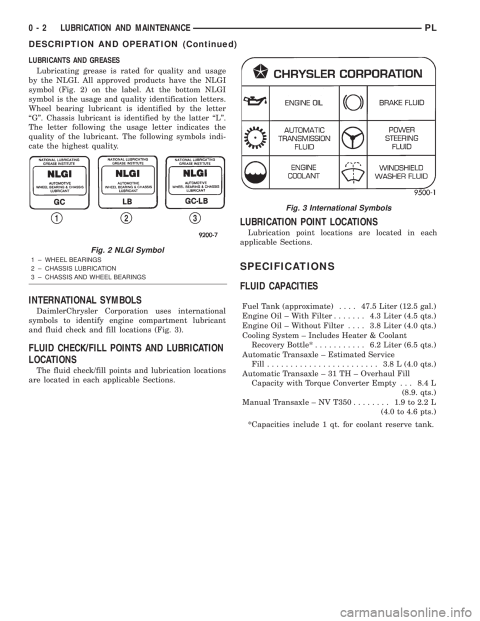
LUBRICANTS AND GREASES
Lubricating grease is rated for quality and usage
by the NLGI. All approved products have the NLGI
symbol (Fig. 2) on the label. At the bottom NLGI
symbol is the usage and quality identification letters.
Wheel bearing lubricant is identified by the letter
ªGº. Chassis lubricant is identified by the latter ªLº.
The letter following the usage letter indicates the
quality of the lubricant. The following symbols indi-
cate the highest quality.
INTERNATIONAL SYMBOLS
DaimlerChrysler Corporation uses international
symbols to identify engine compartment lubricant
and fluid check and fill locations (Fig. 3).
FLUID CHECK/FILL POINTS AND LUBRICATION
LOCATIONS
The fluid check/fill points and lubrication locations
are located in each applicable Sections.
LUBRICATION POINT LOCATIONS
Lubrication point locations are located in each
applicable Sections.
SPECIFICATIONS
FLUID CAPACITIES
Fuel Tank (approximate)....47.5 Liter (12.5 gal.)
Engine Oil ± With Filter....... 4.3Liter (4.5 qts.)
Engine Oil ± Without Filter.... 3.8Liter (4.0 qts.)
Cooling System ± Includes Heater & Coolant
Recovery Bottle*........... 6.2Liter (6.5 qts.)
Automatic Transaxle ± Estimated Service
Fill........................ 3.8L(4.0 qts.)
Automatic Transaxle ± 31 TH ± Overhaul Fill
Capacity with Torque Converter Empty . . . 8.4 L
(8.9. qts.)
Manual Transaxle ± NV T350........ 1.9to2.2L
(4.0 to 4.6 pts.)
*Capacities include 1 qt. for coolant reserve tank.
Fig. 2 NLGI Symbol
1 ± WHEEL BEARINGS
2 ± CHASSIS LUBRICATION
3 ± CHASSIS AND WHEEL BEARINGS
Fig. 3 International Symbols
0 - 2 LUBRICATION AND MAINTENANCEPL
DESCRIPTION AND OPERATION (Continued)
Page 180 of 1285
COOLING SYSTEM
TABLE OF CONTENTS
page page
DESCRIPTION AND OPERATION
COOLING SYSTEM........................1
COOLANT...............................2
COOLANT PERFORMANCE..................2
COOLANT RECOVERY SYSTEM..............3
ENGINE THERMOSTAT.....................3
RADIATOR..............................3
RADIATOR COOLING FAN MODULE...........3
COOLING SYSTEM PRESSURE CAP..........4
RADIATOR HOSES AND CLAMPS............5
WATER PUMP...........................5
AUTOMATIC TRANSMISSION OIL COOLER.....6
ACCESSORY DRIVE BELTS.................6
ENGINE BLOCK HEATER...................6
DIAGNOSIS AND TESTING
COOLING SYSTEM DIAGNOSIS..............7
ENGINE THERMOSTAT TESTING............14
ACCESSORY DRIVE BELT DIAGNOSIS........14
WATER PUMP DIAGNOSIS................15
COOLING SYSTEM FLOW CHECK...........15
ELECTRIC FAN MOTOR TEST...............15
COOLANT CONCENTRATION TESTING........15
TESTING COOLING SYSTEM FOR LEAKS.....15
PRESSURE CAP TO FILLER NECK SEAL
PRESSURE RELIEF CHECK...............16
PRESSURE TESTING COOLING SYSTEM
PRESSURE CAP.......................16
LOW COOLANT LEVEL AERATION...........17
DEAERATION...........................17
TEMPERATURE GAUGE INDICATION.........17
ENGINE BLOCK HEATER..................17
SERVICE PROCEDURES
COOLANT LEVEL CHECKÐROUTINE.........17COOLANTÐADDING ADDITIONAL...........18
COOLANT LEVELÐSERVICING.............18
COOLING SYSTEMÐDRAINING.............19
COOLING SYSTEMÐREFILLING............19
REMOVAL AND INSTALLATION
WATER PUMP..........................19
WATER PUMP INLET TUBE................20
ENGINE THERMOSTAT....................20
RADIATOR.............................21
RADIATOR DRAINCOCK...................22
COOLING FAN MODULE...................22
COOLANT RECOVERY CONTAINER..........23
ENGINE BLOCK HEATER..................24
ACCESSORY DRIVE BELTS................24
AUTOMATIC BELT TENSIONER & PULLEY....26
DISASSEMBLY AND ASSEMBLY
COOLING FAN MODULE...................26
CLEANING AND INSPECTION
WATER PUMP..........................28
ACCESSORY DRIVE BELT INSPECTION.......28
COOLING SYSTEM CAP...................28
COOLING SYSTEM CLEANING..............28
RADIATOR FLUSHING....................28
REVERSE FLUSHING.....................29
CHEMICAL CLEANING....................29
ADJUSTMENTS
BELT TENSION..........................29
SPECIFICATIONS
COOLING SYSTEM CAPACITY..............30
TORQUE SPECIFICATIONS.................30
SPECIAL TOOLS
COOLING..............................30
DESCRIPTION AND OPERATION
COOLING SYSTEM
The cooling system consists of an engine cooling
module, thermostat, coolant, and a water pump to
circulate the coolant. The engine cooling module may
consist of a radiator, electric fan motor, fan, shroud,
coolant reserve system, transmission oil cooler, hoses,clamps, air conditioning condenser and transmission
oil lines.
²When the Engine is cold: The thermostat is
closed and the cooling system has no flow through
the radiator. The coolant flows through the engine,
heater system and bypass.
²When the Engine is warm: Thermostat is open
and the cooling system has flow through the radiator,
engine, heater system, and bypass.
PLCOOLING SYSTEM 7 - 1
Page 209 of 1285
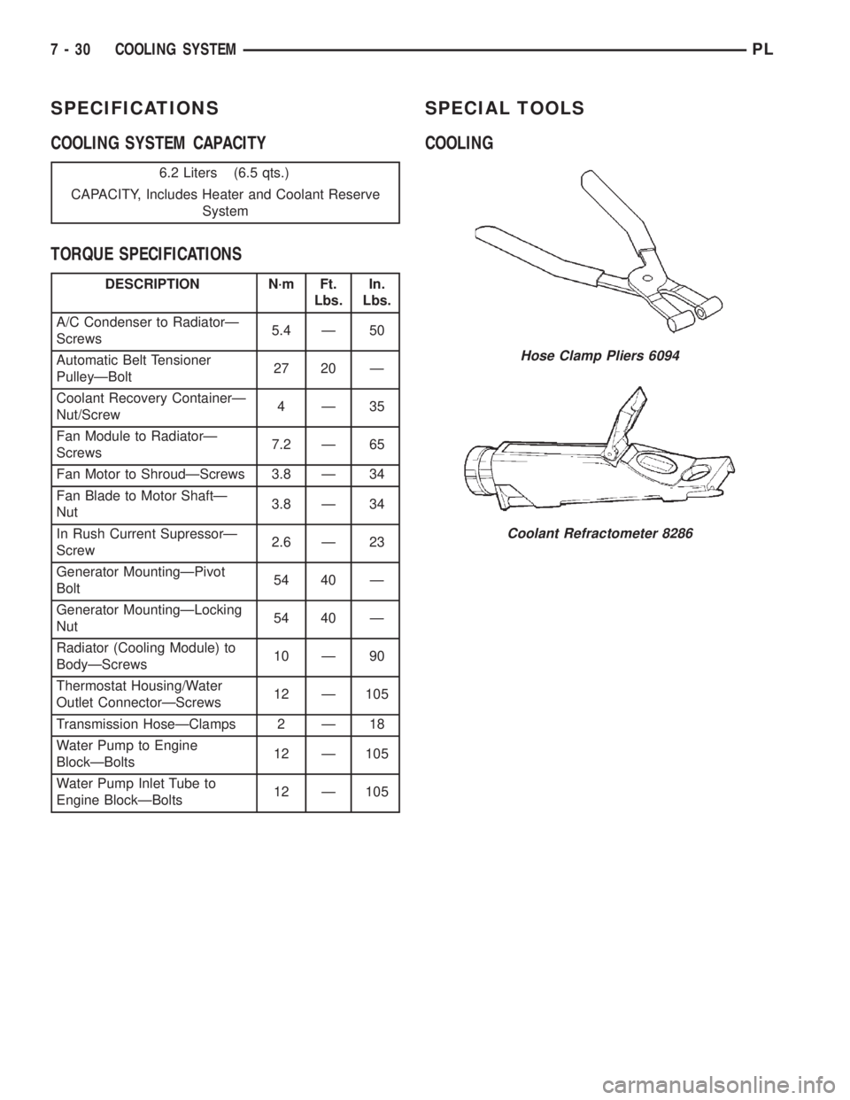
SPECIFICATIONS
COOLING SYSTEM CAPACITY
TORQUE SPECIFICATIONSSPECIAL TOOLS
COOLING
6.2 Liters (6.5 qts.)
CAPACITY, Includes Heater and Coolant Reserve
System
DESCRIPTION N´m Ft.
Lbs.In.
Lbs.
A/C Condenser to RadiatorÐ
Screws5.4 Ð 50
Automatic Belt Tensioner
PulleyÐBolt27 20 Ð
Coolant Recovery ContainerÐ
Nut/Screw4Ð35
Fan Module to RadiatorÐ
Screws7.2 Ð 65
Fan Motor to ShroudÐScrews 3.8 Ð 34
Fan Blade to Motor ShaftÐ
Nut3.8 Ð 34
In Rush Current SupressorÐ
Screw2.6 Ð 23
Generator MountingÐPivot
Bolt54 40 Ð
Generator MountingÐLocking
Nut54 40 Ð
Radiator (Cooling Module) to
BodyÐScrews10 Ð 90
Thermostat Housing/Water
Outlet ConnectorÐScrews12 Ð 105
Transmission HoseÐClamps 2 Ð 18
Water Pump to Engine
BlockÐBolts12 Ð 105
Water Pump Inlet Tube to
Engine BlockÐBolts12 Ð 105
Hose Clamp Pliers 6094
Coolant Refractometer 8286
7 - 30 COOLING SYSTEMPL
Page 220 of 1285
(4) Remove the thermowrap from vehicle.
INSTALLATION
For installation, reverse the above procedures.
BATTERY TRAY
REMOVAL
(1) Remove battery. Refer to Battery Removal and
Installation in this section.
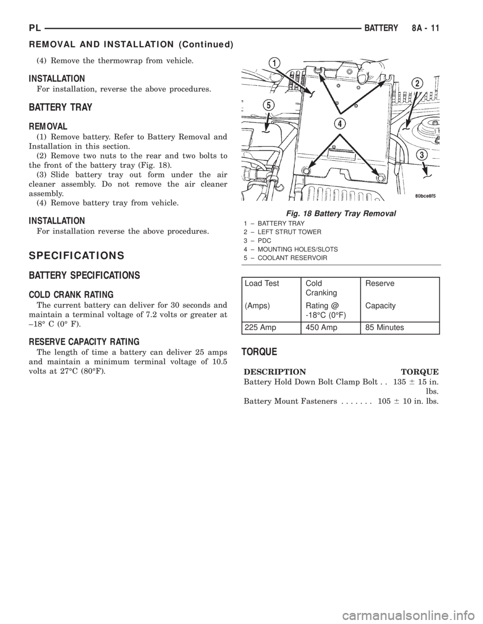
(2) Remove two nuts to the rear and two bolts to
the front of the battery tray (Fig. 18).
(3) Slide battery tray out form under the air
cleaner assembly. Do not remove the air cleaner
assembly.
(4) Remove battery tray from vehicle.
INSTALLATION
For installation reverse the above procedures.
SPECIFICATIONS
BATTERY SPECIFICATIONS
COLD CRANK RATING
The current battery can deliver for 30 seconds and
maintain a terminal voltage of 7.2 volts or greater at
±18É C (0É F).
RESERVE CAPACITY RATING
The length of time a battery can deliver 25 amps
and maintain a minimum terminal voltage of 10.5
volts at 27ÉC (80ÉF).TORQUE
DESCRIPTION TORQUE
Battery Hold Down Bolt Clamp Bolt . . 135615 in.
lbs.
Battery Mount Fasteners....... 105610 in. lbs.
Fig. 18 Battery Tray Removal
1 ± BATTERY TRAY
2 ± LEFT STRUT TOWER
3 ± PDC
4 ± MOUNTING HOLES/SLOTS
5 ± COOLANT RESERVOIR
Load Test Cold
CrankingReserve
(Amps) Rating @
-18ÉC (0ÉF)Capacity
225 Amp 450 Amp 85 Minutes
PLBATTERY 8A - 11
REMOVAL AND INSTALLATION (Continued)
Page 852 of 1285
OPERATION
The combination coolant temperature sensor has
two elements. One element supplies coolant temper-
ature signal to the PCM. The other element supplies
coolant temperature signal to the instrument panel
gauge cluster. The PCM determines engine coolant
temperature from the coolant temperature sensor.
As coolant temperature varies the coolant temper-
ature sensors resistance changes resulting in a differ-
ent input voltage to the PCM and the instrument
panel gauge cluster.When the engine is cold, the PCM will provide
slightly richer air- fuel mixtures and higher idle
speeds until normal operating temperatures are
reached.
The PCM has a dual temperature range program
for better sensor accuracy at cold temperatures. At
key-ON the PCM sends a regulated five volt signal
through a 10,000 ohm resistor to the sensor. When
the sensed voltage reaches approximately 1.25 volts
the PCM turns on the transistor. The transistor con-
nects a 1,000 ohm resistor in parallel with the 10,000
ohm resistor. With this drop in resistance the PCM
recognizes an increase in voltage on the input circuit.
FUEL LEVEL SENSORÐPCM INPUT
DESCRIPTION
The fuel gauge level sending unit is attached to the
fuel pump module.
OPERATION
The fuel level sensor (fuel gauge sending unit)
sends a signal to the PCM to indicate fuel level. The
purpose of this feature is to prevent a false setting of
misfire and fuel system monitor trouble codes if the
fuel level is less than approximately 15 percent of its
rated capacity. It is also used to send a signal for fuel
gauge operation via the PCI bus circuits.
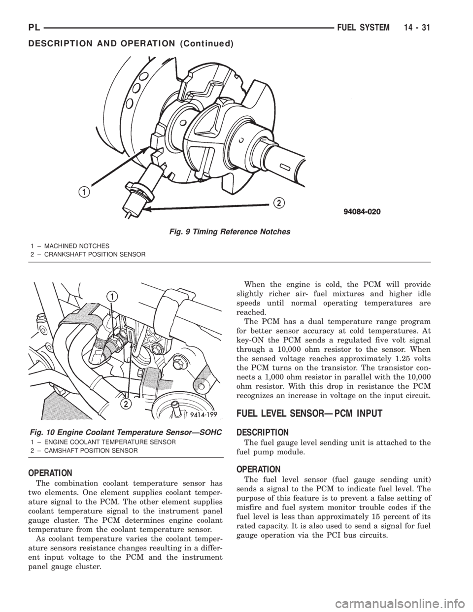
Fig. 9 Timing Reference Notches
1 ± MACHINED NOTCHES
2 ± CRANKSHAFT POSITION SENSOR
Fig. 10 Engine Coolant Temperature SensorÐSOHC
1 ± ENGINE COOLANT TEMPERATURE SENSOR
2 ± CAMSHAFT POSITION SENSOR
PLFUEL SYSTEM 14 - 31
DESCRIPTION AND OPERATION (Continued)
Page 1104 of 1285
The PCM is programmed to maintain the optimum
air/fuel ratio of 14.7 to 1. This is done by making
short term corrections in the fuel injector pulse width
based on the O2S output. The programmed memory
acts as a self calibration tool that the engine control-
ler uses to compensate for variations in engine spec-
ifications, sensor tolerances and engine fatigue over
the life span of the engine. By monitoring the actual
air-fuel ratio with the O2S (short term) and multiply-
ing that with the program long-term (adaptive) mem-
ory and comparing that to the limit, it can be
determined whether it will pass an emissions test. If
a malfunction occurs such that the PCM cannot
maintain the optimum A/F ratio, then the MIL will
be illuminated.
Monitor OperationÐFuel systems monitors do
not have a pre-test because they are continuously
running monitors. Therefore, the PCM constantly
monitors Short Term Compensation and Long Term
Adaptive memory.
Lean: If at anytime during a lean engine operation,
short term compensation multiplied by long term
adaptive exceeds a certain percentage for an
extended period, the PCM sets a Fuel System Lean
Fault for that trip and a Freeze Frame is entered.
Rich: If at anytime during a rich operation, Short
Term Compensation multiplied by Long Term Adap-
tive is less than a predetermined value, the PCM
checks the Purge Free Cells.
Purge Free Cells are values placed in Adaptive
Memory cells when the EVAP Purge Solenoid is OFF.
Two, three or four Purge Free cells are used. One cor-
responds to an Adaptive Memory cell at idle, the
other to a cell that is off-idle. For example, if a Purge
Free cell is labeled PFC1, it would hold the value for
Adaptive Memory cell C1 under non-purge condi-
tions.
If all Purge Free Cells are less than a certain per-
centage, and the Adaptive Memory factor is less than
a certain percentage, the PCM sets a Fuel System
Rich fault for that trip and a Freeze Frame is
entered.
The Fuel Monitor is a two trip monitor. The PCM
records engine data in Freeze Frame upon setting of
the first fault, or maturing code. When the fuel mon-
itor fails on a second consecutive trip, the code is
matured and the MIL is illuminated. The stored
Freeze Frame data is still from the first fault.
In order for the PCM to extinguish the MIL, the
Fuel Monitor must pass in a Similar Condition Win-
dow. The similar conditions relate to RPM and load.
The engine must be within a predetermined percent-
age of both RPM and load when the monitor runs to
count a good trip. As with all DTCs, three good tripsare required to extinguish the MIL and 40 warm up
cycles are required to erase the DTC. If the engine
does not run in a Similar Conditions Window, the
Task Manager extinguishes the MIL after 80 good
trips.
Enabling ConditionsÐThe following conditions
must be met to operate the fuel control monitor:
²PCM not in fuel crank mode (engine running)
²PCM in Closed Loop fuel control
²Fuel system updating Long Term Adaptive
²Fuel level above 15% of capacity
²Fuel level below 85% of capacity
Pending ConditionsÐThe Fuel Control Monitor
does not operate if the MIL is illuminated for any of
the following:
²Misfire Monitor
²Upstream O2S
²EVAP Purge Solenoid Electrical PCM Self Test
Fault
²Camshaft or Crankshaft Position Sensor
²Fuel Injectors
²Ignition Coil Primary
²Throttle Position (TPS) Sensor
²Engine Coolant Temperature (ECT) Sensor
²Manifold Absolute Pressure (MAP) Sensor
²Idle Air Control (IAC)
²5V Output Too Low
²EGR Monitor
²EGR Solenoid Circuit
²Vehicle Speed Sensor
²Oxygen Sensor Monitor
²Oxygen Sensor Heater Monitor
²Oxygen Sensor Electrical
²Idle Speed Rationality
²Intake Air Temperature
SuspendÐThe Task Manager will suspend
maturing a Fuel System fault if any of the following
are present:
²Oxygen Sensor Response, Priority 1
²O2 Heater, Priority 1
²Misfire Monitor, Priority 2
EVAPORATIVE EMISSIONS MONITOR
LEAK DETECTION PUMP MONITORÐThe
leak detection assembly incorporates two primary
functions: it must detect a leak in the evaporative
system and seal the evaporative system so the leak
detection test can be run.
The primary components within the assembly are:
A three port solenoid that activates both of the func-
tions listed above; a pump which contains a switch,
two check valves and a spring/diaphragm, a canister
vent valve (CVV) seal which contains a spring loaded
vent seal valve.
PLEMISSION CONTROL SYSTEMS 25 - 17
DESCRIPTION AND OPERATION (Continued)
Page 1109 of 1285
Pending ConditionsÐThere are not conditions
or situations that prompt conflict or suspension of
testing. The oxygen sensor heater test is not run
pending resolution of MIL illumination due to oxygen
sensor failure.
SuspendÐThere are no conditions which exist for
suspending the Heater Monitor.
CATALYST MONITOR
To comply with clean air regulations, vehicles are
equipped with catalytic converters. These converters
reduce the emission of hydrocarbons, oxides of nitro-
gen and carbon monoxide.
Normal vehicle miles or engine misfire can cause a
catalyst to decay. A meltdown of the ceramic core can
cause a reduction of the exhaust passage. This can
increase vehicle emissions and deteriorate engine
performance, driveability and fuel economy.
The catalyst monitor uses dual oxygen sensors
(O2S's) to monitor the efficiency of the converter. The
dual O2S strategy is based on the fact that as a cat-
alyst deteriorates, its oxygen storage capacity and its
efficiency are both reduced. By monitoring the oxy-
gen storage capacity of a catalyst, its efficiency can
be indirectly calculated. The upstream O2S is used to
detect the amount of oxygen in the exhaust gas
before the gas enters the catalytic converter. The
PCM calculates the A/F mixture from the output of
the O2S. A low voltage indicates high oxygen content
(lean mixture). A high voltage indicates a low content
of oxygen (rich mixture).
When the upstream O2S detects a lean condition,
there is an abundance of oxygen in the exhaust gas.
A functioning converter would store this oxygen so it
can use it for the oxidation of HC and CO. As the
converter absorbs the oxygen, there will be a lack of
oxygen downstream of the converter. The output of
the downstream O2S will indicate limited activity in
this condition.
As the converter loses the ability to store oxygen,
the condition can be detected from the behavior of
the downstream O2S. When the efficiency drops, no
chemical reaction takes place. This means the con-
centration of oxygen will be the same downstream as
upstream. The output voltage of the downstream
O2S copies the voltage of the upstream sensor. The
only difference is a time lag (seen by the PCM)
between the switching of the O2S's.
To monitor the system, the number of lean-to-rich
switches of upstream and downstream O2S's is
counted. The ratio of downstream switches to
upstream switches is used to determine whether the
catalyst is operating properly. An effective catalyst
will have fewer downstream switches than it has
upstream switches i.e., a ratio closer to zero. For atotally ineffective catalyst, this ratio will be one-to-
one, indicating that no oxidation occurs in the device.
The system must be monitored so that when cata-
lyst efficiency deteriorates and exhaust emissions
increase to over the legal limit, the MIL (check
engine lamp) will be illuminated.
Monitor OperationÐTo monitor catalyst effi-
ciency, the PCM expands the rich and lean switch
points of the heated oxygen sensor. With extended
switch points, the air/fuel mixture runs richer and
leaner to overburden the catalytic converter. Once
the test is started, the air/fuel mixture runs rich and
lean and the O2 switches are counted. A switch is
counted when an oxygen sensor signal goes from
below the lean threshold to above the rich threshold.
The number of Rear O2 sensor switches is divided by
the number of Front O2 sensor switches to determine
the switching ratio.
The test runs for 20 seconds. As catalyst efficiency
deteriorated over the life of the vehicle, the switch
rate at the downstream sensor approaches that of the
upstream sensor. If at any point during the test
period the switch ratio reaches a predetermined
value, a counter is incremented by one. The monitor
is enabled to run another test during that trip. When
the test fails three times, the counter increments to
three, a malfunction is entered, and a Freeze Frame
is stored. When the counter increments to three dur-
ing the next trip, the code is matured and the MIL is
illuminated. If the test passes the first, no further
testing is conducted during that trip.
The MIL is extinguished after three consecutive
good trips. The good trip criteria for the catalyst
monitor is more stringent than the failure criteria. In
order to pass the test and increment one good trip,
the downstream sensor switch rate must be less than
80% of the upstream rate (60% for manual transmis-
sions). The failure percentages are 90% and 70%
respectively.
Enabling ConditionsÐThe following conditions
must typically be met before the PCM runs the cat-
alyst monitor. Specific times for each parameter may
be different from engine to engine.
²Accumulated drive time
²Enable time
²Ambient air temperature
²Barometric pressure
²Catalyst warm-up counter
²Engine coolant temperature
²Accumulated throttle position sensor
²Vehicle speed
²MAP
²RPM
²Engine in closed loop
²Fuel level
25 - 22 EMISSION CONTROL SYSTEMSPL
DESCRIPTION AND OPERATION (Continued)