2000 DODGE NEON vacuum check valve
[x] Cancel search: vacuum check valvePage 81 of 1285
DESCRIPTION AND OPERATION
BASE BRAKE SYSTEM OPERATION
When a vehicle needs to be stopped, the driver
applies the brake pedal. The brake pedal pushes the
input rod of the power brake booster into the booster.
The booster uses vacuum to ease pedal effort as force
is transferred through the booster to the master cyl-
inder. The booster's output rod pushes in the master
cylinder's primary and secondary pistons applying
hydraulic pressure through the chassis brake tubes
and proportioning valves (rear only) to the brakes at
each tire and wheel assembly.
Front disc brakes control the braking of the front
wheels; rear braking is controlled by rear drum
brakes as standard equipment. Rear disc brakes and
an antilock brake system (ABS) with traction control
are optional.
The hydraulic brake system is diagonally split on
both the non-antilock and antilock braking systems.
This means the left front and right rear brakes are
on one hydraulic circuit and the right front and left
rear are on the other.
Vehicles equipped with the optional antilock brake
system (ABS) use a system designated Mark 20e.
This system shares most base brake hardware used
on vehicles without ABS. A vehicle equipped with
ABS, however, uses a different master cylinder and
brake tubes. Also included in the ABS system is an
integrated control unit (ICU) and four wheel speed
sensors. These components are described in detail in
the ANTILOCK BRAKE SYSTEM section in this
group of the service manual. All vehicles with ABS
come standard with four-wheel-disc brakes and trac-
tion control.
The parking brakes are hand-operated. When
applied, the parking brake lever pulls on cables that
actuate brake shoes at each rear wheel. The parking
brake lever has an automatic adjusting feature that
takes up any excessive slack in the parking brake
cable system.
BASE BRAKE SYSTEM COMPONENTS
BRAKE PEDAL
A suspended-type brake pedal is used on this vehi-
cle. The pedal pivots on a shaft mounted in the pedal
support bracket under the instrument panel. The
pedal connects to the power brake booster input rod
and pushes it in when the pedal is applied.
The brake pedal and it's pad are serviceable sepa-
rately.
POWER BRAKE BOOSTER
There are two different power brake booster
designs, although externally they appear the same.
All vehicles use a 205 mm tandem diaphragm power
brake booster. The two boosters are internally tuned
differently depending on whether the vehicle is
equipped with the standard front disc/rear drum
brake combination or the optional front disc/rear disc
(four-wheel disc) brake combination. If the power
brake booster requires replacement, be sure it is
replaced with the correct part.
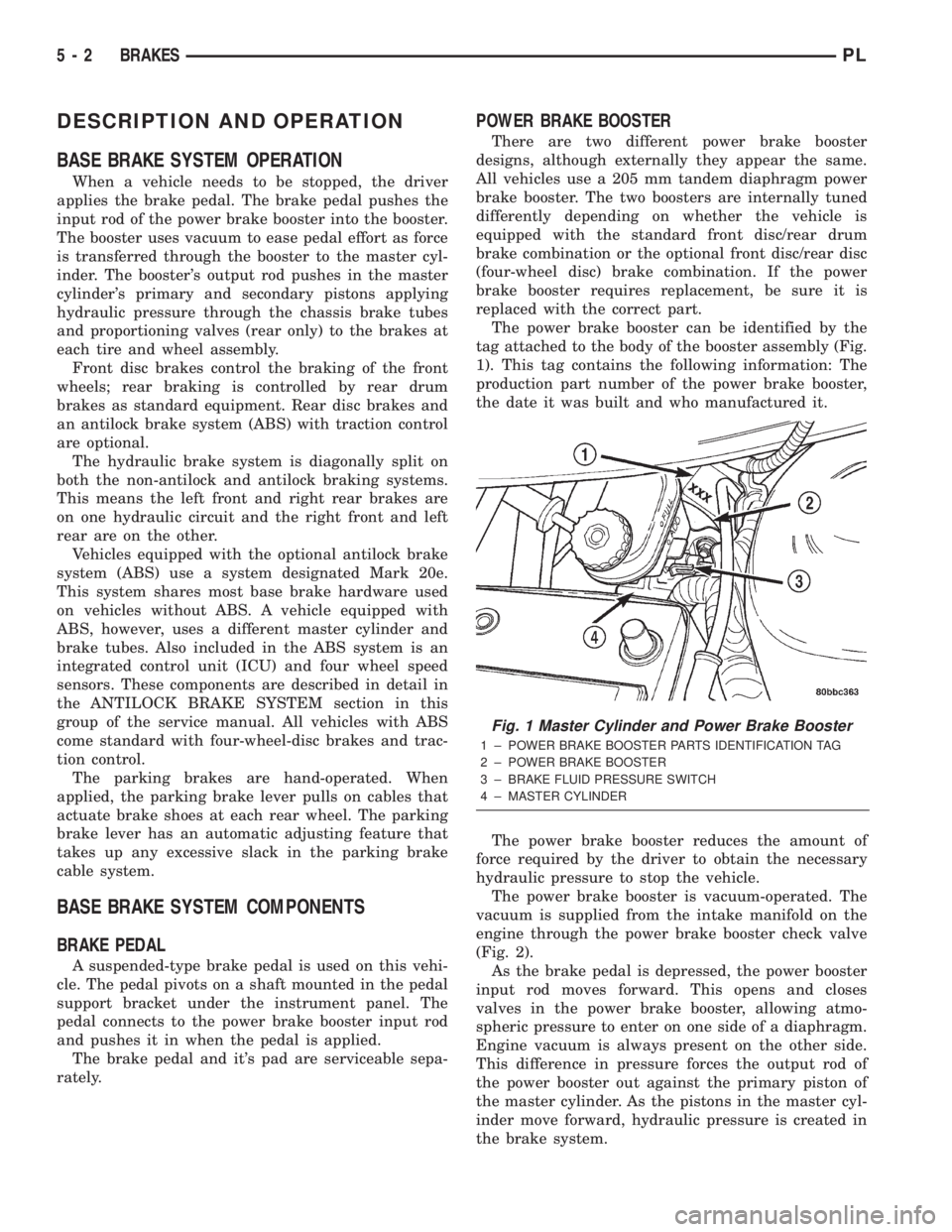
The power brake booster can be identified by the
tag attached to the body of the booster assembly (Fig.
1). This tag contains the following information: The
production part number of the power brake booster,
the date it was built and who manufactured it.
The power brake booster reduces the amount of
force required by the driver to obtain the necessary
hydraulic pressure to stop the vehicle.
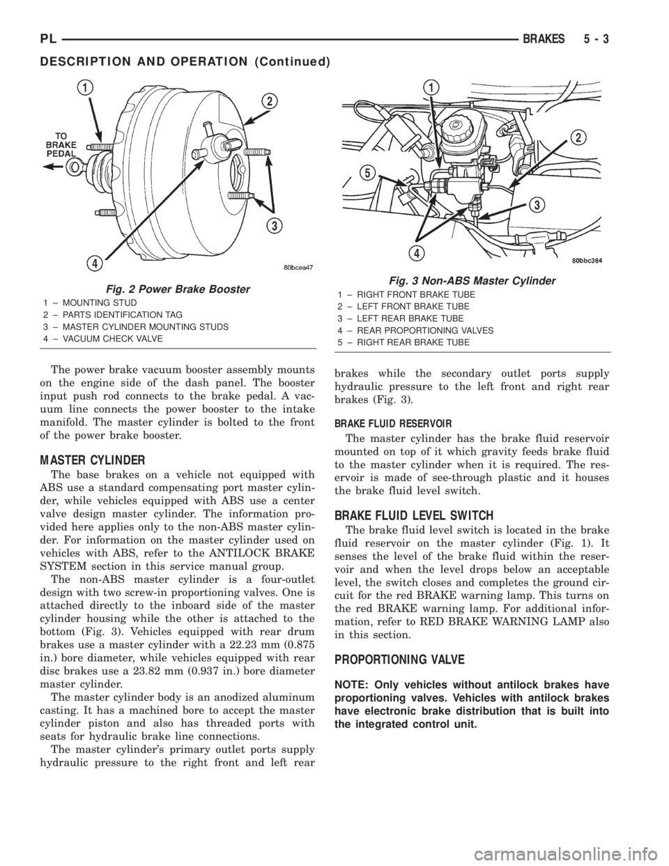
The power brake booster is vacuum-operated. The
vacuum is supplied from the intake manifold on the
engine through the power brake booster check valve
(Fig. 2).
As the brake pedal is depressed, the power booster
input rod moves forward. This opens and closes
valves in the power brake booster, allowing atmo-
spheric pressure to enter on one side of a diaphragm.
Engine vacuum is always present on the other side.
This difference in pressure forces the output rod of
the power booster out against the primary piston of
the master cylinder. As the pistons in the master cyl-
inder move forward, hydraulic pressure is created in
the brake system.
Fig. 1 Master Cylinder and Power Brake Booster
1 ± POWER BRAKE BOOSTER PARTS IDENTIFICATION TAG
2 ± POWER BRAKE BOOSTER
3 ± BRAKE FLUID PRESSURE SWITCH
4 ± MASTER CYLINDER
5 - 2 BRAKESPL
Page 82 of 1285
The power brake vacuum booster assembly mounts
on the engine side of the dash panel. The booster
input push rod connects to the brake pedal. A vac-
uum line connects the power booster to the intake
manifold. The master cylinder is bolted to the front
of the power brake booster.
MASTER CYLINDER
The base brakes on a vehicle not equipped with
ABS use a standard compensating port master cylin-
der, while vehicles equipped with ABS use a center
valve design master cylinder. The information pro-
vided here applies only to the non-ABS master cylin-
der. For information on the master cylinder used on
vehicles with ABS, refer to the ANTILOCK BRAKE
SYSTEM section in this service manual group.
The non-ABS master cylinder is a four-outlet
design with two screw-in proportioning valves. One is
attached directly to the inboard side of the master
cylinder housing while the other is attached to the
bottom (Fig. 3). Vehicles equipped with rear drum
brakes use a master cylinder with a 22.23 mm (0.875
in.) bore diameter, while vehicles equipped with rear
disc brakes use a 23.82 mm (0.937 in.) bore diameter
master cylinder.
The master cylinder body is an anodized aluminum
casting. It has a machined bore to accept the master
cylinder piston and also has threaded ports with
seats for hydraulic brake line connections.
The master cylinder's primary outlet ports supply
hydraulic pressure to the right front and left rearbrakes while the secondary outlet ports supply
hydraulic pressure to the left front and right rear
brakes (Fig. 3).
BRAKE FLUID RESERVOIR
The master cylinder has the brake fluid reservoir
mounted on top of it which gravity feeds brake fluid
to the master cylinder when it is required. The res-
ervoir is made of see-through plastic and it houses
the brake fluid level switch.
BRAKE FLUID LEVEL SWITCH
The brake fluid level switch is located in the brake
fluid reservoir on the master cylinder (Fig. 1). It
senses the level of the brake fluid within the reser-
voir and when the level drops below an acceptable
level, the switch closes and completes the ground cir-
cuit for the red BRAKE warning lamp. This turns on
the red BRAKE warning lamp. For additional infor-
mation, refer to RED BRAKE WARNING LAMP also
in this section.
PROPORTIONING VALVE
NOTE: Only vehicles without antilock brakes have
proportioning valves. Vehicles with antilock brakes
have electronic brake distribution that is built into
the integrated control unit.
Fig. 2 Power Brake Booster
1 ± MOUNTING STUD
2 ± PARTS IDENTIFICATION TAG
3 ± MASTER CYLINDER MOUNTING STUDS
4 ± VACUUM CHECK VALVE
Fig. 3 Non-ABS Master Cylinder
1 ± RIGHT FRONT BRAKE TUBE
2 ± LEFT FRONT BRAKE TUBE
3 ± LEFT REAR BRAKE TUBE
4 ± REAR PROPORTIONING VALVES
5 ± RIGHT REAR BRAKE TUBE
PLBRAKES 5 - 3
DESCRIPTION AND OPERATION (Continued)
Page 90 of 1285
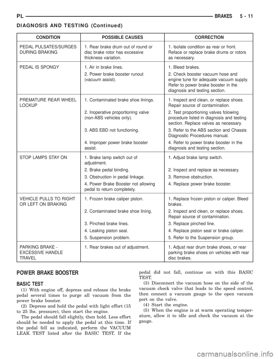
CONDITION POSSIBLE CAUSES CORRECTION
PEDAL PULSATES/SURGES
DURING BRAKING1. Rear brake drum out of round or
disc brake rotor has excessive
thickness variation.1. Isolate condition as rear or front.
Reface or replace brake drums or rotors
as necessary.
PEDAL IS SPONGY 1. Air in brake lines. 1. Bleed brakes.
2. Power brake booster runout
(vacuum assist).2. Check booster vacuum hose and
engine tune for adequate vacuum supply.
Refer to power brake booster in the
diagnosis and testing section.
PREMATURE REAR WHEEL
LOCKUP1. Contaminated brake shoe linings. 1. Inspect and clean, or replace shoes.
Repair source of contamination.
2. Inoperative proportioning valve
(non-ABS vehicles only).2. Test proportioning valves folowing
procedure listed in diagnosis and testing
section. Replace valves as necessary.
3. ABS EBD not functioning. 3. Refer to the ABS section and Chassis
Diagnostic Procedures manual.
4. Improper power brake booster
assist.4. Refer to power brake booster in the
diagnosis and testing section.
STOP LAMPS STAY ON 1. Brake lamp switch out of
adjustment.1. Adjust brake lamp switch.
2. Brake pedal binding. 2. Inspect and replace as necessary.
3. Obstruction in pedal linkage. 3. Remove obstruction.
4. Power Brake Booster not allowing
pedal to return completely.4. Replace power brake booster.
VEHICLE PULLS TO RIGHT
OR LEFT ON BRAKING1. Frozen brake caliper piston. 1. Replace frozen piston or caliper. Bleed
brakes.
2. Contaminated brake shoe lining. 2. Inspect and clean, or replace shoes.
Repair source of contamination.
3. Pinched brake lines. 3. Replace pinched line.
4. Leaking piston seal. 4. Replace piston seal or brake caliper.
5. Suspension problem. 5. Refer to the Suspension group.
PARKING BRAKE -
EXCESSIVE HANDLE
TRAVEL1. Rear brakes out of adjustment. 1. Adjust rear drum brake shoes, or rear
parking brake shoes on vehicles with rear
disc brakes.
POWER BRAKE BOOSTER
BASIC TEST
(1) With engine off, depress and release the brake
pedal several times to purge all vacuum from the
power brake booster.
(2) Depress and hold the pedal with light effort (15
to 25 lbs. pressure), then start the engine.
The pedal should fall slightly, then hold. Less effort
should be needed to apply the pedal at this time. If
the pedal fell as indicated, perform the VACUUM
LEAK TEST listed after the BASIC TEST. If thepedal did not fall, continue on with this BASIC
TEST.
(3) Disconnect the vacuum hose on the side of the
vacuum check valve that leads to the speed control,
then connect a vacuum gauge to the open vacuum
port on the valve.
(4) Start the engine.
(5) When the engine is at warm operating temper-
ature, allow it to idle and check the vacuum at the
gauge.
PLBRAKES 5 - 11
DIAGNOSIS AND TESTING (Continued)
Page 91 of 1285
If the vacuum supply is 12 inches Hg (40.5 kPa) or
more, the power brake booster is defective and must
be replaced. If the vacuum supply is below 12 inches,
continue on with this BASIC TEST.
(6) Shut off the engine.
(7) Connect the vacuum gauge to the vacuum ref-
erence port on the engine intake manifold.
(8)
Start the engine and observe the vacuum gauge.
If the vacuum is still low, check the engine tune
and repair as necessary. If the vacuum is above 12
inches, the hose or check to the booster has a restric-
tion or leak.
Once an adequate vacuum supply is obtained,
repeat the BASIC TEST.
VACUUM LEAK TEST
(1) Disconnect the vacuum hose on the side of the
power brake booster vacuum check valve that leads
to the speed control, then connect a vacuum gauge to
the open vacuum port on the valve.
(2) Remove the remaining hose on the vacuum
check valve that is not the vacuum supply hose com-
ing from the intake manifold. Cap off the open port
on the check valve.
(3) Start the engine.
(4) Allow the engine to warm up to normal operat-
ing temperature and engine idle.
(5) Using vacuum line pliers, close off the vacuum
supply hose near the booster and observe the vacuum
gauge.
If the vacuum drop exceeds 1.0 inch Hg (3.3 kPa)
in one minute, repeat the above steps to confirm the
reading. The vacuum loss should be less than 1.0
inch Hg in one minute time span. If the loss is more
than 1.0 inch Hg, replace the power brake booster. If
it is not, continue on with this test.
(6) Remove the pliers from the hose temporarily.
(7) Apply light effort (approximately 15 lbs. of
force) to the brake pedal and hold the pedal steady.
Do not move the pedal once the pressure is applied
or the test results may vary.
(8) Have an assistant reattach the pliers to the
vacuum supply hose.
(9) Allow 5 seconds for stabilization, then observe
the vacuum gauge.
If the vacuum drop exceeds 3.0 inches Hg (10 kPa)
in 15 seconds, repeat the above steps to confirm the
reading. The vacuum loss should be less than 3.0
inches Hg in 15 seconds time span. If the loss is
more than 3.0 inches Hg, replace the power brake
booster. If it is not, the booster is not defective.
DRUM BRAKE AUTOMATIC ADJUSTER
To properly test the drum brake automatic
adjuster, the aide of a helper inside the vehicle to
apply the brakes will be necessary.(1) Raise the vehicle. Refer to HOISTING in the
LUBRICATION AND MAINTENANCE group for the
proper lifting procedure.
(2) Remove the access plug from the rear adjust-
ment slot in each brake support plate.
(3) Insert a thin screwdriver in the adjustment
slot and push back the adjustment lever. With the
lever in this position, back the star wheel adjustment
off approximately 10 notches. This will eliminate the
possibility that the brake is at full adjustment, and
can be adjusted no further.
(4)
Remove the screwdriver from the adjustment slot.
(5) Watch the star wheel through the adjustment
slot, while a helper applies the brake pedal. As the
brake shoes apply, the adjustment lever should move
downward, turning the star wheel. A definite rotation
of the adjuster star wheel can be observed if the
automatic adjuster is working properly.
If the star wheel does not move as indicated, the
brake drum needs to be removed and further inspec-
tion of the rear brakes is necessary.
(6) If the star wheel is operating properly, readjust
the brakes. Refer to ADJUSTMENTS in this section
of this service manual group.
(7) Reinstall the adjustment slot access plug.
(8) Lower the vehicle.
BRAKE ROTOR
Any servicing of the rotor requires extreme care to
maintain the rotor within service tolerances to
ensure proper brake action.
Excessive runout or wobble in a rotor can increase
pedal travel due to piston knock-back. This increases
guide pin sleeve wear due to the tendency of the cal-
iper to follow the rotor wobble.
When diagnosing a brake noise or pulsation, the
machined disc braking surface should be checked and
inspected.
BRAKING SURFACE INSPECTION
Light braking surface scoring and wear is accept-
able. If heavy scoring or warping is evident, the rotor
must be refaced or replaced. Refer to SERVICE PRO-
CEDURES in this section of this group for informa-
tion on brake rotor machining.
Excessive wear and scoring of the rotor can cause
improper lining contact on the rotor's braking sur-
face. If the ridges on the rotor are not removed before
new brake shoes are installed, improper wear of the
shoes will result.
If a vehicle has not been driven for a period of
time, the rotor's braking surface will rust in the
areas not covered by the brake shoes at that time.
Once the vehicle is driven, noise and chatter from
the disc brakes can result when the brakes are
applied.
5 - 12 BRAKESPL
DIAGNOSIS AND TESTING (Continued)
Page 107 of 1285
(4) Gently pull back on the brake pedal until the
pedal stops moving. This will ratchet the switch
plunger backward to the correct adjustment position.
(5) Check the stop lamps to verify they are operat-
ing properly and not staying on when the pedal is in
the released position.
MASTER CYLINDER
NOTE: Before proceeding with this procedure,
review SERVICE WARNINGS AND CAUTIONS at the
beginning of REMOVAL AND INSTALLATION in this
section.
REMOVAL
CAUTION: The vacuum in the power brake booster
must be pumped down before removing the master
cylinder to prevent the booster from sucking in any
contamination. This can be done by pumping the
brake pedal while the engine is not running until a
firm brake pedal is achieved.
(1) With the engine not running, pump the brake
pedal 4-5 strokes until the pedal feel is firm.
(2) Disconnect the negative (ground) cable from
the battery and isolate the cable.
(3) Disconnect the positive cable from the battery,
then remove the battery from the battery tray. There
is one nut securing the clamp on the backside of the
battery holding it in place.
(4) Remove the vehicle wiring harness connector
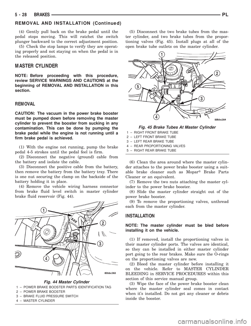
from brake fluid level switch in master cylinder
brake fluid reservoir (Fig. 44).(5) Disconnect the two brake tubes from the mas-
ter cylinder, and two brake tubes from the propor-
tioning valves (Fig. 45). Install plugs at all of the
open brake tube outlets on the master cylinder.
(6) Clean the area around where the master cylin-
der attaches to the power brake booster using a suit-
able brake cleaner such as MopartBrake Parts
Cleaner or an equivalent.
(7) Remove the two nuts attaching the master cyl-
inder to the power brake booster.
(8) Slide the master cylinder straight out of the
power brake booster.
(9) To remove the proportioning valves, unthread
each from the master cylinder.
INSTALLATION
NOTE: The master cylinder must be bled before
installing it on the vehicle.
(1) If removed, install the proportioning valves in
their master cylinder ports. The valves are identical,
so they can be installed in either master cylinder
port going to the rear brakes. Make sure the O-rings
on the proportioning valves are new.
(2) Bleed the master cylinder before installing it
on the vehicle. Refer to MASTER CYLINDER
BLEEDING in SERVICE PROCEDURES within this
section of this service manual group.
(3) Wipe the face of the power brake booster clean
where the master cylinder seal comes in contact
when it's installed. Do not get any cleaner or debris
inside the booster.
Fig. 44 Master Cylinder
1 ± POWER BRAKE BOOSTER PARTS IDENTIFICATION TAG
2 ± POWER BRAKE BOOSTER
3 ± BRAKE FLUID PRESSURE SWITCH
4 ± MASTER CYLINDER
Fig. 45 Brake Tubes At Master Cylinder
1 ± RIGHT FRONT BRAKE TUBE
2 ± LEFT FRONT BRAKE TUBE
3 ± LEFT REAR BRAKE TUBE
4 ± REAR PROPORTIONING VALVES
5 ± RIGHT REAR BRAKE TUBE
5 - 28 BRAKESPL
REMOVAL AND INSTALLATION (Continued)
Page 109 of 1285
(4) Fill the reservoir with fresh clean DOT 3 brake
fluid. Refer to BRAKE FLUID LEVEL CHECKING
in the SERVICE PROCEDURES section in this sec-
tion of this service manual group.
BRAKE FLUID LEVEL SWITCH
NOTE: Before proceeding with this procedure,
review SERVICE WARNINGS AND CAUTIONS at the
beginning of REMOVAL AND INSTALLATION in this
section.
REMOVAL
(1) Remove the vehicle wiring harness connector
from brake fluid level switch in master cylinder
brake fluid reservoir (Fig. 44).
(2) Push together the retaining tabs holding the
brake fluid level switch in place in the brake fluid
reservoir (Fig. 46).
(3) Pull the brake fluid level switch out the other
side of the reservoir.
INSTALLATION
(1) Align the brake fluid level switch with its
mounting hole on the left side of the master cylinder
brake fluid reservoir. Push the switch into the fluid
reservoir until the switch retaining tabs are
expanded on the other side of the reservoir, locking it
in place (Fig. 46).
(2) Connect the brake fluid level switch wiring
connector (Fig. 44).
POWER BRAKE BOOSTER
NOTE: Before proceeding with this procedure,
review SERVICE WARNINGS AND CAUTIONS at the
beginning of REMOVAL AND INSTALLATION in this
section.
REMOVAL
(1) Disconnect negative (ground) cable from the
battery and isolate the cable.
(2) Disconnect the positive cable from the battery,
then remove the battery from the battery tray. There
is one nut securing the clamp on the backside of the
battery holding it in place.
(3) Remove the one nut and one bolt securing the
air cleaner box in place, then disconnect the wiring
harness connector at the air inlet sensor.
(4) Lift the air cleaner box upward enough to clear
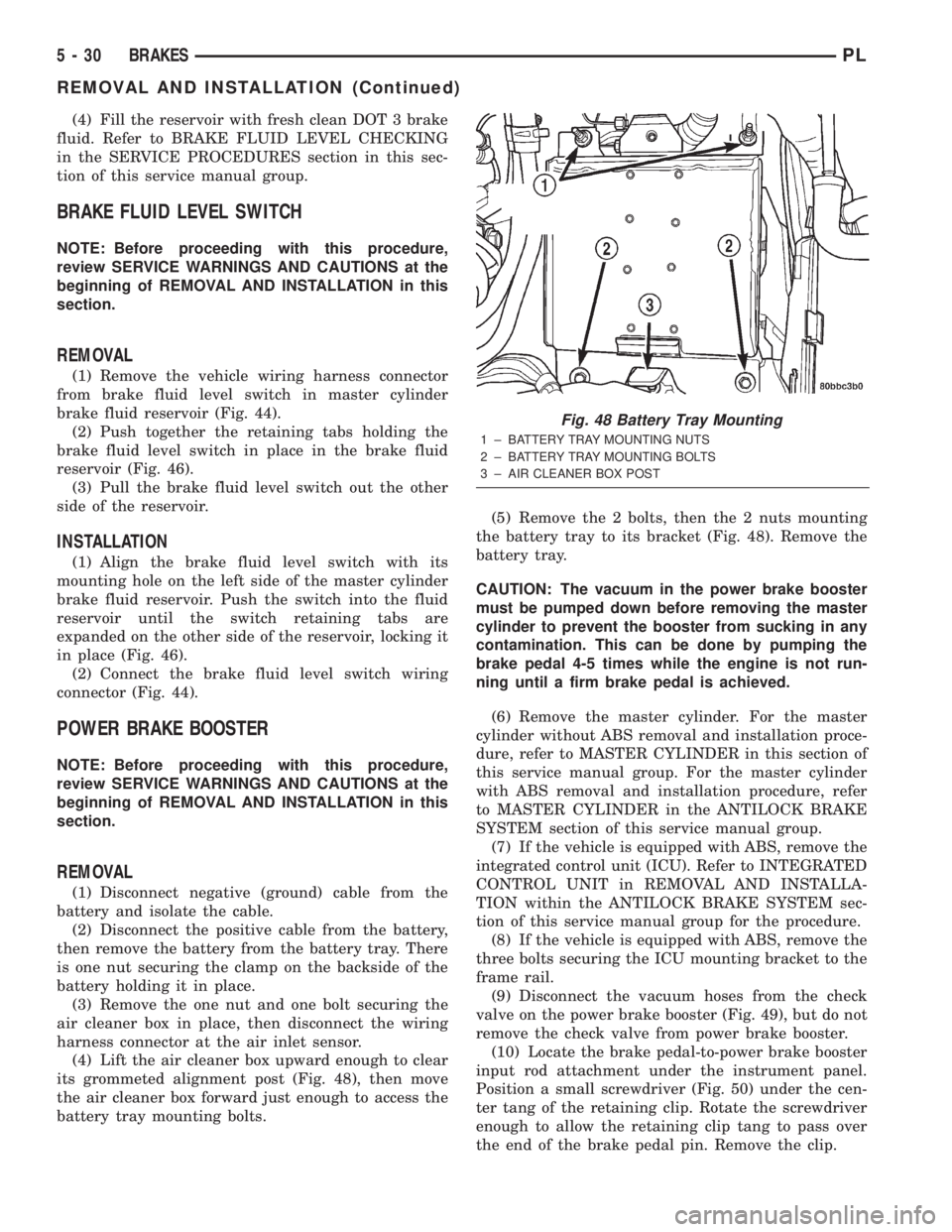
its grommeted alignment post (Fig. 48), then move
the air cleaner box forward just enough to access the
battery tray mounting bolts.(5) Remove the 2 bolts, then the 2 nuts mounting
the battery tray to its bracket (Fig. 48). Remove the
battery tray.
CAUTION: The vacuum in the power brake booster
must be pumped down before removing the master
cylinder to prevent the booster from sucking in any
contamination. This can be done by pumping the
brake pedal 4-5 times while the engine is not run-
ning until a firm brake pedal is achieved.
(6) Remove the master cylinder. For the master
cylinder without ABS removal and installation proce-
dure, refer to MASTER CYLINDER in this section of
this service manual group. For the master cylinder
with ABS removal and installation procedure, refer
to MASTER CYLINDER in the ANTILOCK BRAKE
SYSTEM section of this service manual group.
(7) If the vehicle is equipped with ABS, remove the
integrated control unit (ICU). Refer to INTEGRATED
CONTROL UNIT in REMOVAL AND INSTALLA-
TION within the ANTILOCK BRAKE SYSTEM sec-
tion of this service manual group for the procedure.
(8) If the vehicle is equipped with ABS, remove the
three bolts securing the ICU mounting bracket to the
frame rail.
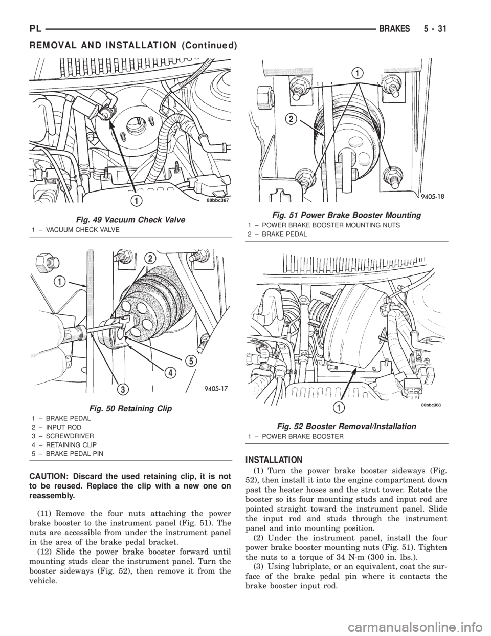
(9) Disconnect the vacuum hoses from the check
valve on the power brake booster (Fig. 49), but do not
remove the check valve from power brake booster.
(10) Locate the brake pedal-to-power brake booster
input rod attachment under the instrument panel.
Position a small screwdriver (Fig. 50) under the cen-
ter tang of the retaining clip. Rotate the screwdriver
enough to allow the retaining clip tang to pass over
the end of the brake pedal pin. Remove the clip.
Fig. 48 Battery Tray Mounting
1 ± BATTERY TRAY MOUNTING NUTS
2 ± BATTERY TRAY MOUNTING BOLTS
3 ± AIR CLEANER BOX POST
5 - 30 BRAKESPL
REMOVAL AND INSTALLATION (Continued)
Page 110 of 1285
CAUTION: Discard the used retaining clip, it is not
to be reused. Replace the clip with a new one on
reassembly.
(11) Remove the four nuts attaching the power
brake booster to the instrument panel (Fig. 51). The
nuts are accessible from under the instrument panel
in the area of the brake pedal bracket.
(12) Slide the power brake booster forward until
mounting studs clear the instrument panel. Turn the
booster sideways (Fig. 52), then remove it from the
vehicle.
INSTALLATION
(1) Turn the power brake booster sideways (Fig.
52), then install it into the engine compartment down
past the heater hoses and the strut tower. Rotate the
booster so its four mounting studs and input rod are
pointed straight toward the instrument panel. Slide
the input rod and studs through the instrument
panel and into mounting position.
(2) Under the instrument panel, install the four
power brake booster mounting nuts (Fig. 51). Tighten
the nuts to a torque of 34 N´m (300 in. lbs.).
(3) Using lubriplate, or an equivalent, coat the sur-
face of the brake pedal pin where it contacts the
brake booster input rod.
Fig. 49 Vacuum Check Valve
1 ± VACUUM CHECK VALVE
Fig. 50 Retaining Clip
1 ± BRAKE PEDAL
2 ± INPUT ROD
3 ± SCREWDRIVER
4 ± RETAINING CLIP
5 ± BRAKE PEDAL PIN
Fig. 51 Power Brake Booster Mounting
1 ± POWER BRAKE BOOSTER MOUNTING NUTS
2 ± BRAKE PEDAL
Fig. 52 Booster Removal/Installation
1 ± POWER BRAKE BOOSTER
PLBRAKES 5 - 31
REMOVAL AND INSTALLATION (Continued)
Page 111 of 1285
CAUTION: Use only a new brake booster input rod-
to-brake pedal retaining clip to ensure proper
retainment.
(4) Connect the power brake booster input rod-to-
brake pedal pin. Install a new retaining clip. Do not
use the old clip.
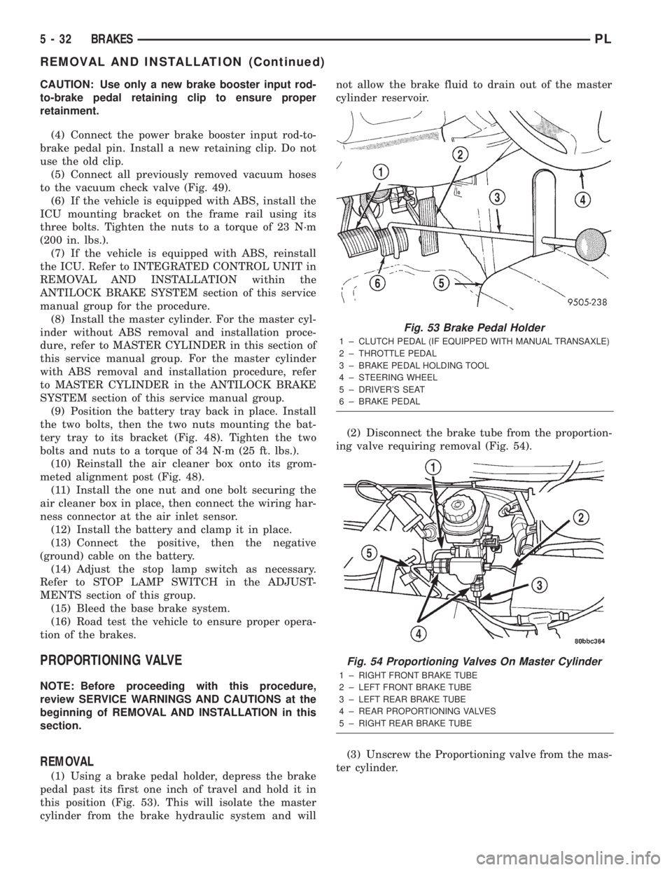
(5) Connect all previously removed vacuum hoses
to the vacuum check valve (Fig. 49).
(6) If the vehicle is equipped with ABS, install the
ICU mounting bracket on the frame rail using its
three bolts. Tighten the nuts to a torque of 23 N´m
(200 in. lbs.).
(7) If the vehicle is equipped with ABS, reinstall
the ICU. Refer to INTEGRATED CONTROL UNIT in
REMOVAL AND INSTALLATION within the
ANTILOCK BRAKE SYSTEM section of this service
manual group for the procedure.
(8) Install the master cylinder. For the master cyl-
inder without ABS removal and installation proce-
dure, refer to MASTER CYLINDER in this section of
this service manual group. For the master cylinder
with ABS removal and installation procedure, refer
to MASTER CYLINDER in the ANTILOCK BRAKE
SYSTEM section of this service manual group.
(9) Position the battery tray back in place. Install
the two bolts, then the two nuts mounting the bat-
tery tray to its bracket (Fig. 48). Tighten the two
bolts and nuts to a torque of 34 N´m (25 ft. lbs.).
(10) Reinstall the air cleaner box onto its grom-
meted alignment post (Fig. 48).
(11) Install the one nut and one bolt securing the
air cleaner box in place, then connect the wiring har-
ness connector at the air inlet sensor.
(12) Install the battery and clamp it in place.
(13) Connect the positive, then the negative
(ground) cable on the battery.
(14) Adjust the stop lamp switch as necessary.
Refer to STOP LAMP SWITCH in the ADJUST-
MENTS section of this group.
(15) Bleed the base brake system.
(16) Road test the vehicle to ensure proper opera-
tion of the brakes.
PROPORTIONING VALVE
NOTE: Before proceeding with this procedure,
review SERVICE WARNINGS AND CAUTIONS at the
beginning of REMOVAL AND INSTALLATION in this
section.
REMOVAL
(1) Using a brake pedal holder, depress the brake
pedal past its first one inch of travel and hold it in
this position (Fig. 53). This will isolate the master
cylinder from the brake hydraulic system and willnot allow the brake fluid to drain out of the master
cylinder reservoir.
(2) Disconnect the brake tube from the proportion-
ing valve requiring removal (Fig. 54).
(3) Unscrew the Proportioning valve from the mas-
ter cylinder.
Fig. 53 Brake Pedal Holder
1 ± CLUTCH PEDAL (IF EQUIPPED WITH MANUAL TRANSAXLE)
2 ± THROTTLE PEDAL
3 ± BRAKE PEDAL HOLDING TOOL
4 ± STEERING WHEEL
5 ± DRIVER'S SEAT
6 ± BRAKE PEDAL
Fig. 54 Proportioning Valves On Master Cylinder
1 ± RIGHT FRONT BRAKE TUBE
2 ± LEFT FRONT BRAKE TUBE
3 ± LEFT REAR BRAKE TUBE
4 ± REAR PROPORTIONING VALVES
5 ± RIGHT REAR BRAKE TUBE
5 - 32 BRAKESPL
REMOVAL AND INSTALLATION (Continued)