2000 DODGE NEON power steering fluid
[x] Cancel search: power steering fluidPage 4 of 1285
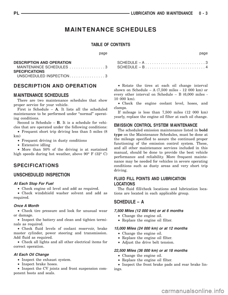
MAINTENANCE SCHEDULES
TABLE OF CONTENTS
page page
DESCRIPTION AND OPERATION
MAINTENANCE SCHEDULES................3
SPECIFICATIONS
UNSCHEDULED INSPECTION................3SCHEDULE ± A...........................3
SCHEDULE ± B...........................4
DESCRIPTION AND OPERATION
MAINTENANCE SCHEDULES
There are two maintenance schedules that show
proper service for your vehicle.
First is Schedule ±A. It lists all the scheduled
maintenance to be performed under ªnormalº operat-
ing conditions.
Second is Schedule ±B. It is a schedule for vehi-
cles that are operated under the following conditions:
²Frequent short trip driving less than 5 miles (8
km)
²Frequent driving in dusty conditions
²Extensive idling
²More than 50% of the driving is at sustained
high speeds during hot weather, above 90É F (32É C)
SPECIFICATIONS
UNSCHEDULED INSPECTION
At Each Stop For Fuel
²Check engine oil level and add as required.
²Check windshield washer solvent and add as
required.
Once A Month
²Check tire pressure and look for unusual wear
or damage.
²Inspect the battery and clean and tighten termi-
nals as required.
²Check fluid levels of coolant reservoir, brake
master cylinder, power steering and transmission.
Add fluid as required.
²Check all lights and all other electrical items for
correct operation.
At Each Oil Change
²Inspect the exhaust system.
²Inspect brake hoses.
²Inspect the CV joints and front suspension com-
ponent boots and seals.²Rotate the tires at each oil change interval
shown on Schedule ± A (7,500 miles - 12 000 km) or
every other interval on Schedule ± B (6,000 miles -
10 000 km).
²Check the engine coolant level, hoses, and
clamps.
If mileage is less than 7,500 miles (12 000 km)
yearly, replace the engine oil filter at each oil change.
EMISSION CONTROL SYSTEM MAINTENANCE
The scheduled emission maintenance listed inbold
typeon the Maintenance Schedules, must be done at
the mileage specified to assure the continued proper
functioning of the emission control system. These,
and all other maintenance services included in this
manual, should be done to provide the best vehicle
performance and reliability. More frequent mainte-
nance may be needed for vehicles in severe operating
conditions such as dusty areas and very short trip
driving.
FLUID FILL POINTS AND LUBRICATION
LOCATIONS
The fluid fill/check locations and lubrication loca-
tions are located in each applicable group.
SCHEDULE ± A
7,500 Miles (12 000 km) or at 6 months
²Change the engine oil.
²Replace the engine oil filter.
15,000 Miles (24 000 km) or at 12 months
²Change the engine oil.
²Replace the engine oil filter.
²Adjust the drive belt tension.
22,500 Miles (36 000 km) or at 18 months
²Change the engine oil.
²Replace the engine oil filter.
²Inspect the front brake pads and rear brake lin-
ings.
PLLUBRICATION AND MAINTENANCE 0 - 3
Page 15 of 1285
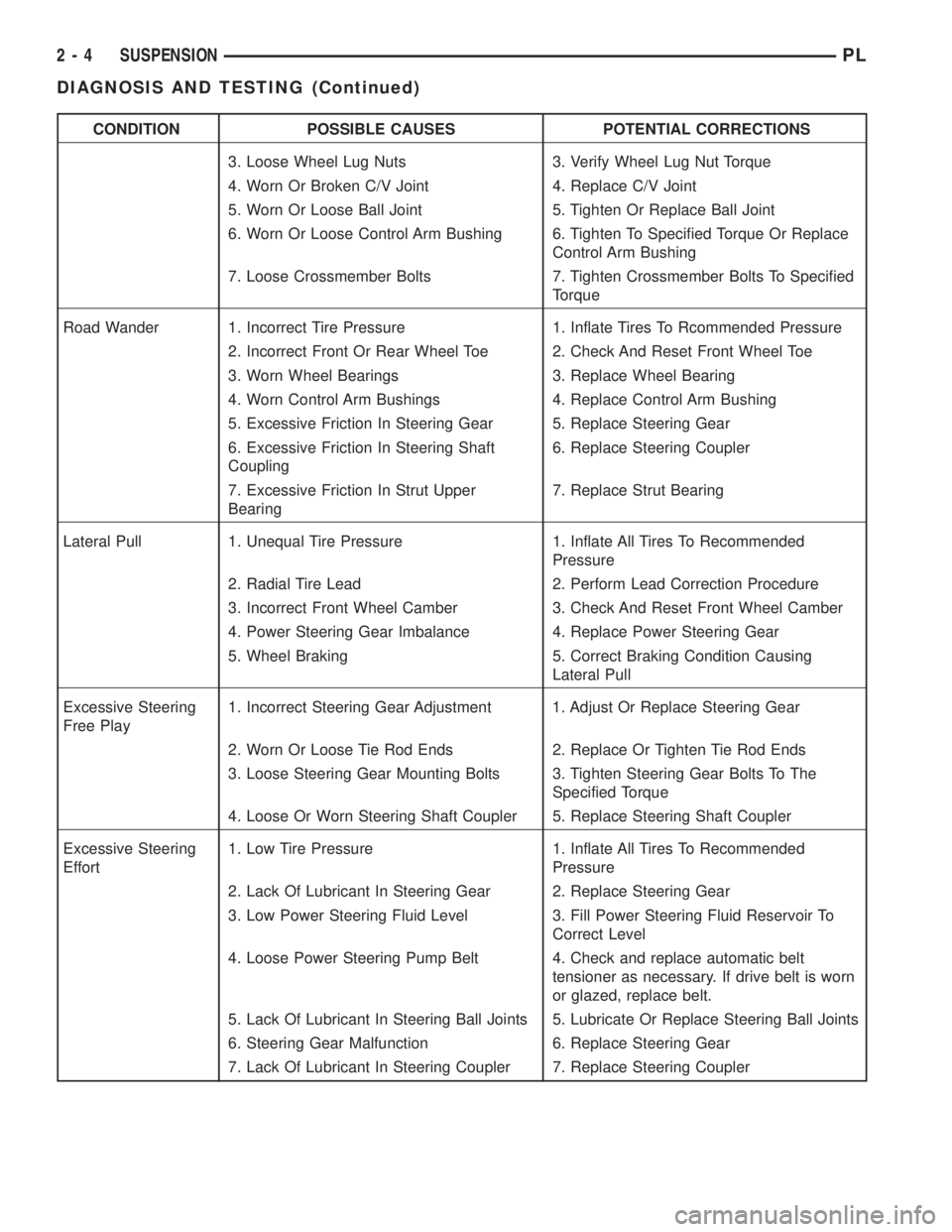
CONDITION POSSIBLE CAUSES POTENTIAL CORRECTIONS
3. Loose Wheel Lug Nuts 3. Verify Wheel Lug Nut Torque
4. Worn Or Broken C/V Joint 4. Replace C/V Joint
5. Worn Or Loose Ball Joint 5. Tighten Or Replace Ball Joint
6. Worn Or Loose Control Arm Bushing 6. Tighten To Specified Torque Or Replace
Control Arm Bushing
7. Loose Crossmember Bolts 7. Tighten Crossmember Bolts To Specified
Torque
Road Wander 1. Incorrect Tire Pressure 1. Inflate Tires To Rcommended Pressure
2. Incorrect Front Or Rear Wheel Toe 2. Check And Reset Front Wheel Toe
3. Worn Wheel Bearings 3. Replace Wheel Bearing
4. Worn Control Arm Bushings 4. Replace Control Arm Bushing
5. Excessive Friction In Steering Gear 5. Replace Steering Gear
6. Excessive Friction In Steering Shaft
Coupling6. Replace Steering Coupler
7. Excessive Friction In Strut Upper
Bearing7. Replace Strut Bearing
Lateral Pull 1. Unequal Tire Pressure 1. Inflate All Tires To Recommended
Pressure
2. Radial Tire Lead 2. Perform Lead Correction Procedure
3. Incorrect Front Wheel Camber 3. Check And Reset Front Wheel Camber
4. Power Steering Gear Imbalance 4. Replace Power Steering Gear
5. Wheel Braking 5. Correct Braking Condition Causing
Lateral Pull
Excessive Steering
Free Play1. Incorrect Steering Gear Adjustment 1. Adjust Or Replace Steering Gear
2. Worn Or Loose Tie Rod Ends 2. Replace Or Tighten Tie Rod Ends
3. Loose Steering Gear Mounting Bolts 3. Tighten Steering Gear Bolts To The
Specified Torque
4. Loose Or Worn Steering Shaft Coupler 5. Replace Steering Shaft Coupler
Excessive Steering
Effort1. Low Tire Pressure 1. Inflate All Tires To Recommended
Pressure
2. Lack Of Lubricant In Steering Gear 2. Replace Steering Gear
3. Low Power Steering Fluid Level 3. Fill Power Steering Fluid Reservoir To
Correct Level
4. Loose Power Steering Pump Belt 4. Check and replace automatic belt
tensioner as necessary. If drive belt is worn
or glazed, replace belt.
5. Lack Of Lubricant In Steering Ball Joints 5. Lubricate Or Replace Steering Ball Joints
6. Steering Gear Malfunction 6. Replace Steering Gear
7. Lack Of Lubricant In Steering Coupler 7. Replace Steering Coupler
2 - 4 SUSPENSIONPL
DIAGNOSIS AND TESTING (Continued)
Page 111 of 1285
CAUTION: Use only a new brake booster input rod-
to-brake pedal retaining clip to ensure proper
retainment.
(4) Connect the power brake booster input rod-to-
brake pedal pin. Install a new retaining clip. Do not
use the old clip.
(5) Connect all previously removed vacuum hoses
to the vacuum check valve (Fig. 49).
(6) If the vehicle is equipped with ABS, install the
ICU mounting bracket on the frame rail using its
three bolts. Tighten the nuts to a torque of 23 N´m
(200 in. lbs.).
(7) If the vehicle is equipped with ABS, reinstall
the ICU. Refer to INTEGRATED CONTROL UNIT in
REMOVAL AND INSTALLATION within the
ANTILOCK BRAKE SYSTEM section of this service
manual group for the procedure.
(8) Install the master cylinder. For the master cyl-
inder without ABS removal and installation proce-
dure, refer to MASTER CYLINDER in this section of
this service manual group. For the master cylinder
with ABS removal and installation procedure, refer
to MASTER CYLINDER in the ANTILOCK BRAKE
SYSTEM section of this service manual group.
(9) Position the battery tray back in place. Install
the two bolts, then the two nuts mounting the bat-
tery tray to its bracket (Fig. 48). Tighten the two
bolts and nuts to a torque of 34 N´m (25 ft. lbs.).
(10) Reinstall the air cleaner box onto its grom-
meted alignment post (Fig. 48).
(11) Install the one nut and one bolt securing the
air cleaner box in place, then connect the wiring har-
ness connector at the air inlet sensor.
(12) Install the battery and clamp it in place.
(13) Connect the positive, then the negative
(ground) cable on the battery.
(14) Adjust the stop lamp switch as necessary.
Refer to STOP LAMP SWITCH in the ADJUST-
MENTS section of this group.
(15) Bleed the base brake system.
(16) Road test the vehicle to ensure proper opera-
tion of the brakes.
PROPORTIONING VALVE
NOTE: Before proceeding with this procedure,
review SERVICE WARNINGS AND CAUTIONS at the
beginning of REMOVAL AND INSTALLATION in this
section.
REMOVAL
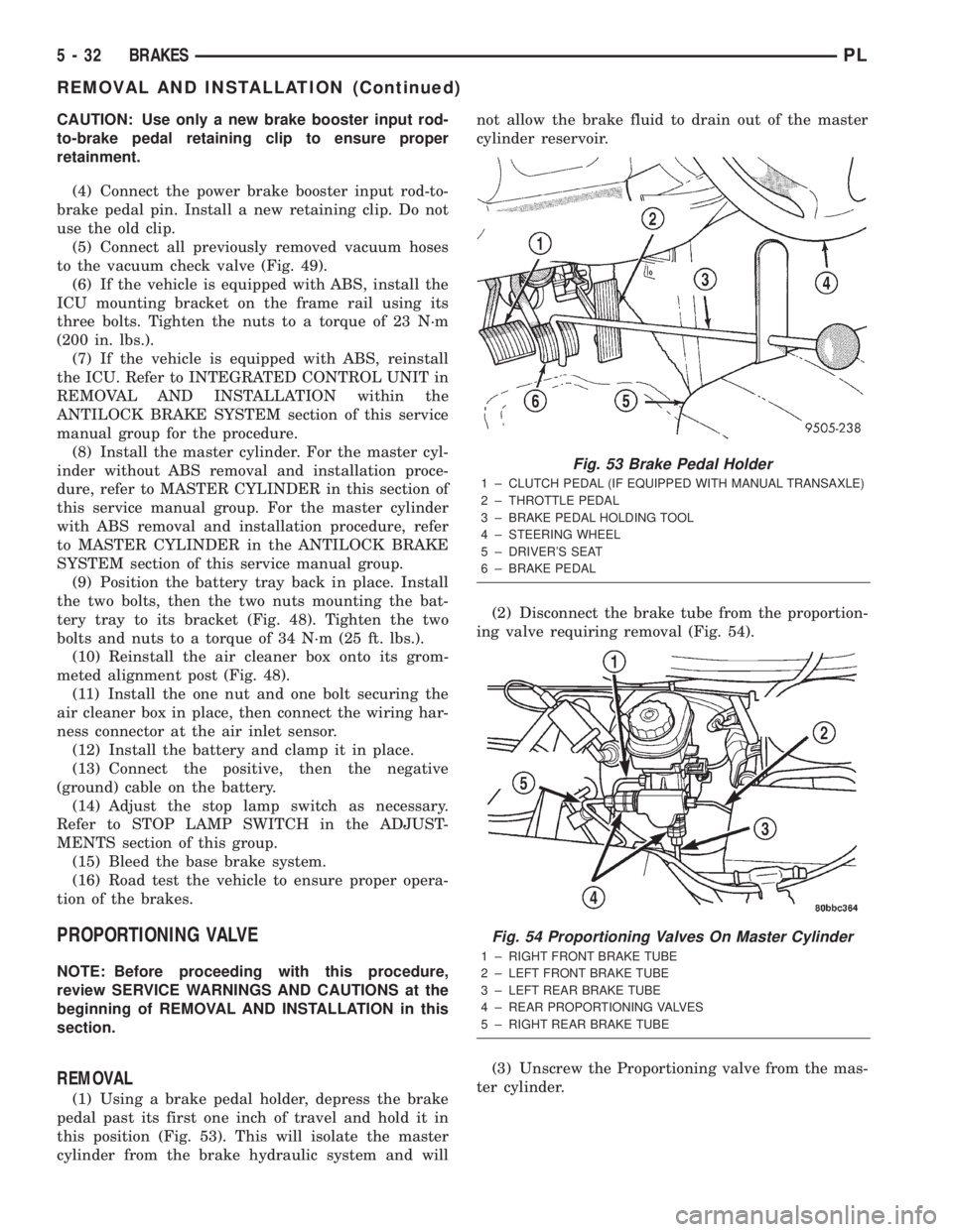
(1) Using a brake pedal holder, depress the brake
pedal past its first one inch of travel and hold it in
this position (Fig. 53). This will isolate the master
cylinder from the brake hydraulic system and willnot allow the brake fluid to drain out of the master
cylinder reservoir.
(2) Disconnect the brake tube from the proportion-
ing valve requiring removal (Fig. 54).
(3) Unscrew the Proportioning valve from the mas-
ter cylinder.
Fig. 53 Brake Pedal Holder
1 ± CLUTCH PEDAL (IF EQUIPPED WITH MANUAL TRANSAXLE)
2 ± THROTTLE PEDAL
3 ± BRAKE PEDAL HOLDING TOOL
4 ± STEERING WHEEL
5 ± DRIVER'S SEAT
6 ± BRAKE PEDAL
Fig. 54 Proportioning Valves On Master Cylinder
1 ± RIGHT FRONT BRAKE TUBE
2 ± LEFT FRONT BRAKE TUBE
3 ± LEFT REAR BRAKE TUBE
4 ± REAR PROPORTIONING VALVES
5 ± RIGHT REAR BRAKE TUBE
5 - 32 BRAKESPL
REMOVAL AND INSTALLATION (Continued)
Page 142 of 1285
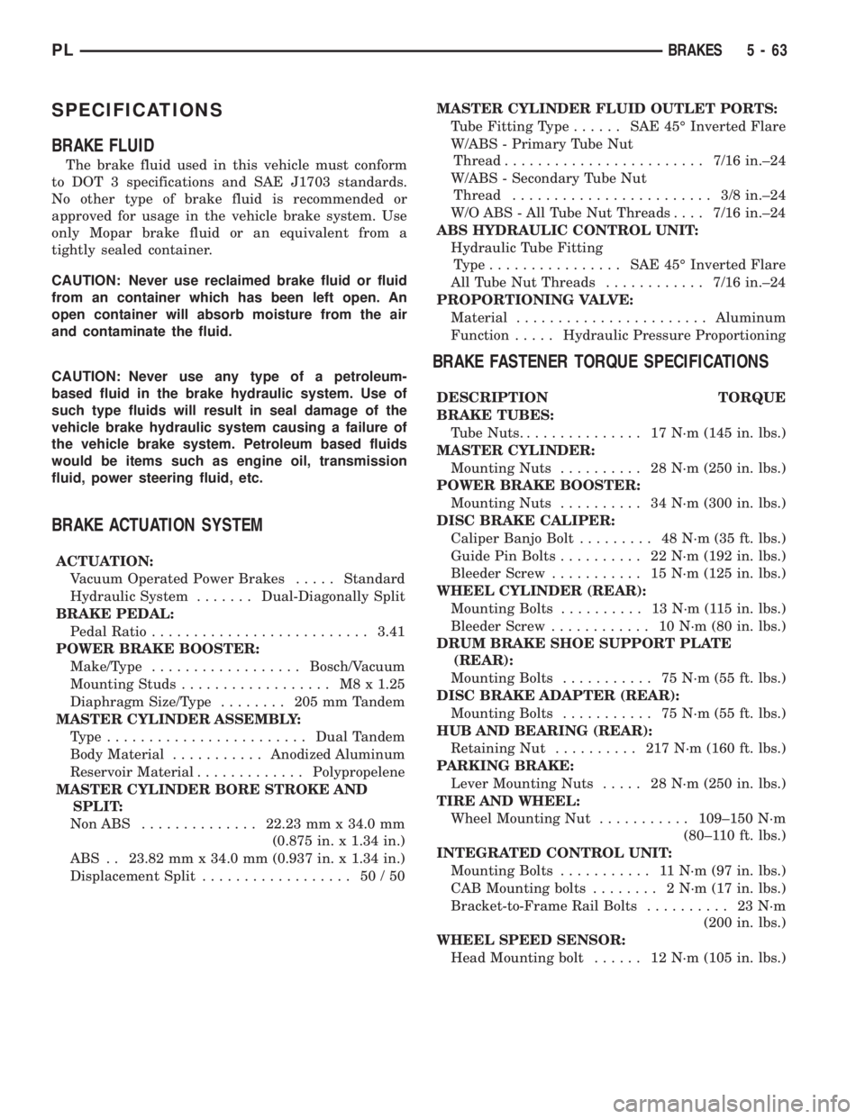
SPECIFICATIONS
BRAKE FLUID
The brake fluid used in this vehicle must conform
to DOT 3 specifications and SAE J1703 standards.
No other type of brake fluid is recommended or
approved for usage in the vehicle brake system. Use
only Mopar brake fluid or an equivalent from a
tightly sealed container.
CAUTION: Never use reclaimed brake fluid or fluid
from an container which has been left open. An
open container will absorb moisture from the air
and contaminate the fluid.
CAUTION: Never use any type of a petroleum-
based fluid in the brake hydraulic system. Use of
such type fluids will result in seal damage of the
vehicle brake hydraulic system causing a failure of
the vehicle brake system. Petroleum based fluids
would be items such as engine oil, transmission
fluid, power steering fluid, etc.
BRAKE ACTUATION SYSTEM
ACTUATION:
Vacuum Operated Power Brakes.....Standard
Hydraulic System.......Dual-Diagonally Split
BRAKE PEDAL:
Pedal Ratio..........................3.41
POWER BRAKE BOOSTER:
Make/Type..................Bosch/Vacuum
Mounting Studs.................. M8x1.25
Diaphragm Size/Type........ 205mmTandem
MASTER CYLINDER ASSEMBLY:
Type ........................Dual Tandem
Body Material...........Anodized Aluminum
Reservoir Material.............Polypropelene
MASTER CYLINDER BORE STROKE AND
SPLIT:
NonABS ..............22.23 mm x 34.0 mm
(0.875 in. x 1.34 in.)
ABS . . 23.82 mm x 34.0 mm (0.937 in. x 1.34 in.)
Displacement Split.................. 50/50MASTER CYLINDER FLUID OUTLET PORTS:
Tube Fitting Type...... SAE45ÉInverted Flare
W/ABS - Primary Tube Nut
Thread........................7/16 in.±24
W/ABS - Secondary Tube Nut
Thread........................ 3/8in.±24
W/O ABS - All Tube Nut Threads....7/16 in.±24
ABS HYDRAULIC CONTROL UNIT:
Hydraulic Tube Fitting
Type................ SAE45ÉInverted Flare
All Tube Nut Threads............7/16 in.±24
PROPORTIONING VALVE:
Material.......................Aluminum
Function.....Hydraulic Pressure Proportioning
BRAKE FASTENER TORQUE SPECIFICATIONS
DESCRIPTION TORQUE
BRAKE TUBES:
Tube Nuts............... 17N´m(145 in. lbs.)
MASTER CYLINDER:
Mounting Nuts.......... 28N´m(250 in. lbs.)
POWER BRAKE BOOSTER:
Mounting Nuts.......... 34N´m(300 in. lbs.)
DISC BRAKE CALIPER:
Caliper Banjo Bolt......... 48N´m(35ft.lbs.)
Guide Pin Bolts.......... 22N´m(192 in. lbs.)
Bleeder Screw........... 15N´m(125 in. lbs.)
WHEEL CYLINDER (REAR):
Mounting Bolts.......... 13N´m(115in.lbs.)
Bleeder Screw............ 10N´m(80in.lbs.)
DRUM BRAKE SHOE SUPPORT PLATE
(REAR):
Mounting Bolts........... 75N´m(55ft.lbs.)
DISC BRAKE ADAPTER (REAR):
Mounting Bolts........... 75N´m(55ft.lbs.)
HUB AND BEARING (REAR):
Retaining Nut.......... 217N´m(160 ft. lbs.)
PARKING BRAKE:
Lever Mounting Nuts..... 28N´m(250 in. lbs.)
TIRE AND WHEEL:
Wheel Mounting Nut...........109±150 N´m
(80±110 ft. lbs.)
INTEGRATED CONTROL UNIT:
Mounting Bolts........... 11N´m(97in.lbs.)
CAB Mounting bolts........ 2N´m(17in.lbs.)
Bracket-to-Frame Rail Bolts.......... 23N´m
(200 in. lbs.)
WHEEL SPEED SENSOR:
Head Mounting bolt...... 12N´m(105 in. lbs.)
PLBRAKES 5 - 63
Page 145 of 1285
NOISE AND BRAKE PEDAL FEEL
During ABS braking, some brake pedal movement
may be felt. In addition, ABS braking will create
ticking, popping, or groaning noises heard by the
driver. This is normal and is due to pressurized fluid
being transferred between the master cylinder and
the brakes. If ABS operation occurs during hard
braking, some pulsation may be felt in the vehicle
body due to fore-and-aft movement of the suspension
as brake pressures are modulated.
At the end of an ABS stop, ABS is turned off when
the vehicle is slowed to a speed of 3±4 mph. There
may be a slight brake pedal drop anytime that the
ABS is deactivated, such as at the end of the stop
when the vehicle speed is less than 3 mph or during
an ABS stop where ABS is no longer required. These
conditions exist when a vehicle is being stopped on a
road surface with patches of ice, loose gravel, or sand
on it. Also, stopping a vehicle on a bumpy road sur-
face activates ABS because of the wheel hop caused
by the bumps.
TIRE NOISE AND MARKS
Although the ABS system prevents complete wheel
lockup, some wheel slip is desired in order to achieve
optimum braking performance. Wheel slip is defined
as follows: 0 percent slip means the wheel is rolling
freely and 100 percent slip means the wheel is fully
locked. During brake pressure modulation, wheel slip
is allowed to reach up to 25±30 percent. This means
that the wheel rolling velocity is 25±30 percent less
than that of a free rolling wheel at a given vehicle
speed. This slip may result in some tire chirping,
depending on the road surface. This sound should not
be interpreted as total wheel lockup.
Complete wheel lockup normally leaves black tire
marks on dry pavement. The ABS will not leave dark
black tire marks since the wheel never reaches a
fully locked condition. However, tire marks may be
noticeable as light patched marks.
START-UP CYCLE
When the ignition is turned on, a popping sound
and a slight brake pedal movement may be noticed.
The ABS warning lamp will also be on for up to 5
seconds after the ignition is turned on. When the
vehicle is first driven off, a humming may be heard
or felt by the driver at approximately 20±40 kph
(12±25 mph). All of these conditions are a normal
function of ABS as the system is performing a diag-
nosis check.
PREMATURE ABS CYCLING
Symptoms of premature ABS cycling include: click-
ing sounds from the solenoid valves; pump/motor
running; and pulsations in the brake pedal. Prema-ture ABS cycling can occur at any braking rate of the
vehicle and on any type of road surface. Neither the
red BRAKE warning lamp, nor the amber ABS warn-
ing lamp, illuminate and no fault codes are stored in
the CAB.
Premature ABS cycling is a condition that needs to
be correctly assessed when diagnosing problems with
the antilock brake system. It may be necessary to use
a DRB scan tool to detect and verify premature ABS
cycling.
Check the following common causes when diagnos-
ing premature ABS cycling: damaged tone wheels;
incorrect tone wheels; damaged steering knuckle
wheel speed sensor mounting bosses; loose wheel
speed sensor mounting bolts; excessive tone wheel
runout; or an excessively large tone wheel-to-wheel
speed sensor air gap. Give special attention to these
components when diagnosing a vehicle exhibiting
premature ABS cycling.
After diagnosing the defective component, repair or
replace it as required. When the component repair or
replacement is completed, test drive the vehicle to
verify that premature ABS cycling has been cor-
rected.
ANTILOCK BRAKE SYSTEM COMPONENTS
The following is a detailed description of the
antilock brake system components. For information
on servicing base brake system components used in
conjunction with these components, see the BASE
BRAKE SYSTEM found at the beginning of this ser-
vice manual group.
MASTER CYLINDER
A vehicle equipped with ABS uses a different mas-
ter cylinder than a vehicle that is not equipped with
ABS. Vehicles equipped with ABS use a center port
master cylinder with only two outlet ports (Fig. 1).
The brake tubes from the primary and secondary
outlet ports on the master cylinder go directly to the
integrated control unit (ICU).
The master cylinder mounts to the power brake
booster in the same manner a non-ABS master cylin-
der does.
INTEGRATED CONTROL UNIT (ICU)
The hydraulic control unit (HCU) and the control-
ler antilock brake (CAB) used with this antilock
brake system are combined (integrated) into one
unit, which is called the integrated control unit (ICU)
(Fig. 2). The ICU is located on the driver's side of the
vehicle, and is mounted to the left front frame rail
below the master cylinder (Fig. 1).
5 - 66 BRAKESPL
DESCRIPTION AND OPERATION (Continued)
Page 148 of 1285
AMBER ABS WARNING LAMP
The amber ABS warning lamp is located in the
instrument cluster. The purpose of the warning lamp
is discussed in detail below.
When the ignition key is turned to the ON posi-
tion, the amber ABS warning lamp is lit until the
CAB completes its self-tests and turns off the lamp
(approximately 4 seconds). The amber ABS warning
lamp will illuminate when the CAB detects a condi-
tion that results in the shutdown of ABS function.
The CAB sends a message to the mechanical instu-
ment cluster (MIC) instructing it to turn on the
amber ABS warning lamp.
Under most conditions, when the amber ABS warn-
ing lamp is on, only the ABS function of the brake
system is affected; The electronic brake distribution
(EBD), the base brake system and the ability to stop
the vehicle are not affected.
WHEEL SPEED SENSOR (WSS)
At each wheel of the vehicle there is one wheel
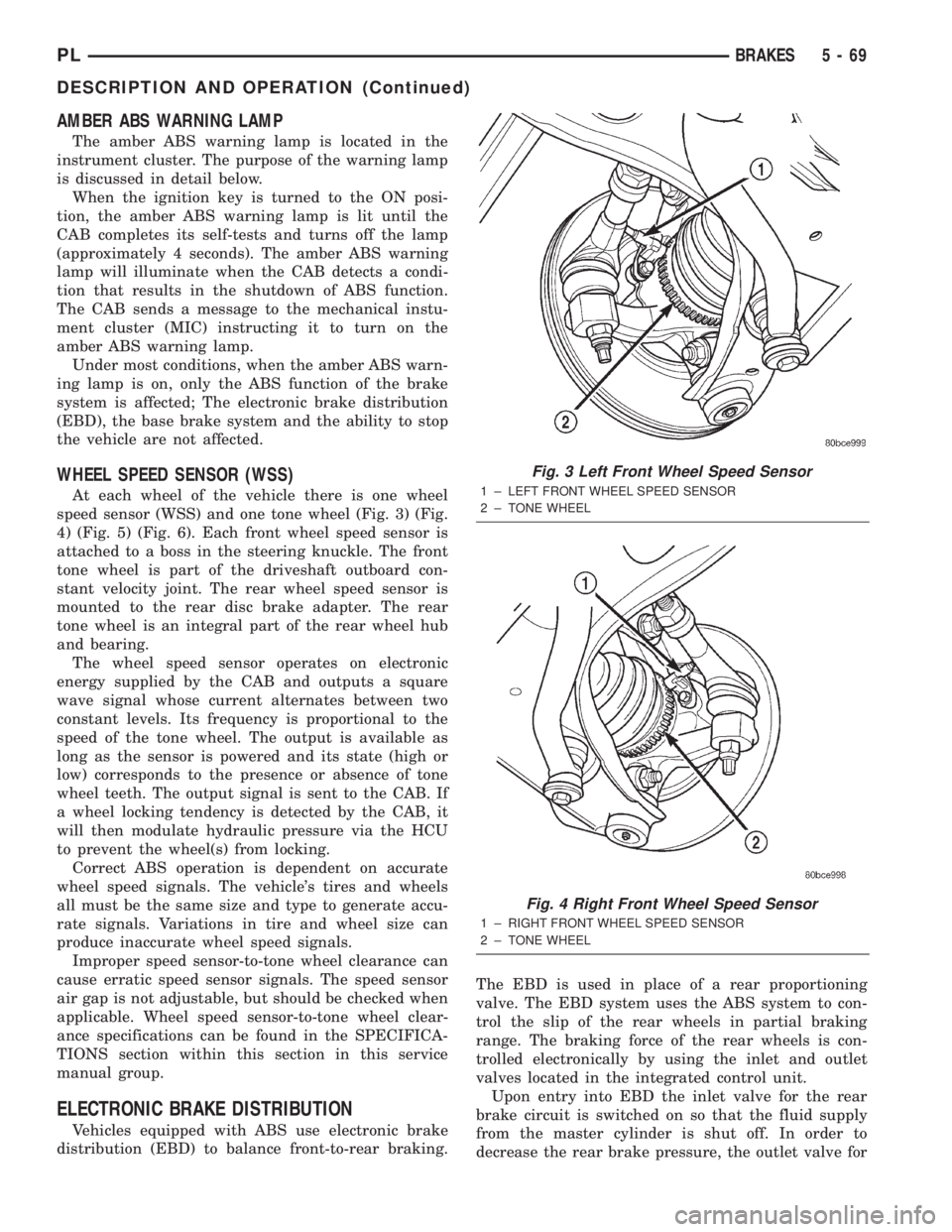
speed sensor (WSS) and one tone wheel (Fig. 3) (Fig.
4) (Fig. 5) (Fig. 6). Each front wheel speed sensor is
attached to a boss in the steering knuckle. The front
tone wheel is part of the driveshaft outboard con-
stant velocity joint. The rear wheel speed sensor is
mounted to the rear disc brake adapter. The rear
tone wheel is an integral part of the rear wheel hub
and bearing.
The wheel speed sensor operates on electronic
energy supplied by the CAB and outputs a square
wave signal whose current alternates between two
constant levels. Its frequency is proportional to the
speed of the tone wheel. The output is available as
long as the sensor is powered and its state (high or
low) corresponds to the presence or absence of tone
wheel teeth. The output signal is sent to the CAB. If
a wheel locking tendency is detected by the CAB, it
will then modulate hydraulic pressure via the HCU
to prevent the wheel(s) from locking.
Correct ABS operation is dependent on accurate
wheel speed signals. The vehicle's tires and wheels
all must be the same size and type to generate accu-
rate signals. Variations in tire and wheel size can
produce inaccurate wheel speed signals.
Improper speed sensor-to-tone wheel clearance can
cause erratic speed sensor signals. The speed sensor
air gap is not adjustable, but should be checked when
applicable. Wheel speed sensor-to-tone wheel clear-
ance specifications can be found in the SPECIFICA-
TIONS section within this section in this service
manual group.
ELECTRONIC BRAKE DISTRIBUTION
Vehicles equipped with ABS use electronic brake
distribution (EBD) to balance front-to-rear braking.The EBD is used in place of a rear proportioning
valve. The EBD system uses the ABS system to con-
trol the slip of the rear wheels in partial braking
range. The braking force of the rear wheels is con-
trolled electronically by using the inlet and outlet
valves located in the integrated control unit.
Upon entry into EBD the inlet valve for the rear
brake circuit is switched on so that the fluid supply
from the master cylinder is shut off. In order to
decrease the rear brake pressure, the outlet valve for
Fig. 3 Left Front Wheel Speed Sensor
1 ± LEFT FRONT WHEEL SPEED SENSOR
2 ± TONE WHEEL
Fig. 4 Right Front Wheel Speed Sensor
1 ± RIGHT FRONT WHEEL SPEED SENSOR
2 ± TONE WHEEL
PLBRAKES 5 - 69
DESCRIPTION AND OPERATION (Continued)
Page 811 of 1285
CAUTION: After removing the steering knuckle from
the ball joint stud, do not pull outward on the knuckle.
Pulling the steering knuckle outward at this point can
separate the inner C/V joint on the driveshaft. Refer to
FRONT DRIVESHAFTS in the DIFFERENTIAL AND
DRIVELINE group for further information.
NOTE: Use caution when separating the ball joint
stud from the steering knuckle, so the ball joint seal
does not get cut.
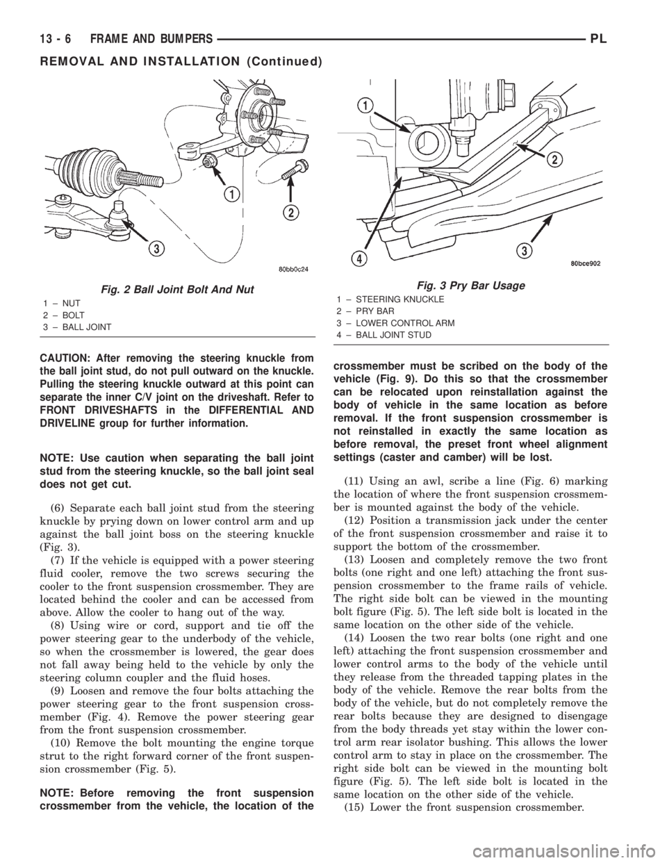
(6) Separate each ball joint stud from the steering
knuckle by prying down on lower control arm and up
against the ball joint boss on the steering knuckle
(Fig. 3).
(7) If the vehicle is equipped with a power steering
fluid cooler, remove the two screws securing the
cooler to the front suspension crossmember. They are
located behind the cooler and can be accessed from
above. Allow the cooler to hang out of the way.
(8) Using wire or cord, support and tie off the
power steering gear to the underbody of the vehicle,
so when the crossmember is lowered, the gear does
not fall away being held to the vehicle by only the
steering column coupler and the fluid hoses.
(9) Loosen and remove the four bolts attaching the
power steering gear to the front suspension cross-
member (Fig. 4). Remove the power steering gear
from the front suspension crossmember.
(10) Remove the bolt mounting the engine torque
strut to the right forward corner of the front suspen-
sion crossmember (Fig. 5).
NOTE: Before removing the front suspension
crossmember from the vehicle, the location of thecrossmember must be scribed on the body of the
vehicle (Fig. 9). Do this so that the crossmember
can be relocated upon reinstallation against the
body of vehicle in the same location as before
removal. If the front suspension crossmember is
not reinstalled in exactly the same location as
before removal, the preset front wheel alignment
settings (caster and camber) will be lost.
(11) Using an awl, scribe a line (Fig. 6) marking
the location of where the front suspension crossmem-
ber is mounted against the body of the vehicle.
(12) Position a transmission jack under the center
of the front suspension crossmember and raise it to
support the bottom of the crossmember.
(13) Loosen and completely remove the two front
bolts (one right and one left) attaching the front sus-
pension crossmember to the frame rails of vehicle.
The right side bolt can be viewed in the mounting
bolt figure (Fig. 5). The left side bolt is located in the
same location on the other side of the vehicle.
(14) Loosen the two rear bolts (one right and one
left) attaching the front suspension crossmember and
lower control arms to the body of the vehicle until
they release from the threaded tapping plates in the
body of the vehicle. Remove the rear bolts from the
body of the vehicle, but do not completely remove the
rear bolts because they are designed to disengage
from the body threads yet stay within the lower con-
trol arm rear isolator bushing. This allows the lower
control arm to stay in place on the crossmember. The
right side bolt can be viewed in the mounting bolt
figure (Fig. 5). The left side bolt is located in the
same location on the other side of the vehicle.
(15) Lower the front suspension crossmember.
Fig. 2 Ball Joint Bolt And Nut
1 ± NUT
2 ± BOLT
3 ± BALL JOINT
Fig. 3 Pry Bar Usage
1 ± STEERING KNUCKLE
2±PRYBAR
3 ± LOWER CONTROL ARM
4 ± BALL JOINT STUD
13 - 6 FRAME AND BUMPERSPL
REMOVAL AND INSTALLATION (Continued)
Page 813 of 1285
(3) Start the two rear crossmember mounting bolts
into the tapping plates mounted in the body. The
right side bolt can be viewed in the mounting bolt
figure (Fig. 5). The left side bolt is located in the
same location on the other side of the vehicle. Next,
install the two front mounting bolts attaching front
suspension crossmember to frame rails of vehicle.
Lightly tighten all four mounting bolts to a approxi-
mately 2 N´m (20 in. lbs.) to hold the front suspen-
sion crossmember in position.
NOTE: When reinstalling the front suspension
crossmember back in the vehicle, it is very impor-
tant that the crossmember be attached to the body
in exactly the same spot as when it was removed.
Otherwise, the vehicle's wheel alignment settings
(caster and camber) will be lost.
(4) Using a soft face hammer, tap the front suspen-
sion crossmember back-and-forth or side-to-side until
it is aligned with the previously scribed positioning
marks on the body of the vehicle (Fig. 6). Once the
front suspension crossmember is correctly positioned,
tighten the rear two crossmember mounting bolts to
a torque of 203 N´m (150 ft. lbs.), then tighten the
front two crossmember mounting bolts to a torque of
142 N´m (105 ft. lbs.).
(5) Tighten the lower control arm front pivot bolts
to a torque of 163 N´m (120 ft. lbs.).
(6) Attach the steering gear to the front suspen-
sion crossmember (Fig. 4). Install the four power
steering gear mounting bolts. Tighten the mounting
bolts to a torque of 61 N´m (45 ft. lbs.).
(7) Remove the wire or cord suspending the power
steering gear to the underbody.
(8) If the vehicle is equipped with a power steering
fluid cooler, install the two screws securing the cooler
to the front suspension crossmember. They are
located behind the cooler.
(9)
Install each ball joint stud into the steering
knuckle aligning the bolt hole in the knuckle boss with
the notch formed in the side of the ball joint stud.
(10) Install a new ball joint stud pinch bolt and
nut (Fig. 2). Tighten the nut to a torque of 95 N´m
(70 ft. lbs.).
(11) Fasten the engine torque strut to the right
forward corner of the front suspension crossmember
using its mounting bolt (Fig. 5). Follow the procedure
described in the ENGINE service manual group to
properly align and tighten the torque strut and it's
mounting bolts.
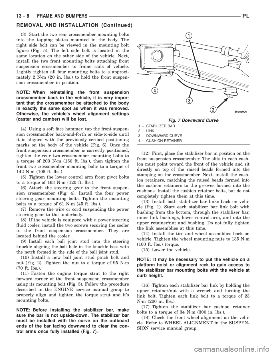
NOTE: Before installing the stabilizer bar, make
sure the bar is not upside-down. The stabilizer bar
must be installed with the curve on the outboard
ends of the bar facing downward to clear the con-
trol arms once fully installed (Fig. 7).(12)
First, place the stabilizer bar in position on the
front suspension crossmember. The slits in each cush-
ion must point toward the front of the vehicle and sit
directly on top of the raised beads formed into the
stamping on the crossmember. Next, install the cush-
ion retainers, matching the raised beads formed into
the cushion retainers to the grooves formed into the
cushions. Install the cushion retainer bolts, but do not
completely tighten them at this time.
(13) Install both stabilizer bar links back on vehi-
cle (Fig. 1). Start each stabilizer bar link bolt with
bushing from the bottom, through the stabilizer bar,
inner link bushings, lower control arm, and into the
upper retainer/nut and bushing. Do not fully tighten
the link assemblies at this time.
(14) Install the tire and wheel assemblies back on
vehicle. Tighten the wheel mounting nuts to 135 N´m
(100 ft. lbs.) torque.
(15) Lower the vehicle.
NOTE: It may be necessary to put the vehicle on a
platform hoist or alignment rack to gain access to
the stabilizer bar mounting bolts with the vehicle at
curb height.
(16) Tighten each stabilizer bar link by holding the
upper retainer/nut with a wrench and turning the
link bolt. Tighten each link bolt to a torque of 23
N´m (200 in. lbs.).
(17) Tighten the stabilizer bar cushion retainer
bolts to a torque of 34 N´m (300 in. lbs.).
(18) Check the front wheel alignment on the vehi-
cle. Refer to WHEEL ALIGNMENT in the SUSPEN-
SION service manual group.
Fig. 7 Downward Curve
1 ± STABILIZER BAR
2 ± LINK
3 ± DOWNWARD CURVE
4 ± CUSHION RETAINER
13 - 8 FRAME AND BUMPERSPL
REMOVAL AND INSTALLATION (Continued)