2000 DODGE NEON power steering fluid
[x] Cancel search: power steering fluidPage 909 of 1285

(25) Turn the key to OFF and remove the scan tool
from the vehicle.
(26) Test the operation of the horn, wipers and any
other functions that are steering column operated. If
applicable, reset the radio and the clock.
(27) If the steering column is a tilt column, verify
the tilt mechanism operates properly.
(28) Road test the vehicle to ensure proper opera-
tion of the steering system and the speed control sys-
tem.
STEERING COLUMN LOWER COUPLING
NOTE: Before proceeding with this removal and
installation procedure, review SERVICE WARNINGS
AND CAUTIONS at the beginning of REMOVAL AND
INSTALLATION in this section and in STEERING
GEAR.
REMOVAL
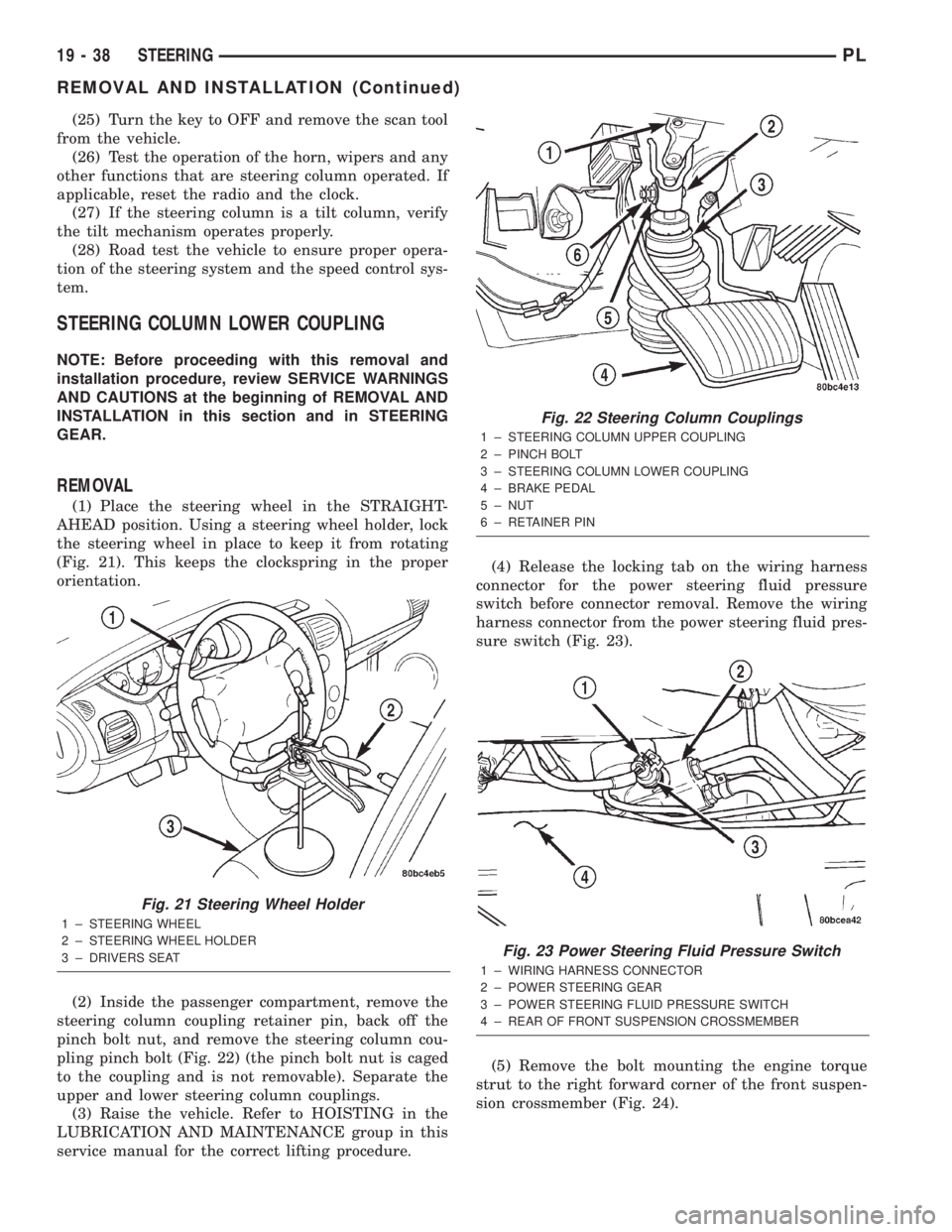
(1) Place the steering wheel in the STRAIGHT-
AHEAD position. Using a steering wheel holder, lock
the steering wheel in place to keep it from rotating
(Fig. 21). This keeps the clockspring in the proper
orientation.
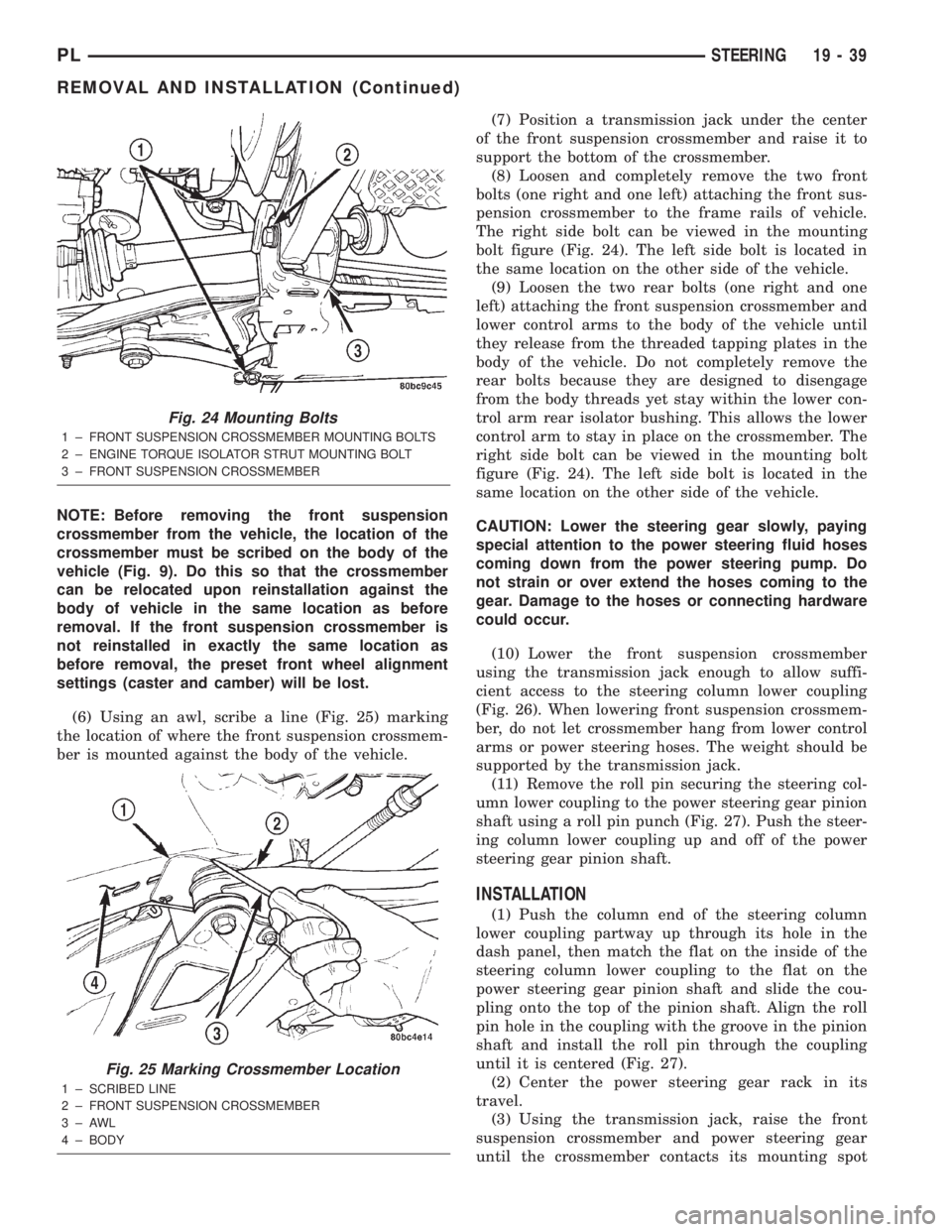
(2) Inside the passenger compartment, remove the
steering column coupling retainer pin, back off the
pinch bolt nut, and remove the steering column cou-
pling pinch bolt (Fig. 22) (the pinch bolt nut is caged
to the coupling and is not removable). Separate the
upper and lower steering column couplings.
(3) Raise the vehicle. Refer to HOISTING in the
LUBRICATION AND MAINTENANCE group in this
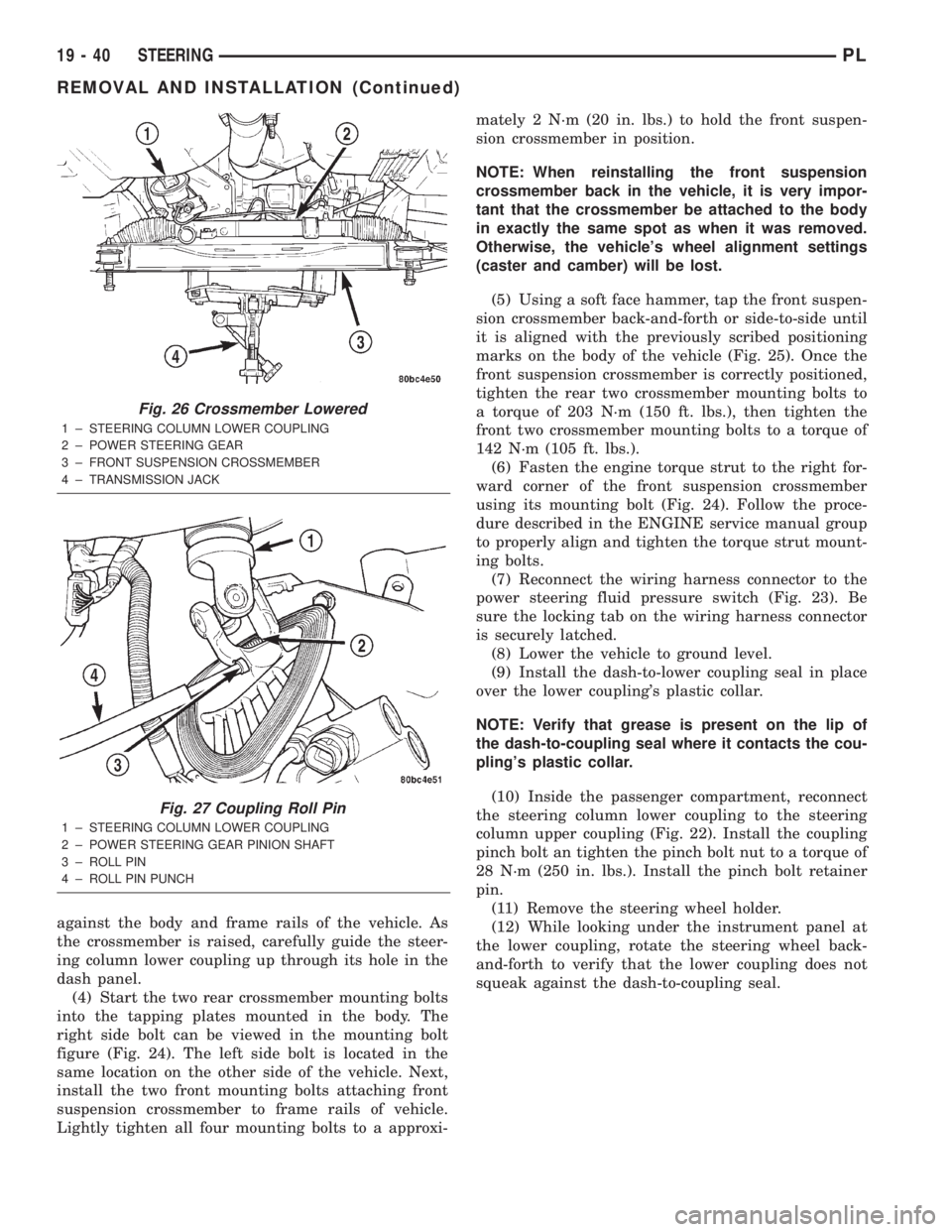
service manual for the correct lifting procedure.(4) Release the locking tab on the wiring harness
connector for the power steering fluid pressure
switch before connector removal. Remove the wiring
harness connector from the power steering fluid pres-
sure switch (Fig. 23).
(5) Remove the bolt mounting the engine torque
strut to the right forward corner of the front suspen-
sion crossmember (Fig. 24).
Fig. 21 Steering Wheel Holder
1 ± STEERING WHEEL
2 ± STEERING WHEEL HOLDER
3 ± DRIVERS SEAT
Fig. 22 Steering Column Couplings
1 ± STEERING COLUMN UPPER COUPLING
2 ± PINCH BOLT
3 ± STEERING COLUMN LOWER COUPLING
4 ± BRAKE PEDAL
5 ± NUT
6 ± RETAINER PIN
Fig. 23 Power Steering Fluid Pressure Switch
1 ± WIRING HARNESS CONNECTOR
2 ± POWER STEERING GEAR
3 ± POWER STEERING FLUID PRESSURE SWITCH
4 ± REAR OF FRONT SUSPENSION CROSSMEMBER
19 - 38 STEERINGPL
REMOVAL AND INSTALLATION (Continued)
Page 910 of 1285

NOTE: Before removing the front suspension
crossmember from the vehicle, the location of the
crossmember must be scribed on the body of the
vehicle (Fig. 9). Do this so that the crossmember
can be relocated upon reinstallation against the
body of vehicle in the same location as before
removal. If the front suspension crossmember is
not reinstalled in exactly the same location as
before removal, the preset front wheel alignment
settings (caster and camber) will be lost.
(6) Using an awl, scribe a line (Fig. 25) marking
the location of where the front suspension crossmem-
ber is mounted against the body of the vehicle.(7) Position a transmission jack under the center
of the front suspension crossmember and raise it to
support the bottom of the crossmember.
(8) Loosen and completely remove the two front
bolts (one right and one left) attaching the front sus-
pension crossmember to the frame rails of vehicle.
The right side bolt can be viewed in the mounting
bolt figure (Fig. 24). The left side bolt is located in
the same location on the other side of the vehicle.
(9) Loosen the two rear bolts (one right and one
left) attaching the front suspension crossmember and
lower control arms to the body of the vehicle until
they release from the threaded tapping plates in the
body of the vehicle. Do not completely remove the
rear bolts because they are designed to disengage
from the body threads yet stay within the lower con-
trol arm rear isolator bushing. This allows the lower
control arm to stay in place on the crossmember. The
right side bolt can be viewed in the mounting bolt
figure (Fig. 24). The left side bolt is located in the
same location on the other side of the vehicle.
CAUTION: Lower the steering gear slowly, paying
special attention to the power steering fluid hoses
coming down from the power steering pump. Do
not strain or over extend the hoses coming to the
gear. Damage to the hoses or connecting hardware
could occur.
(10) Lower the front suspension crossmember
using the transmission jack enough to allow suffi-
cient access to the steering column lower coupling
(Fig. 26). When lowering front suspension crossmem-
ber, do not let crossmember hang from lower control
arms or power steering hoses. The weight should be
supported by the transmission jack.
(11) Remove the roll pin securing the steering col-
umn lower coupling to the power steering gear pinion
shaft using a roll pin punch (Fig. 27). Push the steer-
ing column lower coupling up and off of the power
steering gear pinion shaft.
INSTALLATION
(1) Push the column end of the steering column
lower coupling partway up through its hole in the
dash panel, then match the flat on the inside of the
steering column lower coupling to the flat on the
power steering gear pinion shaft and slide the cou-
pling onto the top of the pinion shaft. Align the roll
pin hole in the coupling with the groove in the pinion
shaft and install the roll pin through the coupling
until it is centered (Fig. 27).
(2) Center the power steering gear rack in its
travel.
(3) Using the transmission jack, raise the front
suspension crossmember and power steering gear
until the crossmember contacts its mounting spot
Fig. 24 Mounting Bolts
1 ± FRONT SUSPENSION CROSSMEMBER MOUNTING BOLTS
2 ± ENGINE TORQUE ISOLATOR STRUT MOUNTING BOLT
3 ± FRONT SUSPENSION CROSSMEMBER
Fig. 25 Marking Crossmember Location
1 ± SCRIBED LINE
2 ± FRONT SUSPENSION CROSSMEMBER
3±AWL
4 ± BODY
PLSTEERING 19 - 39
REMOVAL AND INSTALLATION (Continued)
Page 911 of 1285

against the body and frame rails of the vehicle. As
the crossmember is raised, carefully guide the steer-
ing column lower coupling up through its hole in the
dash panel.
(4) Start the two rear crossmember mounting bolts
into the tapping plates mounted in the body. The
right side bolt can be viewed in the mounting bolt
figure (Fig. 24). The left side bolt is located in the
same location on the other side of the vehicle. Next,
install the two front mounting bolts attaching front
suspension crossmember to frame rails of vehicle.
Lightly tighten all four mounting bolts to a approxi-mately 2 N´m (20 in. lbs.) to hold the front suspen-
sion crossmember in position.
NOTE: When reinstalling the front suspension
crossmember back in the vehicle, it is very impor-
tant that the crossmember be attached to the body
in exactly the same spot as when it was removed.
Otherwise, the vehicle's wheel alignment settings
(caster and camber) will be lost.
(5) Using a soft face hammer, tap the front suspen-
sion crossmember back-and-forth or side-to-side until
it is aligned with the previously scribed positioning
marks on the body of the vehicle (Fig. 25). Once the
front suspension crossmember is correctly positioned,
tighten the rear two crossmember mounting bolts to
a torque of 203 N´m (150 ft. lbs.), then tighten the
front two crossmember mounting bolts to a torque of
142 N´m (105 ft. lbs.).
(6) Fasten the engine torque strut to the right for-
ward corner of the front suspension crossmember
using its mounting bolt (Fig. 24). Follow the proce-
dure described in the ENGINE service manual group
to properly align and tighten the torque strut mount-
ing bolts.
(7) Reconnect the wiring harness connector to the
power steering fluid pressure switch (Fig. 23). Be
sure the locking tab on the wiring harness connector
is securely latched.
(8) Lower the vehicle to ground level.
(9) Install the dash-to-lower coupling seal in place
over the lower coupling's plastic collar.
NOTE: Verify that grease is present on the lip of
the dash-to-coupling seal where it contacts the cou-
pling's plastic collar.
(10) Inside the passenger compartment, reconnect
the steering column lower coupling to the steering
column upper coupling (Fig. 22). Install the coupling
pinch bolt an tighten the pinch bolt nut to a torque of
28 N´m (250 in. lbs.). Install the pinch bolt retainer
pin.
(11) Remove the steering wheel holder.
(12) While looking under the instrument panel at
the lower coupling, rotate the steering wheel back-
and-forth to verify that the lower coupling does not
squeak against the dash-to-coupling seal.
Fig. 26 Crossmember Lowered
1 ± STEERING COLUMN LOWER COUPLING
2 ± POWER STEERING GEAR
3 ± FRONT SUSPENSION CROSSMEMBER
4 ± TRANSMISSION JACK
Fig. 27 Coupling Roll Pin
1 ± STEERING COLUMN LOWER COUPLING
2 ± POWER STEERING GEAR PINION SHAFT
3 ± ROLL PIN
4 ± ROLL PIN PUNCH
19 - 40 STEERINGPL
REMOVAL AND INSTALLATION (Continued)
Page 1097 of 1285

(M) Check Engine Lamp (MIL) will illuminate during engine operation if this Diagnostic Trouble Code was recorded.
P0456 Evap Leak Monitor Small Leak
Detected
P0460 Fuel Level Unit No Change Over
MilesNo movement of fuel level sender detected.
P0461 Fuel Level Unit No Changeover
TimeNo level of fuel level sender detected.
P0462 Fuel Level Sending Unit Volts Too
LowFuel level sensor input below acceptable voltage.
P0463 Fuel Level Sending Unit Volts Too
HighFuel level sensor input above acceptable voltage.
P0500 (M) No Vehicle Speed Sensor Signal No vehicle speed sensor signal detected during road
load conditions.
P0505 (M) Idle Air Control Motor Circuits Replace
P0522 Oil Pressure Sens Low Oil pressure sensor input below acceptable voltage.
P0523 Oil Pressure Sens High Oil pressure sensor input above acceptable voltage.
P0551 (M) Power Steering Switch Failure Incorrect input state detected for the power steering
switch circuit. PL: High pressure seen at high speed.
P0600 (M) PCM Failure SPI Communications No communication detected between co-processors in
the control module.
P0601 (M) Internal Controller Failure Internal control module fault condition (check sum)
detected.
P0604 Internal Trans Controller Transmission control module RAM self test fault
detected. -Aisin transmission.
P0605 Internal Trans Controller Transmission control module ROM self test fault
detected -Aisin transmission.
P0622 (G) Generator Field Not Switching
ProperlyAn open or shorted condition detected in the generator
field control circuit.
P0645 A/C Clutch Relay Circuit An open or shorted condition detected in the A/C clutch
relay control circuit.
P0700 (M) EATX Controller DTC Present This SBEC III or JTEC DTC indicates that the EATX or
Aisin controller has an active fault and has illuminated
the MIL via a CCD (EATX) or SCI (Aisin) message. The
specific fault must be acquired from the EATX via CCD
or from the Aisin via ISO-9141.
P0703 (M) Brake Switch Stuck Pressed or
ReleasedIncorrect input state detected in the brake switch circuit.
(Changed from P1595).
P0711 Trans Temp Sensor, No Temp Rise
After StartRelationship between the transmission temperature and
overdrive operation and/or TCC operation indicates a
failure of the Transmission Temperature Sensor. OBD II
Rationality.
P0712 Trans Temp Sensor Voltage Too
LowTransmission fluid temperature sensor input below
acceptable voltage.
P0713 Trans Temp Sensor Voltage Too
HighTransmission fluid temperature sensor input above
acceptable voltage.
P0720 Low Output SPD Sensor RPM,
Above 15 MPHThe relationship between the Output Shaft Speed
Sensor and vehicle speed is not within acceptable
limits.
25 - 10 EMISSION CONTROL SYSTEMSPL
DESCRIPTION AND OPERATION (Continued)