2000 DODGE NEON air condition
[x] Cancel search: air conditionPage 1 of 1285

GROUP TAB LOCATORINIntroductionINaIntroduction0Lubrication and Maintenance2Suspension3Differential and Driveline5Brakes6Clutch7Cooling8ABattery8BStarting8CCharging System8DIgnition System8EInstrument Panel and Systems8EaInstrument Panel and Systems8FAudio System8GHorns8HVehicle Speed Control System8JTurn Signal and Flashers8KWindshield Wipers and Washers8LLamps8LaLamps8MRestraint System8NElectrically Heated Systems8OPower Distribution Systems8PPower Door Locks8QImmobilizer System8SPower Windows8TPower Mirrors8TaPower Mirrors8UChime Warning/Reminder System8WWiring Diagrams - LHD and RHD9Engine11Exhaust System13Frame and Bumpers14Fuel System19Steering21Transaxle22Tires and Wheels23Body24Heating and Air Conditioning24aHeating and Air Conditioning25Emission Control Systems
Page 7 of 1285

69,000 Miles (110 000 km)
²Change the engine oil.
72,000 Miles (115 000 km)
²Change the engine oil.
²Replace the engine oil filter.
²Inspect the front brake pads and rear brake lin-
ings.
75,000 Miles (120 000 km)
²Change the engine oil.
²Adjust the drive belt tension.
²Inspect theengine air cleaner element (fil-
ter)and replace as necessary.*
²Change the automatic transaxle fluid/filter and
adjust bands.
78,000 Miles (125 000 km)
²Change the engine oil.
²Replace the engine oil filter.
81,000 Miles (130 000 km)
²Change the engine oil.
²Flush and replace the engine coolant.
²Inspect the front brake pads and rear brake lin-
ings.
84,000 Miles (134 000 km)
²Change the engine oil.
²Replace the engine oil filter.
87,000 Miles (139 000 km)
²Change the engine oil.
90,000 Miles (144 000 km)
²Change the engine oil.
²Replace the engine oil filter.
²Inspect front brake pads and rear brake linings
²Check thePCV valveand replace if necessary.
Not required if previously changed.*
²Lubricate the front suspension lower ball joint.
²Replace theengine air cleaner element (fil-
ter).²Replace thespark plugs
²Change the automatic transaxle fluid/filter and
adjust the bands.
93,000 Miles (149 000 km)
²Change the engine oil.
96,000 Miles (154 000 km)
²Change the engine oil.
²Replace the engine oil filter.
99,000 Miles (158 000 km)
²Change the engine oil.
²Inspect the front brake pads and rear brake lin-
ings.
102,000 Miles (163 000 km)
²Change the engine oil.
²Replace the engine oil filter.
105,000 Miles (168 000 km)
²Replace theengine timing belt.
²Change the engine oil.
²Adjust the drive belt tension.
²Inspect theengine air cleaner element (fil-
ter)and replace as necessary.*
²Change the automatic transaxle fluid/filter and
adjust the bands.
²Flush and replace the engine coolant.
* This maintenance is recommended by Daimler-
Chrysler Corporation to the owner but is not
required to maintain the emissions warranty.
NOTE: Operating the vehicle more than 50% in
heavy traffic during hot weather, above 90É F (32É
C), using vehicle for police, taxi, limousine type
operation or trailer towing require the more fre-
quent transaxle service noted in Schedule ± B. Per-
form these services if vehicle usually operate under
these conditions.
Inspection and service should also be performed
anytime a malfunction is observed or suspected.
0 - 6 LUBRICATION AND MAINTENANCEPL
SPECIFICATIONS (Continued)
Page 16 of 1285
SERVICE PROCEDURES
CURB HEIGHT MEASUREMENT
The wheel alignment is to be checked and all align-
ment adjustments made with the vehicle at its
required curb height specification.
Vehicle height is to be checked with the vehicle on
a flat, level surface, preferably a vehicle alignment
rack. The tires are to be inflated to the recommended
pressure. All tires are to be the same size as stan-
dard equipment. Vehicle height is checked with the
fuel tank full of fuel, and no passenger or luggage
compartment load.
Vehicle height is not adjustable. If the measure-
ment is not within specifications, inspect the vehicle
for bent or weak suspension components. Compare
the parts tag on the suspect coil spring(s) to the
parts book and the vehicle sales code, checking for a
match. Once removed from the vehicle, compare thecoil spring height to a correct new or known good coil
spring. The heights should vary if the suspect spring
is weak.
NOTE: Prior to reading the curb height measure-
ment, the front an rear of the vehicle should be
jounced. Induce jounce by grasping the center of
the rear, then front bumper (or fascia) and jouncing
the vehicle an equal number of times. Release the
bumper at the bottom of the jounce cycle.
(1) Measure from the inboard edge of the wheel
opening fender lip directly above the wheel center
(spindle), to the floor or alignment rack surface.
(2) When measuring, maximum left-to-right differ-
ential is not to exceed 10 mm (0.39 in.).
(3) Compare the measurements to specifications
listed in the following CURB HEIGHT SPECIFICA-
TIONS chart.
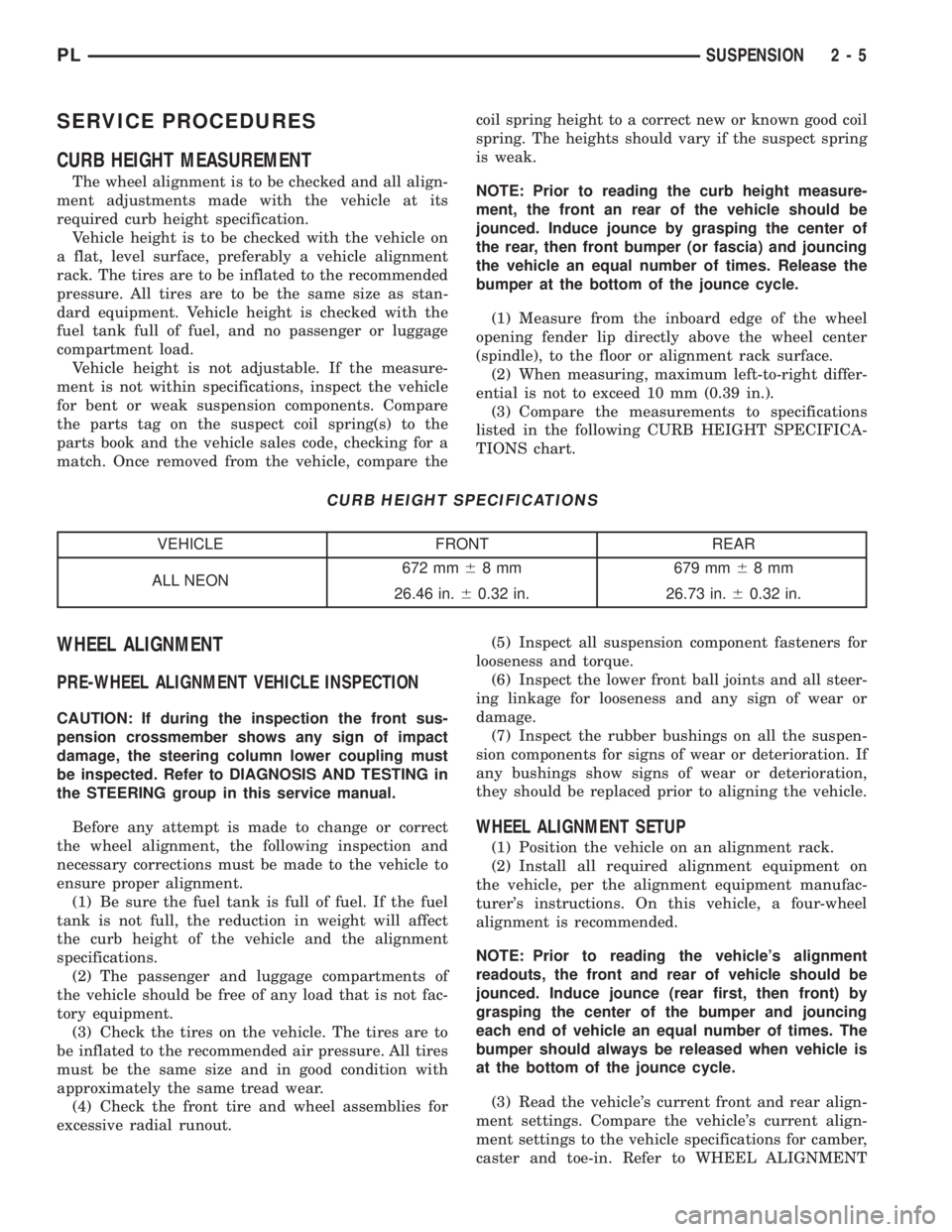
CURB HEIGHT SPECIFICATIONS
VEHICLE FRONT REAR
ALL NEON672 mm68 mm 679 mm68mm
26.46 in.60.32 in. 26.73 in.60.32 in.
WHEEL ALIGNMENT
PRE-WHEEL ALIGNMENT VEHICLE INSPECTION
CAUTION: If during the inspection the front sus-
pension crossmember shows any sign of impact
damage, the steering column lower coupling must
be inspected. Refer to DIAGNOSIS AND TESTING in
the STEERING group in this service manual.
Before any attempt is made to change or correct
the wheel alignment, the following inspection and
necessary corrections must be made to the vehicle to
ensure proper alignment.
(1) Be sure the fuel tank is full of fuel. If the fuel
tank is not full, the reduction in weight will affect
the curb height of the vehicle and the alignment
specifications.
(2) The passenger and luggage compartments of
the vehicle should be free of any load that is not fac-
tory equipment.
(3) Check the tires on the vehicle. The tires are to
be inflated to the recommended air pressure. All tires
must be the same size and in good condition with
approximately the same tread wear.
(4) Check the front tire and wheel assemblies for
excessive radial runout.(5) Inspect all suspension component fasteners for
looseness and torque.
(6) Inspect the lower front ball joints and all steer-
ing linkage for looseness and any sign of wear or
damage.
(7) Inspect the rubber bushings on all the suspen-
sion components for signs of wear or deterioration. If
any bushings show signs of wear or deterioration,
they should be replaced prior to aligning the vehicle.
WHEEL ALIGNMENT SETUP
(1) Position the vehicle on an alignment rack.
(2) Install all required alignment equipment on
the vehicle, per the alignment equipment manufac-
turer's instructions. On this vehicle, a four-wheel
alignment is recommended.
NOTE: Prior to reading the vehicle's alignment
readouts, the front and rear of vehicle should be
jounced. Induce jounce (rear first, then front) by
grasping the center of the bumper and jouncing
each end of vehicle an equal number of times. The
bumper should always be released when vehicle is
at the bottom of the jounce cycle.
(3) Read the vehicle's current front and rear align-
ment settings. Compare the vehicle's current align-
ment settings to the vehicle specifications for camber,
caster and toe-in. Refer to WHEEL ALIGNMENT
PLSUSPENSION 2 - 5
Page 24 of 1285
STEERING KNUCKLE
The front suspension steering knuckle is not a
repairable component of the front suspension. It
must be replaced if found to be damaged in any way.
If it is determined that the steering knuckle is bent
when servicing the vehicle, no attempt is to be made
to straighten the steering knuckle.
WHEEL BEARING AND HUB
The wheel bearing is designed for the life of the
vehicle and requires no type of periodic maintenance.
The following procedure may be used for diagnosing
the condition of the wheel bearing and hub.
With the wheel, disc brake caliper, and brake rotor
removed, rotate the wheel hub. Any roughness or
resistance to rotation may indicate dirt intrusion or a
failed hub bearing. If the bearing exhibits any of
these conditions during diagnosis, the hub bearing
will require replacement. The bearing is not service-
able.Damaged bearing seals and the resulting excessive
grease loss may also require bearing replacement.
Moderate grease weapage from the bearing is consid-
ered normal and should not require replacement of
the wheel bearing.
To diagnose a bent hub, refer to BRAKE ROTOR in
the DIAGNOSIS AND TESTING section in the
BRAKES service manual group for the procedure on
measuring hub runout.
LOWER CONTROL ARM
Inspect the lower control arm for signs of damage
from contact with the ground or road debris. If the
lower control arm shows any sign of damage, look for
distortion. Do not attempt to repair or straighten a
broken or bent lower control arm. If damaged, the
lower control arm stamping is serviced only as a
complete component.
The serviceable components of the lower control
arm are: the ball joint, the ball joint grease seal and
the lower control arm rear isolator bushing.
Inspect both lower control arm isolator bushings
for severe deterioration and replace as required.
Inspect the ball joint per the inspection procedure in
this section of the service manual and replace as
required. Refer to BALL JOINT in this section of this
service manual group.
BALL JOINT
With the weight of the vehicle resting on the road
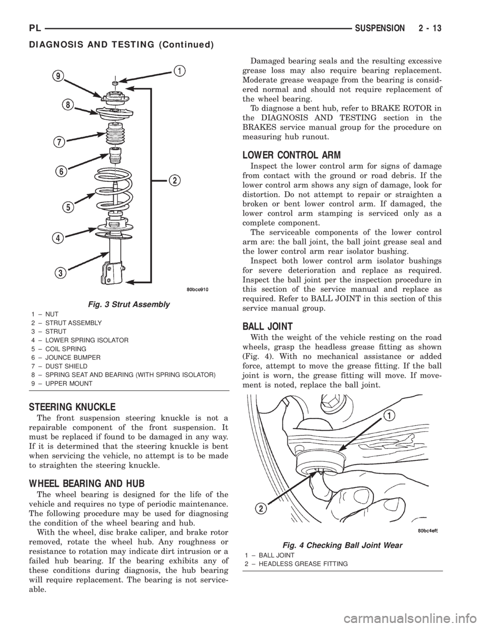
wheels, grasp the headless grease fitting as shown
(Fig. 4). With no mechanical assistance or added
force, attempt to move the grease fitting. If the ball
joint is worn, the grease fitting will move. If move-
ment is noted, replace the ball joint.
Fig. 3 Strut Assembly
1 ± NUT
2 ± STRUT ASSEMBLY
3 ± STRUT
4 ± LOWER SPRING ISOLATOR
5 ± COIL SPRING
6 ± JOUNCE BUMPER
7 ± DUST SHIELD
8 ± SPRING SEAT AND BEARING (WITH SPRING ISOLATOR)
9 ± UPPER MOUNT
Fig. 4 Checking Ball Joint Wear
1 ± BALL JOINT
2 ± HEADLESS GREASE FITTING
PLSUSPENSION 2 - 13
DIAGNOSIS AND TESTING (Continued)
Page 50 of 1285
KNUCKLE (REAR)
The rear knuckle is not a repairable component of
the rear suspension. Upon visual inspection, if it is
determined that the knuckle is cracked, bent or bro-
ken, no attempt is to be made to repair or to
straighten the knuckle. The knuckle must be
replaced if found to be damaged in any way.
HUB AND BEARING (REAR)
The hub and bearing is designed for the life of the
vehicle and requires no type of periodic maintenance
(Fig. 1). The following procedure may be used for
diagnosing the condition of the hub and bearing.
With the wheel, disc brake rotor or brake drum
removed, rotate the hub. Any roughness or resistance
to rotation may indicate dirt intrusion or a failed hub
bearing. If the bearing exhibits any of these condi-
tions during diagnosis, the hub and bearing will
require replacement. The bearing is not serviceable
alone.
Damaged bearing seals and the resulting excessive
grease loss may also require hub and bearing
replacement. Moderate grease weapage from thebearing is considered normal and should not require
replacement of the wheel bearing.
To diagnose a bent hub, refer to BRAKE ROTOR in
the DIAGNOSIS AND TESTING section in the
BRAKES service manual group for the procedure on
measuring hub runout.
LATERAL ARMS
Inspect each lateral arm (Fig. 1). Look for signs of
contact with an object that has caused damage to the
lateral arm. If the lateral arm is bent or damaged,
the lateral arm will require replacement. Do not
attempt to repair or straighten a lateral arm.
Inspect the lateral arm isolator bushings and their
sleeves for signs of damage or deterioration. If dam-
age or deterioration is present, replacement of the
entire lateral arm will be required. The isolator
bushings cannot be serviced separately from the lat-
eral arms.
TENSION STRUT
Inspect the tension strut (Fig. 1). Look for signs of
contact with any object that has bent or caused other
damage to the tension strut. If the tension strut is
bent or damaged, the tension strut will require
replacement. Do not attempt to repair or straighten a
tension strut.
Inspect the tension strut front (spool type) bushing,
and rear (bayonet type) bushings and retainers for
signs of deterioration or damage. If the front bushing
is damaged or shows signs of deteriation, the tension
strut must be replaced. The front bushing cannot be
replaced separately. If the rear bushings are deterio-
rated or damaged, or the retainers are damaged,
replacement is necessary. The bushings and retainers
can be replaced separately from the tension strut.
STABILIZER BAR (REAR)
Inspect the stabilizer bar (Fig. 1). Look for damage
or bending. If damage is evident, the bar must be
replaced.
Inspect for broken, cracked or distorted stabilizer
bar cushions and cushion retainers. The horizontal
slit at the front of each cushion is supposed to be
there. If damage is evident, the cushions can be
replaced separately from the stabilizer bar utilizing
the horizontal slit.
Inspect the stabilizer bar links that attach the sta-
bilizer bar to each rear strut. Look for damage or
deterioration of the bushings on the ends of each
link. Inspect the stabilizer bar link to ensure it is not
bent or broken. If any of these conditions are present,
the stabilizer bar link must be replaced. The links
can be replaced separately from the stabilizer bar.
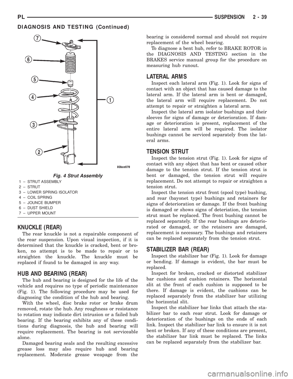
Fig. 4 Strut Assembly
1 ± STRUT ASSEMBLY
2 ± STRUT
3 ± LOWER SPRING ISOLATOR
4 ± COIL SPRING
5 ± JOUNCE BUMPER
6 ± DUST SHIELD
7 ± UPPER MOUNT
PLSUSPENSION 2 - 39
DIAGNOSIS AND TESTING (Continued)
Page 88 of 1285
DIAGNOSIS AND TESTING
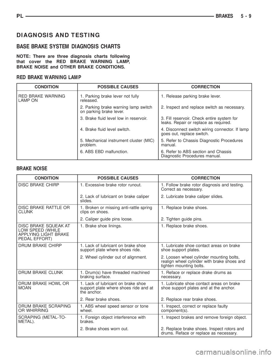
BASE BRAKE SYSTEM DIAGNOSIS CHARTS
NOTE: There are three diagnosis charts following
that cover the RED BRAKE WARNING LAMP,
BRAKE NOISE and OTHER BRAKE CONDITIONS.
RED BRAKE WARNING LAMP
CONDITION POSSIBLE CAUSES CORRECTION
RED BRAKE WARNING
LAMP ON1. Parking brake lever not fully
released.1. Release parking brake lever.
2. Parking brake warning lamp switch
on parking brake lever.2. Inspect and replace switch as necessary.
3. Brake fluid level low in reservoir. 3. Fill reservoir. Check entire system for
leaks. Repair or replace as required.
4. Brake fluid level switch. 4. Disconnect switch wiring connector. If lamp
goes out, replace switch.
5. Mechanical instrument cluster (MIC)
problem.5. Refer to Chassis Diagnostic Procedures
manual.
6. ABS EBD malfunction. 6. Refer to ABS section and Chassis
Diagnostic Procedures manual.
BRAKE NOISE
CONDITION POSSIBLE CAUSES CORRECTION
DISC BRAKE CHIRP 1. Excessive brake rotor runout. 1. Follow brake rotor diagnosis and testing.
Correct as necessary.
2. Lack of lubricant on brake caliper
slides.2. Lubricate brake caliper slides.
DISC BRAKE RATTLE OR
CLUNK1. Broken or missing anti-rattle spring
clips on shoes.1. Replace brake shoes.
2. Caliper guide pins loose. 2. Tighten guide pins.
DISC BRAKE SQUEAK AT
LOW SPEED (WHILE
APPLYING LIGHT BRAKE
PEDAL EFFORT)1. Brake shoe linings. 1. Replace brake shoes.
DRUM BRAKE CHIRP 1. Lack of lubricant on brake shoe
support plate where shoes ride.1. Lubricate shoe contact areas on brake
shoe support plates.
2. Wheel cylinder out of alignment. 2. Loosen wheel cylinder mounting bolts,
realign wheel cylinder with brake shoes and
tighten mounting bolts.
DRUM BRAKE CLUNK 1. Drum(s) have threaded machined
braking surface.1. Reface or replace drake drums as
necessary.
DRUM BRAKE HOWL OR
MOAN1. Lack of lubricant on brake shoe
support plate where shoes ride and at
the anchor.1. Lubricate shoe contact areas on brake
shoe support plates and at the anchor.
2. Rear brake shoes. 2. Replace rear brake shoes.
DRUM BRAKE SCRAPING
OR WHIRRING1. ABS wheel speed sensor or tone
wheel.1. Inspect, correct or replace faulty
component(s).
SCRAPING (METAL-TO-
METAL).1. Foreign object interference with
brakes.1. Inspect brakes and remove foreign object.
2. Brake shoes worn out. 2. Replace brake shoes. Inspect rotors and
drums. Reface or replace as necessary.
PLBRAKES 5 - 9
Page 89 of 1285
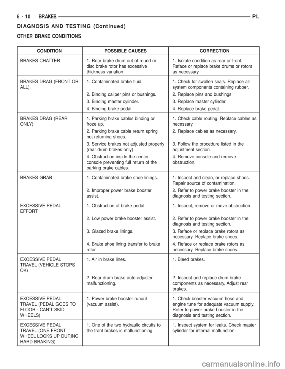
OTHER BRAKE CONDITIONS
CONDITION POSSIBLE CAUSES CORRECTION
BRAKES CHATTER 1. Rear brake drum out of round or
disc brake rotor has excessive
thickness variation.1. Isolate condition as rear or front.
Reface or replace brake drums or rotors
as necessary.
BRAKES DRAG (FRONT OR
ALL)1. Contaminated brake fluid. 1. Check for swollen seals. Replace all
system components containing rubber.
2. Binding caliper pins or bushings. 2. Replace pins and bushings
3. Binding master cylinder. 3. Replace master cylinder.
4. Binding brake pedal. 4. Replace brake pedal.
BRAKES DRAG (REAR
ONLY)1. Parking brake cables binding or
froze up.1. Check cable routing. Replace cables as
necessary.
2. Parking brake cable return spring
not returning shoes.2. Replace cables as necessary.
3. Service brakes not adjusted properly
(rear drum brakes only).3. Follow the procedure listed in the
adjustment section.
4. Obstruction inside the center
console preventing full return of the
parking brake cables.4. Remove console and remove
obstruction.
BRAKES GRAB 1. Contaminated brake shoe linings. 1. Inspect and clean, or replace shoes.
Repair source of contamination.
2. Improper power brake booster
assist.2. Refer to power brake booster in the
diagnosis and testing section.
EXCESSIVE PEDAL
EFFORT1. Obstruction of brake pedal. 1. Inspect, remove or move obstruction.
2. Low power brake booster assist. 2. Refer to power brake booster in the
diagnosis and testing section.
3. Glazed brake linings. 3. Reface or replace brake rotors as
necessary. Replace brake shoes.
4. Brake shoe lining transfer to brake
rotor.4. Reface or replace brake rotors as
necessary. Replace brake shoes.
EXCESSIVE PEDAL
TRAVEL (VEHICLE STOPS
OK)1. Air in brake lines. 1. Bleed brakes.
2. Rear drum brake auto-adjuster
malfunctioning.2. Inspect and replace drum brake
components as necessary. Adjust rear
brakes.
EXCESSIVE PEDAL
TRAVEL (PEDAL GOES TO
FLOOR - CAN'T SKID
WHEELS)1. Power brake booster runout
(vacuum assist).1. Check booster vacuum hose and
engine tune for adequate vacuum supply.
Refer to power brake booster in the
diagnosis and testing section.
EXCESSIVE PEDAL
TRAVEL (ONE FRONT
WHEEL LOCKS UP DURING
HARD BRAKING)1. One of the two hydraulic circuits to
the front brakes is malfunctioning.1. Inspect system for leaks. Check master
cylinder for internal malfunction.
5 - 10 BRAKESPL
DIAGNOSIS AND TESTING (Continued)
Page 90 of 1285
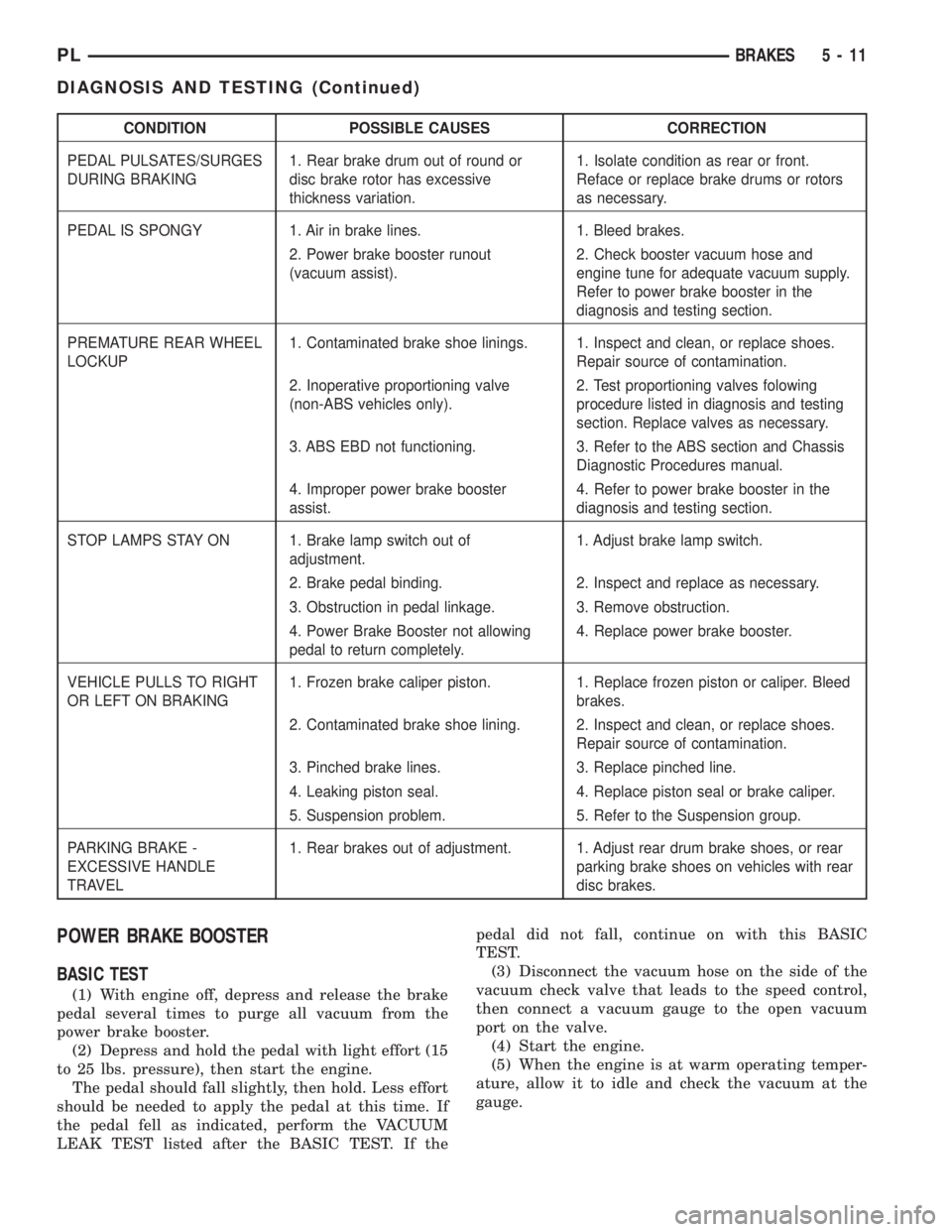
CONDITION POSSIBLE CAUSES CORRECTION
PEDAL PULSATES/SURGES
DURING BRAKING1. Rear brake drum out of round or
disc brake rotor has excessive
thickness variation.1. Isolate condition as rear or front.
Reface or replace brake drums or rotors
as necessary.
PEDAL IS SPONGY 1. Air in brake lines. 1. Bleed brakes.
2. Power brake booster runout
(vacuum assist).2. Check booster vacuum hose and
engine tune for adequate vacuum supply.
Refer to power brake booster in the
diagnosis and testing section.
PREMATURE REAR WHEEL
LOCKUP1. Contaminated brake shoe linings. 1. Inspect and clean, or replace shoes.
Repair source of contamination.
2. Inoperative proportioning valve
(non-ABS vehicles only).2. Test proportioning valves folowing
procedure listed in diagnosis and testing
section. Replace valves as necessary.
3. ABS EBD not functioning. 3. Refer to the ABS section and Chassis
Diagnostic Procedures manual.
4. Improper power brake booster
assist.4. Refer to power brake booster in the
diagnosis and testing section.
STOP LAMPS STAY ON 1. Brake lamp switch out of
adjustment.1. Adjust brake lamp switch.
2. Brake pedal binding. 2. Inspect and replace as necessary.
3. Obstruction in pedal linkage. 3. Remove obstruction.
4. Power Brake Booster not allowing
pedal to return completely.4. Replace power brake booster.
VEHICLE PULLS TO RIGHT
OR LEFT ON BRAKING1. Frozen brake caliper piston. 1. Replace frozen piston or caliper. Bleed
brakes.
2. Contaminated brake shoe lining. 2. Inspect and clean, or replace shoes.
Repair source of contamination.
3. Pinched brake lines. 3. Replace pinched line.
4. Leaking piston seal. 4. Replace piston seal or brake caliper.
5. Suspension problem. 5. Refer to the Suspension group.
PARKING BRAKE -
EXCESSIVE HANDLE
TRAVEL1. Rear brakes out of adjustment. 1. Adjust rear drum brake shoes, or rear
parking brake shoes on vehicles with rear
disc brakes.
POWER BRAKE BOOSTER
BASIC TEST
(1) With engine off, depress and release the brake
pedal several times to purge all vacuum from the
power brake booster.
(2) Depress and hold the pedal with light effort (15
to 25 lbs. pressure), then start the engine.
The pedal should fall slightly, then hold. Less effort
should be needed to apply the pedal at this time. If
the pedal fell as indicated, perform the VACUUM
LEAK TEST listed after the BASIC TEST. If thepedal did not fall, continue on with this BASIC
TEST.
(3) Disconnect the vacuum hose on the side of the
vacuum check valve that leads to the speed control,
then connect a vacuum gauge to the open vacuum
port on the valve.
(4) Start the engine.
(5) When the engine is at warm operating temper-
ature, allow it to idle and check the vacuum at the
gauge.
PLBRAKES 5 - 11
DIAGNOSIS AND TESTING (Continued)