2000 DODGE NEON auto shift cable
[x] Cancel search: auto shift cablePage 101 of 1285
BRAKE ROTOR LIMITS
Braking Rotor Rotor ThicknessMinimum
Rotor
ThicknessRotor
Thickness
VariationRotor Run
Out*Rotor Micro
Finish
Front Rotor21.87±22.13 mm
0.861-0.871 in.20.4 mm
0.803 in.0.013 mm
0.0005 in.0.08 mm
0.003 in.15-80 RMS
Rear Rotor8.75±9.25 mm
0.344 -0.364 in.7.25 mm
0.285 in.0.013 mm
0.0005 in.0.08 mm
0.003 in.15-80 RMS
* TIR Total Indicator Reading (Measured On Vehicle)
BRAKE DRUM MACHINING
If a brake drum is deeply scored or warped, it can
be machined on a brake lathe equipped to machine
brake drums. Follow the manufacturers instructions
on the machining procedure.
Measure the brake drum diameter before machin-
ing. If machining the drum will cause the drum to
exceed maximum allowable diameter, do not machine
the brake drum. It needs to be replaced.
CAUTION: Do not machine the brake drum if it will
cause the drum to exceed maximum allowable
diameter.
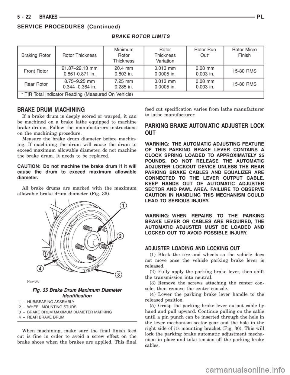
All brake drums are marked with the maximum
allowable brake drum diameter (Fig. 35).
When machining, make sure the final finish feed
cut is fine in order to avoid a screw effect on the
brake shoes when the brakes are applied. This finalfeed cut specification varies from lathe manufacturer
to lathe manufacturer.
PARKING BRAKE AUTOMATIC ADJUSTER LOCK
OUT
WARNING: THE AUTOMATIC ADJUSTING FEATURE
OF THIS PARKING BRAKE LEVER CONTAINS A
CLOCK SPRING LOADED TO APPROXIMATELY 25
POUNDS. DO NOT RELEASE THE AUTOMATIC
ADJUSTER LOCKOUT DEVICE UNLESS THE REAR
PARKING BRAKE CABLES AND EQUALIZER ARE
CONNECTED TO THE LEVER OUTPUT CABLE.
KEEP HANDS OUT OF AUTOMATIC ADJUSTER
SECTOR AND PAWL AREA. FAILURE TO OBSERVE
CAUTION IN HANDLING THIS MECHANISM COULD
LEAD TO SERIOUS INJURY.
WARNING: WHEN REPAIRS TO THE PARKING
BRAKE LEVER OR CABLES ARE REQUIRED, THE
AUTOMATIC ADJUSTER MUST BE LOADED AND
LOCKED OUT TO AVOID POSSIBLE INJURY.
ADJUSTER LOADING AND LOCKING OUT
(1) Block the tire and wheels so the vehicle does
not move once the vehicle parking brake lever is
released.
(2) Fully apply the parking brake lever, then shift
the transmission into neutral.
(3) Remove the screws attaching the center con-
sole, then remove the center console.
(4) Lower the parking brake lever handle to the
released position.
(5) Grasp the parking brake lever output cable by
hand and pull upward. Continue pulling on the cable
until a pin punch can be inserted through the hole in
the lever mechanism sector gear and the hole in the
right side of its mounting bracket (Fig. 36). This will
lock the parking brake automatic adjustment mecha-
nism in place and take tension off the parking brake
cables.
Fig. 35 Brake Drum Maximum Diameter
Identification
1 ± HUB/BEARING ASSEMBLY
2 ± WHEEL MOUNTING STUDS
3 ± BRAKE DRUM MAXIMUM DIAMETER MARKING
4 ± REAR BRAKE DRUM
5 - 22 BRAKESPL
SERVICE PROCEDURES (Continued)
Page 127 of 1285
PARKING BRAKE LEVER
WARNING: THE AUTOMATIC ADJUSTING FEATURE
OF THIS PARKING BRAKE LEVER CONTAINS A
CLOCK SPRING LOADED TO APPROXIMATELY 25
POUNDS. DO NOT RELEASE THE AUTOMATIC
ADJUSTER LOCKOUT DEVICE UNLESS THE REAR
PARKING BRAKE CABLES AND EQUALIZER ARE
CONNECTED TO THE LEVER OUTPUT CABLE.
KEEP HANDS OUT OF AUTOMATIC ADJUSTER
SECTOR AND PAWL AREA. FAILURE TO OBSERVE
CAUTION IN HANDLING THIS MECHANISM COULD
LEAD TO SERIOUS INJURY.
WARNING: WHEN REPAIRS TO THE PARKING
BRAKE LEVER OR CABLES ARE REQUIRED, THE
AUTOMATIC ADJUSTER MUST BE LOADED AND
LOCKED OUT TO AVOID POSSIBLE INJURY. THE
LEVER ADJUSTMENT MECHANISM CAN BE
LOADED AND LOCKED OUT AS OUTLINED IN THIS
PROCEDURE.
REMOVAL
(1) Block the tire and wheels so the vehicle does
not move once the vehicle parking brake lever is
released.
(2) Fully apply the parking brake lever, then shift
the transmission into neutral.
(3) Remove the screws attaching the center con-
sole, then remove the center console.
(4) Lower the parking brake lever handle to the
released position.
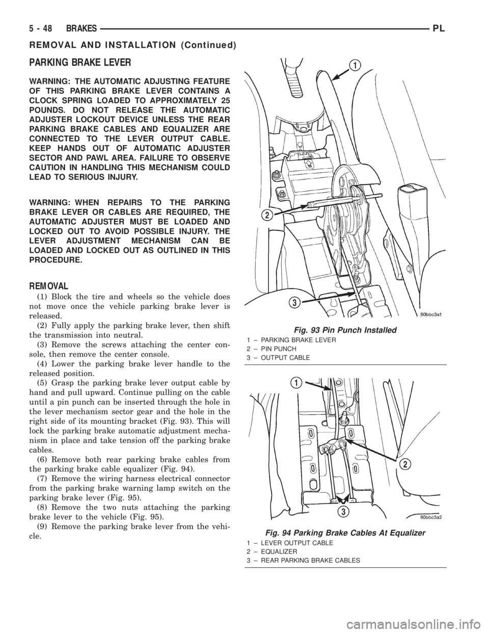
(5) Grasp the parking brake lever output cable by
hand and pull upward. Continue pulling on the cable
until a pin punch can be inserted through the hole in
the lever mechanism sector gear and the hole in the
right side of its mounting bracket (Fig. 93). This will
lock the parking brake automatic adjustment mecha-
nism in place and take tension off the parking brake
cables.
(6) Remove both rear parking brake cables from
the parking brake cable equalizer (Fig. 94).
(7) Remove the wiring harness electrical connector
from the parking brake warning lamp switch on the
parking brake lever (Fig. 95).
(8) Remove the two nuts attaching the parking
brake lever to the vehicle (Fig. 95).
(9) Remove the parking brake lever from the vehi-
cle.
Fig. 93 Pin Punch Installed
1 ± PARKING BRAKE LEVER
2 ± PIN PUNCH
3 ± OUTPUT CABLE
Fig. 94 Parking Brake Cables At Equalizer
1 ± LEVER OUTPUT CABLE
2 ± EQUALIZER
3 ± REAR PARKING BRAKE CABLES
5 - 48 BRAKESPL
REMOVAL AND INSTALLATION (Continued)
Page 128 of 1285
INSTALLATION
(1) Place the parking brake lever on the mounting
studs on the vehicle floor. Install and tighten the two
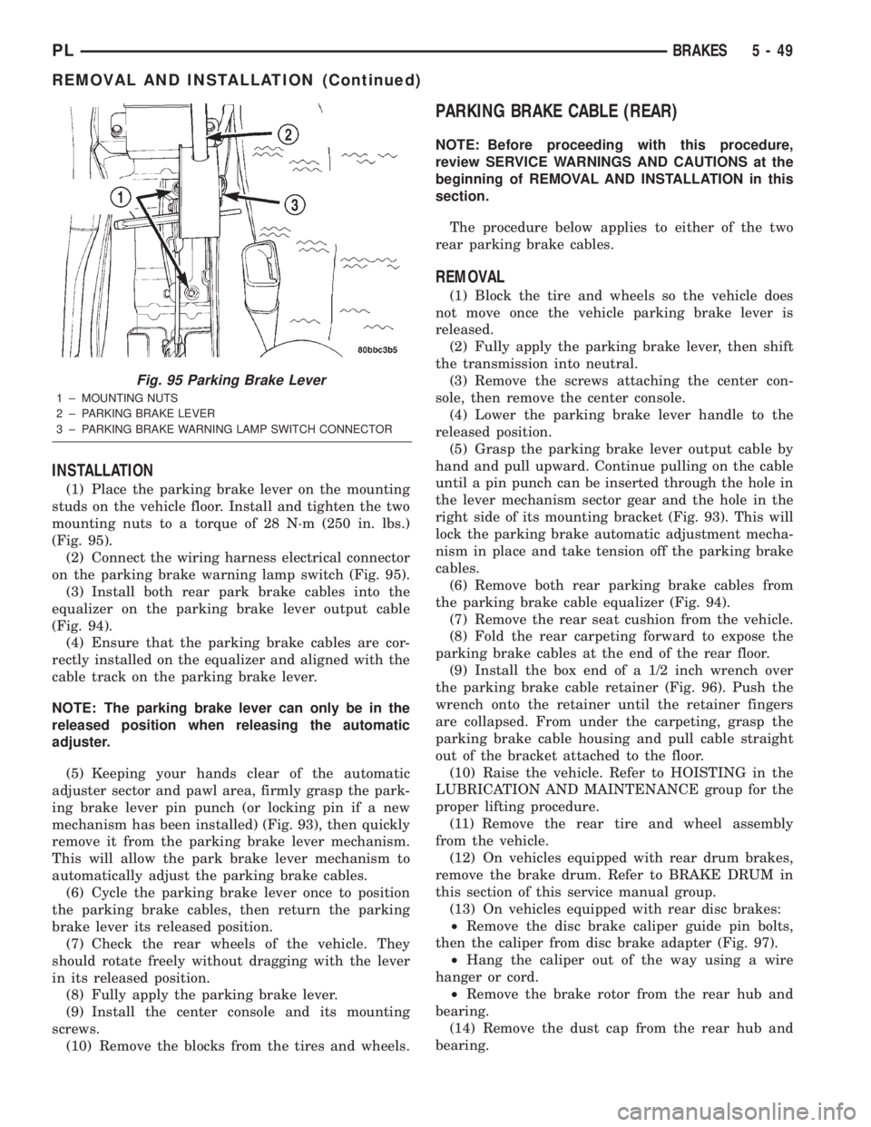
mounting nuts to a torque of 28 N´m (250 in. lbs.)
(Fig. 95).
(2) Connect the wiring harness electrical connector
on the parking brake warning lamp switch (Fig. 95).
(3) Install both rear park brake cables into the
equalizer on the parking brake lever output cable
(Fig. 94).
(4) Ensure that the parking brake cables are cor-
rectly installed on the equalizer and aligned with the
cable track on the parking brake lever.
NOTE: The parking brake lever can only be in the
released position when releasing the automatic
adjuster.
(5) Keeping your hands clear of the automatic
adjuster sector and pawl area, firmly grasp the park-
ing brake lever pin punch (or locking pin if a new
mechanism has been installed) (Fig. 93), then quickly
remove it from the parking brake lever mechanism.
This will allow the park brake lever mechanism to
automatically adjust the parking brake cables.
(6) Cycle the parking brake lever once to position
the parking brake cables, then return the parking
brake lever its released position.
(7) Check the rear wheels of the vehicle. They
should rotate freely without dragging with the lever
in its released position.
(8) Fully apply the parking brake lever.
(9) Install the center console and its mounting
screws.
(10) Remove the blocks from the tires and wheels.
PARKING BRAKE CABLE (REAR)
NOTE: Before proceeding with this procedure,
review SERVICE WARNINGS AND CAUTIONS at the
beginning of REMOVAL AND INSTALLATION in this
section.
The procedure below applies to either of the two
rear parking brake cables.
REMOVAL
(1) Block the tire and wheels so the vehicle does
not move once the vehicle parking brake lever is
released.
(2) Fully apply the parking brake lever, then shift
the transmission into neutral.
(3) Remove the screws attaching the center con-
sole, then remove the center console.
(4) Lower the parking brake lever handle to the
released position.
(5) Grasp the parking brake lever output cable by
hand and pull upward. Continue pulling on the cable
until a pin punch can be inserted through the hole in
the lever mechanism sector gear and the hole in the
right side of its mounting bracket (Fig. 93). This will
lock the parking brake automatic adjustment mecha-
nism in place and take tension off the parking brake
cables.
(6) Remove both rear parking brake cables from
the parking brake cable equalizer (Fig. 94).
(7) Remove the rear seat cushion from the vehicle.
(8) Fold the rear carpeting forward to expose the
parking brake cables at the end of the rear floor.
(9) Install the box end of a 1/2 inch wrench over
the parking brake cable retainer (Fig. 96). Push the
wrench onto the retainer until the retainer fingers
are collapsed. From under the carpeting, grasp the
parking brake cable housing and pull cable straight
out of the bracket attached to the floor.
(10) Raise the vehicle. Refer to HOISTING in the
LUBRICATION AND MAINTENANCE group for the
proper lifting procedure.
(11) Remove the rear tire and wheel assembly
from the vehicle.
(12) On vehicles equipped with rear drum brakes,
remove the brake drum. Refer to BRAKE DRUM in
this section of this service manual group.
(13) On vehicles equipped with rear disc brakes:
²Remove the disc brake caliper guide pin bolts,
then the caliper from disc brake adapter (Fig. 97).
²Hang the caliper out of the way using a wire
hanger or cord.
²Remove the brake rotor from the rear hub and
bearing.
(14) Remove the dust cap from the rear hub and
bearing.
Fig. 95 Parking Brake Lever
1 ± MOUNTING NUTS
2 ± PARKING BRAKE LEVER
3 ± PARKING BRAKE WARNING LAMP SWITCH CONNECTOR
PLBRAKES 5 - 49
REMOVAL AND INSTALLATION (Continued)
Page 226 of 1285
FEED CIRCUIT
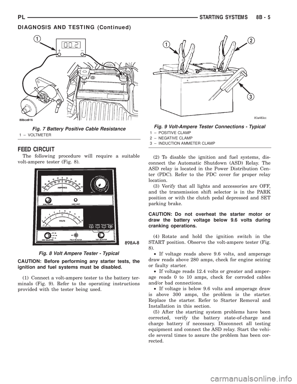
The following procedure will require a suitable
volt-ampere tester (Fig. 8).
CAUTION: Before performing any starter tests, the
ignition and fuel systems must be disabled.
(1) Connect a volt-ampere tester to the battery ter-
minals (Fig. 9). Refer to the operating instructions
provided with the tester being used.(2) To disable the ignition and fuel systems, dis-
connect the Automatic Shutdown (ASD) Relay. The
ASD relay is located in the Power Distribution Cen-
ter (PDC). Refer to the PDC cover for proper relay
location.
(3) Verify that all lights and accessories are OFF,
and the transmission shift selector is in the PARK
position or with the clutch pedal depressed and SET
parking brake.
CAUTION: Do not overheat the starter motor or
draw the battery voltage below 9.6 volts during
cranking operations.
(4) Rotate and hold the ignition switch in the
START position. Observe the volt-ampere tester (Fig.
8).
²If voltage reads above 9.6 volts, and amperage
draw reads above 280 amps, check for engine seizing
or faulty starter.
²If voltage reads 12.4 volts or greater and amper-
age reads 0 to 10 amps, check for corroded cables
and/or bad connections.
²If voltage is below 9.6 volts and amperage draw
is above 300 amps, the problem is the starter.
Replace the starter. Refer to Starter Removal and
Installation in this section.
(5) After the starting system problems have been
corrected, verify the battery state-of-charge and
charge battery if necessary. Disconnect all testing
equipment and connect the ASD relay. Start the vehi-
cle several times to assure the problem has been cor-
rected.
Fig. 7 Battery Positive Cable Resistance
1 ± VOLTMETER
Fig. 8 Volt Ampere Tester - Typical
Fig. 9 Volt-Ampere Tester Connections - Typical
1 ± POSITIVE CLAMP
2 ± NEGATIVE CLAMP
3 ± INDUCTION AMMETER CLAMP
PLSTARTING SYSTEMS 8B - 5
DIAGNOSIS AND TESTING (Continued)
Page 241 of 1285
IGNITION INTERLOCK
OPERATION
All vehicles equipped with automatic transaxles
have an interlock system. The system prevents shift-
ing the vehicle out of Park unless the ignition lock
cylinder is in the Off, Run or Start position. In addi-
tion, the operator cannot rotate the key to the lock
position unless the shifter is in the park position. On
vehicles equipped with floor shift refer to the - Tran-
saxle for Automatic Transmission Shifter/Ignition
Interlock.
REMOVAL AND INSTALLATION
SPARK PLUG SERVICE
Failure to route the cables properly could cause the
radio to reproduce ignition noise, cross ignition of the
spark plugs or short circuit the cables to ground.
REMOVAL
REMOVE CABLES FROM COIL FIRST.
Always remove the spark plug cable by grasping
the top of the spark plug insulator, turning the boot
1/2 turn and pulling straight up in a steady motion.
(1) Remove the spark plug using a quality socket
with a rubber or foam insert.
(2) Inspect the spark plug condition.
INSTALLATION
(1) To avoid cross threading, start the spark plug
into the cylinder head by hand.
(2) Tighten spark plugs to 28 N´m (20 ft. lbs.)
torque.
(3) Install spark plug insulators over spark plugs.
Ensure the top of the spark plug insulator covers the
upper end of the spark plug tube.
Reconnect to coil.
SPARK PLUG CABLE SERVICE
Failure to route the cables properly could cause the
radio to reproduce ignition noise, cross ignition of the
spark plugs or short circuit the cables to ground.
REMOVAL
Remove spark plug cable from coil first.
Always remove the spark plug cable by grasping
the top of the spark plug insulator, turning the boot
1/2 turn and pulling straight up in a steady motion.
INSTALLATION
Install spark plug insulators over spark plugs.
Ensure the top of the spark plug insulator covers the
upper end of the spark plug tube. The connect theother end to coil pack. Be sure that dual plastic clip
holds the cables off of the valve cover.
IGNITION COIL
The electronic ignition coil pack attaches directly
to the valve cover (Fig. 11).
REMOVAL
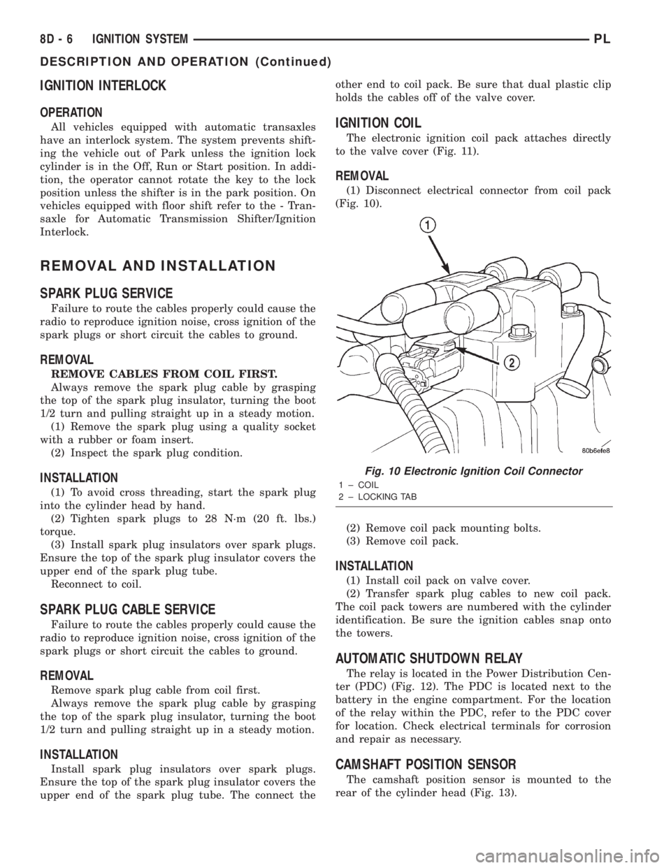
(1) Disconnect electrical connector from coil pack
(Fig. 10).
(2) Remove coil pack mounting bolts.
(3) Remove coil pack.
INSTALLATION
(1) Install coil pack on valve cover.
(2) Transfer spark plug cables to new coil pack.
The coil pack towers are numbered with the cylinder
identification. Be sure the ignition cables snap onto
the towers.
AUTOMATIC SHUTDOWN RELAY
The relay is located in the Power Distribution Cen-
ter (PDC) (Fig. 12). The PDC is located next to the
battery in the engine compartment. For the location
of the relay within the PDC, refer to the PDC cover
for location. Check electrical terminals for corrosion
and repair as necessary.
CAMSHAFT POSITION SENSOR
The camshaft position sensor is mounted to the
rear of the cylinder head (Fig. 13).
Fig. 10 Electronic Ignition Coil Connector
1 ± COIL
2 ± LOCKING TAB
8D - 6 IGNITION SYSTEMPL
DESCRIPTION AND OPERATION (Continued)
Page 263 of 1285
(1) Disconnect the negative battery cable.
(2) Remove the floor console. Refer to Group 23,
Body for the procedure.
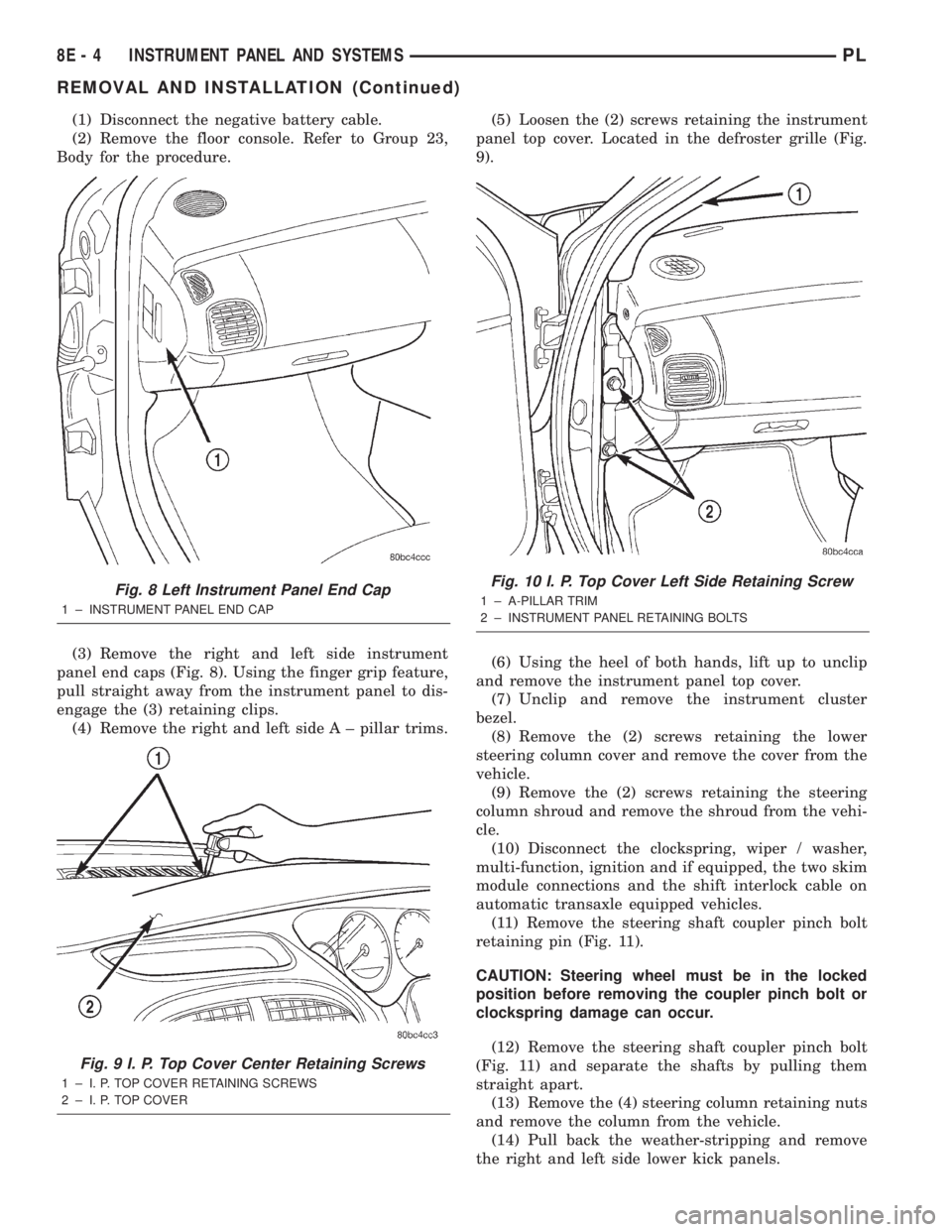
(3) Remove the right and left side instrument
panel end caps (Fig. 8). Using the finger grip feature,
pull straight away from the instrument panel to dis-
engage the (3) retaining clips.
(4) Remove the right and left side A ± pillar trims.(5) Loosen the (2) screws retaining the instrument
panel top cover. Located in the defroster grille (Fig.
9).
(6) Using the heel of both hands, lift up to unclip
and remove the instrument panel top cover.
(7) Unclip and remove the instrument cluster
bezel.
(8) Remove the (2) screws retaining the lower
steering column cover and remove the cover from the
vehicle.
(9) Remove the (2) screws retaining the steering
column shroud and remove the shroud from the vehi-
cle.
(10) Disconnect the clockspring, wiper / washer,
multi-function, ignition and if equipped, the two skim
module connections and the shift interlock cable on
automatic transaxle equipped vehicles.
(11) Remove the steering shaft coupler pinch bolt
retaining pin (Fig. 11).
CAUTION: Steering wheel must be in the locked
position before removing the coupler pinch bolt or
clockspring damage can occur.
(12) Remove the steering shaft coupler pinch bolt
(Fig. 11) and separate the shafts by pulling them
straight apart.
(13) Remove the (4) steering column retaining nuts
and remove the column from the vehicle.
(14) Pull back the weather-stripping and remove
the right and left side lower kick panels.
Fig. 8 Left Instrument Panel End Cap
1 ± INSTRUMENT PANEL END CAP
Fig. 9 I. P. Top Cover Center Retaining Screws
1 ± I. P. TOP COVER RETAINING SCREWS
2 ± I. P. TOP COVER
Fig. 10 I. P. Top Cover Left Side Retaining Screw
1 ± A-PILLAR TRIM
2 ± INSTRUMENT PANEL RETAINING BOLTS
8E - 4 INSTRUMENT PANEL AND SYSTEMSPL
REMOVAL AND INSTALLATION (Continued)
Page 267 of 1285
(17) Install the A/C outlet registers in the center
instrument bezel.
(18) Install the right and left side lower kick pan-
els. Reposition the weather-strip in its original posi-
tion.
(19) Install the steering column. Torque the retain-
ing nuts to 17 N´m (150 in. lbs.).
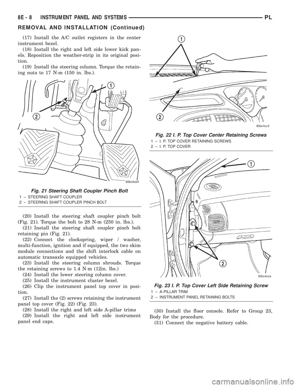
(20) Install the steering shaft coupler pinch bolt
(Fig. 21). Torque the bolt to 28 N´m (250 in. lbs.).
(21) Install the steering shaft coupler pinch bolt
retaining pin (Fig. 21).
(22) Connect the clockspring, wiper / washer,
multi-function, ignition and if equipped, the two skim
module connections and the shift interlock cable on
automatic transaxle equipped vehicles.
(23) Install the steering column shrouds. Torque
the retaining screws to 1.4 N´m (12in. lbs.)
(24) Install the lower steering column cover.
(25) Install the instrument cluster bezel.
(26) Clip the instrument panel top cover in posi-
tion.
(27) Install the (2) screws retaining the instrument
panel top cover (Fig. 22) (Fig. 23).
(28) Install the right and left side A-pillar trims
(29) Install the right and left side instrument
panel end caps.(30) Install the floor console. Refer to Group 23,
Body for the procedure.
(31) Connect the negative battery cable.
Fig. 21 Steering Shaft Coupler Pinch Bolt
1 ± STEERING SHAFT COUPLER
2 ± STEERING SHAFT COUPLER PINCH BOLT
Fig. 22 I. P. Top Cover Center Retaining Screws
1 ± I. P. TOP COVER RETAINING SCREWS
2 ± I. P. TOP COVER
Fig. 23 I. P. Top Cover Left Side Retaining Screw
1 ± A-PILLAR TRIM
2 ± INSTRUMENT PANEL RETAINING BOLTS
8E - 8 INSTRUMENT PANEL AND SYSTEMSPL
REMOVAL AND INSTALLATION (Continued)
Page 749 of 1285
(4) Discharge air conditioning system, if equipped.
Refer to Group 24, Heating and Air Conditioning for
procedure.
(5) Disconnect the following: air intake duct at
intake manifold, throttle cables, electrical connectors
from throttle body and air cleaner housing.
(6) Remove air cleaner housing assembly.
(7) Remove upper radiator hose and fan module.
Refer to Group 7, Cooling System for procedure.
(8) Remove lower radiator hose.
(9) Disconnect automatic transmission cooler lines
and plug, if equipped.
(10) Disconnect shift linkage, electrical connectors,
and clutch cable, if equipped with manual transaxle.
(11) Disconnect engine wiring harness.
(12) Disconnect positive cable from Power Distri-
bution Center (PDC) and ground wire from vehicle
body.
(13) Disconnect ground wire from the vehicle body-
to-engine at the right side strut tower.
(14) Disconnect heater hoses.
(15) Disconnect vacuum hose from brake booster.
(16) Disconnect coolant reserve/recovery hose.
(17) Remove accessory drive belts. Refer to Group
7, Cooling System for procedure.
(18) Remove power steering pump and reservoir
and set them aside.
(19) Hoist vehicle and remove right inner splash
shield.
(20) Drain engine oil.
(21) Remove front wheels.
(22) Remove axle shafts. Refer to Group 3, Differ-
ential and Driveline for procedure.
(23) Disconnect exhaust system from manifold.
(24) Disconnect the downstream oxygen sensor
connector.
(25) Remove lower engine torque strut.
(26) Remove structural collar. Refer to procedure
in this section.
(27) Lower vehicle and remove A/C compressor.
(28) Raise vehicle enough to allow engine dolly
and cradle, Special Tools 6135 and 6710 to be
installed under vehicle.
(29) Loosen engine support posts to allow move-
ment for positioning onto engine locating holes and
flange on the engine bedplate. Lower vehicle and
position cradle until the engine is resting on support
posts (Fig. 26). Tighten mounts to cradle frame. This
will keep support posts from moving when removing
or installing engine and transmission.
(30) Install safety straps around the engine to cra-
dle (Fig. 26). Tighten straps and lock them into posi-
tion.
WARNING: Safety straps MUST be used.(31) Raise vehicle enough to see if straps are tight
enough to hold cradle assembly to engine.
(32) Lower vehicle so weight of the engine and
transmission ONLY is on the cradle assembly.
(33) Remove the upper engine torque strut.
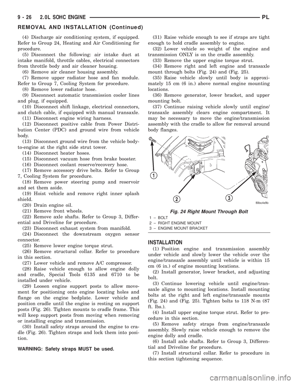
(34) Remove right and left engine and transaxle
mount through bolts (Fig. 24) and (Fig. 25).
(35) Raise vehicle slowly until body is approxi-
mately 15 cm (6 in.) above normal engine mounting
locations.
(36) Remove generator, lower bracket, and upper
mounting bolt.
(37) Continue raising vehicle slowly until engine/
transaxle assembly clears engine compartment. It
may be necessary to move the engine/transmission
assembly with the cradle to allow for removal around
body flanges.
INSTALLATION
(1) Position engine and transmission assembly
under vehicle and slowly lower the vehicle over the
engine/transaxle assembly until vehicle is within 15
cm (6 in.) of engine mounting locations.
(2) Install generator, lower bracket, and adjusting
bolt.
(3) Continue lowering vehicle until engine/tran-
saxle aligns to mounting locations. Install mounting
bolts at the right and left engine/transaxle mounts
(Fig. 24) and (Fig. 25). Tighten bolts to 118 N´m (87
ft. lbs.).
(4) Install upper engine torque strut. Refer to pro-
cedure in this section.
(5) Remove safety straps from engine/transaxle
assembly. Slowly raise vehicle enough to remove the
engine dolly and cradle.
(6) Install axle shafts. Refer to Group 3, Differen-
tial and Driveline for procedure.
(7) Install structural collar. Refer to procedure in
this section tightening sequence.
Fig. 24 Right Mount Through Bolt
1 ± BOLT
2 ± RIGHT ENGINE MOUNT
3 ± ENGINE MOUNT BRACKET
9 - 26 2.0L SOHC ENGINEPL
REMOVAL AND INSTALLATION (Continued)