2000 DODGE NEON auto shift cable
[x] Cancel search: auto shift cablePage 750 of 1285
(8) Install lower engine torque strut. Refer to pro-
cedure in this section.
(9) Connect exhaust system to manifold. Refer to
Group 11, Exhaust System for procedure and torque
specifications.
(10) Connect the downstream oxygen sensor.
(11) Install A/C compressor and hoses. Refer to
Group 24, Heater and Air Conditioning for procedure.
(12) Install accessory drive belts. Refer to Group 7,
Cooling System Accessory Drive Section for belt ten-
sion adjustment.
(13) Install inner splash shield.
(14) Install wheels and lower vehicle.
(15) Install power steering pump and reservoir.
Refer to Group 7, Cooling System Accessory Drive
Section for belt tension adjustment.
(16)Manual Transmission:Connect clutch cable,
reverse light electrical connector and shift linkages.
Refer to Group 6, Clutch.
(17)Automatic Transmission:Connect shifter,
kickdown linkage and cooler lines. Refer to Group 21,
Transaxle for procedures.
(18) Connect fuel line and heater hoses.
(19)
Install all ground straps. Connect engine wiring
harness. Refer to Group 8, Electrical for procedure.
(20) Install lower radiator hose, fan module, and
upper radiator hose. Refer to Group 7, Cooling Sys-
tem for procedures
(21) Fill cooling system. Refer to Group 7, Cooling
System for filling procedure.
(22) Install battery tray and battery.
(23) Install air cleaner housing assembly and con-
nect intake duct to intake manifold.(24) Connect all throttle body electrical connectors
and linkage.
(25) Install oil filter. Fill engine crankcase with
proper oil to correct level.
(26) Perform camshaft and crankshaft timing
relearn procedure as follows:
²Connect the DRB scan tool to the data link
(diagnostic) connector. This connector is located in
the passenger compartment; at the lower edge of
instrument panel; near the steering column.
²Turn the ignition switch on and access the ªmis-
cellaneousº screen.
²Select ªre-learn cam/crankº option and follow
directions on DRB screen.
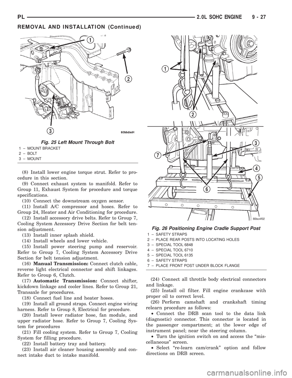
Fig. 25 Left Mount Through Bolt
1 ± MOUNT BRACKET
2 ± BOLT
3 ± MOUNT
Fig. 26 Positioning Engine Cradle Support Post
1 ± SAFETY STRAPS
2 ± PLACE REAR POSTS INTO LOCATING HOLES
3 ± SPECIAL TOOL 6848
4 ± SPECIAL TOOL 6710
5 ± SPECIAL TOOL 6135
6 ± SAFETY STRAPS
7 ± PLACE FRONT POST UNDER BLOCK FLANGE
PL2.0L SOHC ENGINE 9 - 27
REMOVAL AND INSTALLATION (Continued)
Page 914 of 1285
TRANSAXLE
TABLE OF CONTENTS
page page
NV T350 (A-578) MANUAL TRANSAXLE........ 131TH AUTOMATIC TRANSAXLE.............. 54
NV T350 (A-578) MANUAL TRANSAXLE
TABLE OF CONTENTS
page page
GENERAL INFORMATION
NV T350 (A578) MANUAL TRANSAXLE.........1
TRANSAXLE IDENTIFICATION................2
FLUID REQUIREMENTS....................2
SPECIAL ADDITIVES.......................2
SEALANTS..............................2
GEAR RATIOS............................2
GEARSHIFT PATTERN......................3
DIAGNOSIS AND TESTING
COMMON PROBLEM CAUSES...............3
HARD SHIFTING..........................3
NOISY OPERATION........................3
SLIPS OUT OF GEAR......................3
LOW LUBRICANT LEVEL....................4
FLUID LEAKS............................4
CLUTCH PROBLEMS.......................4
SERVICE PROCEDURES
FLUID DRAIN AND FILL.....................4
REMOVAL AND INSTALLATION
GEARSHIFT KNOB........................4
GEARSHIFT BOOT........................5
GEARSHIFT CABLE ASSEMBLY..............6
GEARSHIFT MECHANISM REPLACEMENT......9
VEHICLE SPEED SENSOR AND DRIVE
PINION...............................11
BACK-UP LAMP SWITCH...................12CROSSOVER LEVER......................12
SELECTOR LEVER.......................12
AXLE SHAFT SEALS......................13
SHIFT SHAFT SEALS......................13
TRANSAXLE............................14
DISASSEMBLY AND ASSEMBLY
TRANSAXLE............................18
INPUT SHAFT...........................31
OUTPUT SHAFT.........................36
DIFFERENTIAL..........................36
SYNCHRONIZER.........................41
SHIFT RAILS OVERHAUL..................42
TRANSAXLE CASE OVERHAUL..............42
CLEANING AND INSPECTION
TRANSAXLE............................48
SYNCHRONIZER.........................48
ADJUSTMENTS
GEARSHIFT CROSSOVER CABLE...........49
BEARING ADJUSTMENT PROCEDURE........50
DIFFERENTIAL BEARING PRELOAD
ADJUSTMENT..........................50
SPECIFICATIONS
NV T350 (A-578) SPECIFICATIONS...........51
SPECIAL TOOLS
NV T350 (A-578) MANUAL TRANSAXLE........52
GENERAL INFORMATION
NV T350 (A578) MANUAL TRANSAXLE
The NV T350 (A-578) transaxle is a fully synchro-
nized (except reverse), constant-mesh transaxle. The
transaxle case is constructed of die-cast aluminum,
and is a two-piece design (bell housing case half and
rear housing case half) with a steel end plate bearing
cover. All forward gears are in constant-mesh witheach other, which eliminates the need to move gears
together for engagement. This feature improves
response and eliminates gear ªclashº noises. The
reverse idler gear is supported and rotates on a spin-
dle idler shaft. Depending on application, a reverse
gear brake/blocking ring is available on some units
for shifting ease.
The NV T350 (A-578) transaxle also incorporates an
open differential, which converts power from the output
shaft pinion gear to the differential ring gear. The dif-
PLTRANSAXLE 21 - 1
Page 967 of 1285
31TH AUTOMATIC TRANSAXLE
TABLE OF CONTENTS
page page
GENERAL INFORMATION
IN VEHICLE SERVICE.....................55
FLUID REQUIREMENTS...................55
DESCRIPTION AND OPERATION
31TH GENERAL INFORMATION..............55
FLUID LEVEL AND CONDITION..............56
TORQUE CONVERTER CLUTCH.............56
HYDRAULIC CONTROL SYSTEM.............56
PRESSURE SUPPLY SYSTEM...............56
PRESSURE REGULATING VALVES...........56
FLOW CONTROL VALVES..................56
CLUTCHES, BAND SERVOS, AND
ACCUMULATOR........................57
BRAKE TRANSMISSION SHIFT INTERLOCK
SYSTEM..............................57
GEARSHIFT AND PARKING LOCK CONTROLS . . 57
COOLER BYPASS VALVE..................57
TORQUE CONVERTER CLUTCH SOLENOID
WIRING CONNECTOR...................58
GOVERNOR.............................58
DIAGNOSIS AND TESTING
TRANSAXLE PRELIMINARY DIAGNOSIS.......58
ROAD TEST.............................65
HYDRAULIC PRESSURE TESTS.............66
CLUTCH AND SERVO AIR PRESSURE TESTS . . 68
FLUID LEAKAGE-TRANSAXLE TORQUE
CONVERTER HOUSING AREA.............70
BRAKE TRANSMISSION SHIFT INTERLOCK....70
SERVICE PROCEDURES
TRANSAXLE FLUID AND FILTER SERVICE.....70
ALUMINUM THREAD REPAIR...............71
FLUSHING COOLERS AND TUBES...........72
OIL PUMP VOLUME CHECK................72
REMOVAL AND INSTALLATION
GEARSHIFT CABLE.......................73
GEARSHIFT MECHANISM..................76
THROTTLE VALVE (KICKDOWN) CABLE.......77
BRAKE TRANSMISSION SHIFT INTERLOCK
CABLE...............................79
INTERLOCK MECHANISM..................82
VEHICLE SPEED SENSOR PINION GEAR......83
PARK/NEUTRAL STARTING AND BACK-UP
LAMP SWITCH.........................84TRANSAXLE AND TORQUE CONVERTER......84
PUMP OIL SEAL.........................88
DISASSEMBLY AND ASSEMBLY
TRANSAXLE............................89
VALVE BODY............................91
OIL PUMP.............................104
FRONT CLUTCH........................105
REAR CLUTCH ASSEMBLY................108
FRONT PLANETARY AND ANNULUS
GEAR-RECONDITION...................110
LOW/REVERSE (REAR) SERVO-
RECONDITION........................112
ACCUMULATOR-RECONDITION............113
KICKDOWN SERVO (CONTROLLED LOAD)-
RECONDITION........................113
TRANSFER SHAFT REPAIR................114
PARKING PAWL.........................121
OUTPUT SHAFT REPAIR..................121
DIFFERENTIAL REPAIR...................129
CLEANING AND INSPECTION
VALVE BODY...........................135
ADJUSTMENTS
GEARSHIFT CABLE......................135
THROTTLE VALVE CABLE ADJUSTMENT
PROCEDURE.........................136
BRAKE TRANSMISSION SHIFT INTERLOCK
SYSTEM.............................137
BAND ADJUSTMENT.....................138
HYDRAULIC CONTROL PRESSURE
ADJUSTMENTS.......................138
BEARING ADJUSTMENT PROCEDURES......138
OUTPUT SHAFT BEARING................139
DIFFERENTIAL BEARING.................139
TRANSFER SHAFT BEARING..............140
SCHEMATICS AND DIAGRAMS
31TH TRANSAXLE HYDRAULIC SCHEMATIC . . 142
SPECIFICATIONS
31TH AUTOMATIC TRANSAXLE.............150
31TH TRANSAXLE TORQUE SPECIFICATIONS . 150
SPECIAL TOOLS
31TH AUTOMATIC TRANSAXLE.............151
21 - 54 TRANSAXLEPL
Page 970 of 1285
The kickdown valve makes possible a forced down-
shift from third to second, second to first, or third to
first (depending on vehicle speed). This can be done
by depressing the accelerator pedal past the detent
feel near wide open throttle.
The shuttle valve has two separate functions and
performs each independently of the other. The first is
providing fast release of the kickdown band, and
smooth front clutch engagement when a lift-foot
upshift from second to third is made. The second
function is to regulate the application of the kick-
down servo and band when making third±to±second
kickdown.
The bypass valve provides for smooth application
of the kickdown band on 1-2 upshifts.
The torque converter clutch solenoid allows for the
electronic control of the torque converter clutch. It
also disengages the torque converter at closed throt-
tle. This is done during engine warm-up and part-
throttle acceleration.
The switch valve directs oil to apply the torque
converter clutch in one position. The switch valve
releases the torque converter clutch in the other posi-
tion.
CLUTCHES, BAND SERVOS, AND
ACCUMULATOR
The front and rear clutch pistons, and both servo
pistons, are moved hydraulically to engage the
clutches and apply the bands. The pistons are
released by spring tension when hydraulic pressure
is released. On the 2-3 upshift, the kickdown servo
piston is released by spring tension and hydraulic
pressure.
The accumulator controls the hydraulic pressure
on the apply±side of the kickdown servo during the
1-2 upshift; thereby cushioning the kickdown band
application at any throttle position.
BRAKE TRANSMISSION SHIFT INTERLOCK
SYSTEM
The Brake Transmission Shifter/Ignition Interlock
(BTSI) is a cable and solenoid operated system. It
interconnects the automatic transmission floor
mounted shifter to the steering column ignition
switch. The system locks the shifter into the PARK
position. The interlock system is engaged whenever
the ignition switch is in the LOCK or ACCESSORY
position. An additional electrically activated feature
will prevent shifting out of the PARK position unless
the brake pedal is depressed at least one-half inch. A
magnetic holding device integral to the interlock
cable is energized when the ignition is in the RUN
position. When the key is in the RUN position and
the brake pedal is depressed, the shifter is unlocked
and will move into any position. The interlock systemalso prevents the ignition switch from being turned
to the LOCK or ACCESSORY position, unless the
shifter is in the gated PARK position.
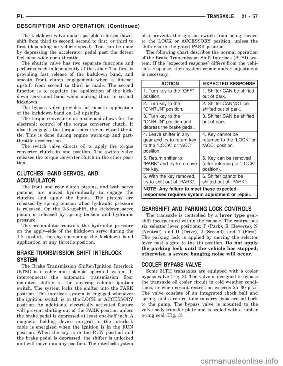
The following chart describes the normal operation
of the Brake Transmission Shift Interlock (BTSI) sys-
tem. If the ªexpected responseº differs from the vehi-
cle's response, then system repair and/or adjustment
is necessary.
GEARSHIFT AND PARKING LOCK CONTROLS
The transaxle is controlled by alever typegear-
shift incorporated within the console. The control has
six selector lever positions: P (Park), R (Reverse), N
(Neutral), and D (Drive), 2 (Second), and 1 (First).
The parking lock is applied by moving the selector
lever past a gate to the (P) position.Do not apply
the parking lock until the vehicle has stopped;
otherwise, a severe banging noise will occur.
COOLER BYPASS VALVE
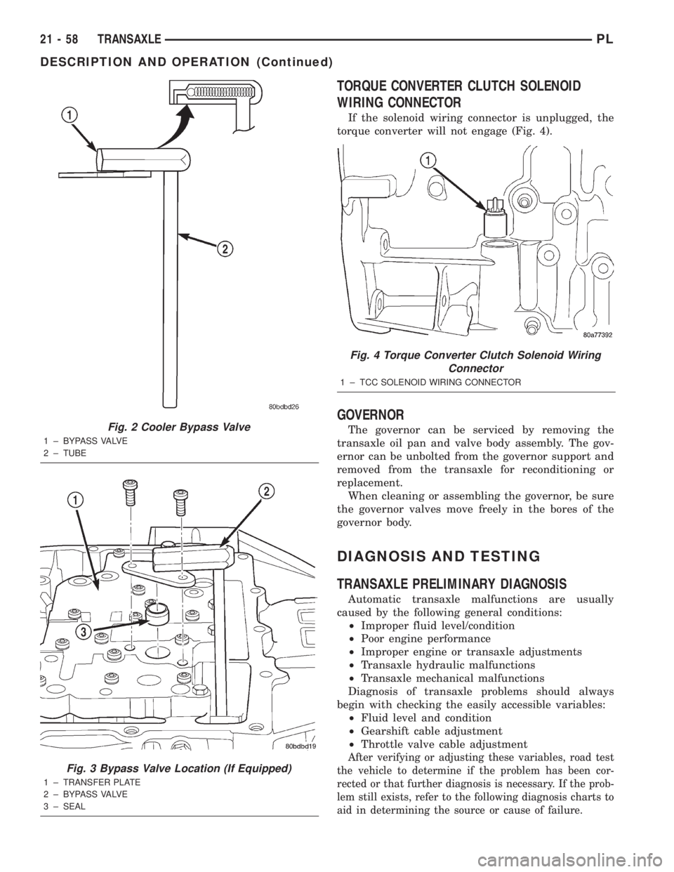
Some 31TH transaxles are equipped with a cooler
bypass valve (Fig. 2). The valve is designed to bypass
the transaxle oil cooler circuit in cold weather condi-
tions, or when circuit restriction exceeds 25±30 p.s.i.
The valve consists of an integrated check ball and
spring, and a return tube to carry bypassed oil back
to the pump. The bypass valve is mounted to the
valve body transfer plate and is sealed with a rubber
o-ring seal (Fig. 3).
ACTION EXPECTED RESPONSE
1. Turn key to the ªOFFº
position.1. Shifter CAN be shifted
out of park.
2. Turn key to the
9ON/RUNº position.2. Shifter CANNOT be
shifted out of park.
3. Turn key to the
ªON/RUNº position and
depress the brake pedal.3. Shifter CAN be shifted
out of park.
4. Leave shifter in any
gear and try to return key
to the ªLOCKº or9ACCº
position.4. Key cannot be
returned to the ªLOCKº or
ªACCº position.
5. Return shifter to
ªPARKº and try to remove
the key.5. Key can be removed
(after returning to ªLOCKº
position).
6. With the key removed,
try to shift out of ªPARKº.6. Shifter cannot be
shifted out of ªPARKº.
NOTE: Any failure to meet these expected
responses requires system adjustment or repair.
PLTRANSAXLE 21 - 57
DESCRIPTION AND OPERATION (Continued)
Page 971 of 1285
TORQUE CONVERTER CLUTCH SOLENOID
WIRING CONNECTOR
If the solenoid wiring connector is unplugged, the
torque converter will not engage (Fig. 4).
GOVERNOR
The governor can be serviced by removing the
transaxle oil pan and valve body assembly. The gov-
ernor can be unbolted from the governor support and
removed from the transaxle for reconditioning or
replacement.
When cleaning or assembling the governor, be sure
the governor valves move freely in the bores of the
governor body.
DIAGNOSIS AND TESTING
TRANSAXLE PRELIMINARY DIAGNOSIS
Automatic transaxle malfunctions are usually
caused by the following general conditions:
²Improper fluid level/condition
²Poor engine performance
²Improper engine or transaxle adjustments
²Transaxle hydraulic malfunctions
²Transaxle mechanical malfunctions
Diagnosis of transaxle problems should always
begin with checking the easily accessible variables:
²Fluid level and condition
²Gearshift cable adjustment
²Throttle valve cable adjustment
After verifying or adjusting these variables, road test
the vehicle to determine if the problem has been cor-
rected or that further diagnosis is necessary. If the prob-
lem still exists, refer to the following diagnosis charts to
aid in determining the source or cause of failure.
Fig. 2 Cooler Bypass Valve
1 ± BYPASS VALVE
2 ± TUBE
Fig. 3 Bypass Valve Location (If Equipped)
1 ± TRANSFER PLATE
2 ± BYPASS VALVE
3 ± SEAL
Fig. 4 Torque Converter Clutch Solenoid Wiring
Connector
1 ± TCC SOLENOID WIRING CONNECTOR
21 - 58 TRANSAXLEPL
DESCRIPTION AND OPERATION (Continued)