2000 DODGE NEON remote start
[x] Cancel search: remote startPage 215 of 1285
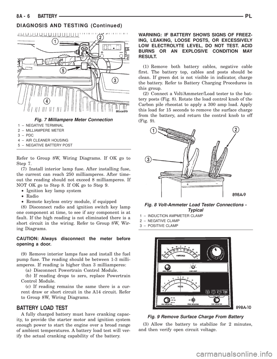
Refer to Group 8W, Wiring Diagrams. If OK go to
Step 7.
(7) Install interior lamp fuse. After installing fuse,
the current can reach 250 milliamperes. After time-
out the reading should not exceed 8 milliamperes. If
NOT OK go to Step 8. If OK go to Step 9.
²Ignition key lamp system
²Radio
²Remote keyless entry module, if equipped
(8) Disconnect radio and ignition switch key lamp
one component at time, to see if any component is at
fault. If the high reading is not eliminated there is a
short circuit in the wiring. Refer to Group 8W, Wir-
ing Diagrams.
CAUTION: Always disconnect the meter before
opening a door.
(9) Remove interior lamps fuse and install the fuel
pump fuse. The reading should be between 1-3 milli-
amperes. If reading is higher than 3 milliamperes:
(a) Disconnect Powertrain Control Module.
(b) If reading drops to zero, replace Powertrain
Control Module.
(c) If reading remains the same there is a cur-
rent draw or short circuit in the A14 circuit. Refer
to Group 8W, Wiring Diagrams.
BATTERY LOAD TEST
A fully charged battery must have cranking capac-
ity, to provide the starter motor and ignition system
enough power to start the engine over a broad range
of ambient temperatures. A battery load test will ver-
ify the actual cranking capability of the battery.WARNING: IF BATTERY SHOWS SIGNS OF FREEZ-
ING, LEAKING, LOOSE POSTS, OR EXCESSIVELY
LOW ELECTROLYTE LEVEL, DO NOT TEST. ACID
BURNS OR AN EXPLOSIVE CONDITION MAY
RESULT.
(1) Remove both battery cables, negative cable
first. The battery top, cables and posts should be
clean. If green dot is not visible in indicator, charge
the battery. Refer to Battery Charging Procedures in
this group.
(2) Connect a Volt/Ammeter/Load tester to the bat-
tery posts (Fig. 8). Rotate the load control knob of the
Carbon pile rheostat to apply a 300 amp load. Apply
this load for 15 seconds to remove the surface charge
from the battery, and return the control knob to off
(Fig. 9).
(3) Allow the battery to stabilize for 2 minutes,
and then verify open circuit voltage.
Fig. 7 Milliampere Meter Connection
1 ± NEGATIVE TERMINAL
2 ± MILLIAMPERE METER
3 ± PDC
4 ± AIR CLEANER HOUSING
5 ± NEGATIVE BATTERY POST
Fig. 8 Volt-Ammeter Load Tester Connections -
Typical
1 ± INDUCTION AMPMETER CLAMP
2 ± NEGATIVE CLAMP
3 ± POSITIVE CLAMP
Fig. 9 Remove Surface Charge From Battery
8A - 6 BATTERYPL
DIAGNOSIS AND TESTING (Continued)
Page 223 of 1285
DIAGNOSIS AND TESTING
CONTROL CIRCUIT
The starter control circuit has:
²Starter solenoid
²Starter relay
²Park/Neutral Starting and Back-Up Lamp
Switch with automatic transmissions
²Clutch Interlock/Upstop Switch with manual
transmissions
²Ignition switch
²Battery
²All related wiring and connections
²Double Start Override algorithm located in the
PCM
CAUTION: Before performing any starter tests, the
ignition and fuel systems must be disabled.
²To disable ignition and fuel systems, disconnect
the Automatic Shutdown Relay (ASD). The ASD relay
is located in the in the Power Distribution Center
(PDC). Refer to the PDC cover for the proper relay
location.
STARTER SOLENOID
WARNING: CHECK TO ENSURE THAT THE TRANS-
MISSION IS IN THE PARK POSITION WITH THE
PARKING BRAKE APPLIED
(1) Verify battery condition. Battery must be in
good condition with a full charge before performing
any starter tests. Refer to Battery Tests.
(2) Perform Starter Solenoid test BEFORE per-
forming the starter relay test.
(3) Raise the vehicle.
(4) Perform a visual inspection of the starter/
starter solenoid for corrosion, loose connections or
faulty wiring.
(5) Lower the vehicle.
(6) Locate and remove the starter relay from the
Power Distribution Center (PDC). Refer to the PDC
label for relay identification and location.
(7) Connect a starter switch or a jumper wire
between the remote battery positive post and termi-
nal 87 of the starter relay connector.
(a) If engine cranks, starter motor and starter
solenoid is good. Go to the Starter Relay Test.(b) If engine does not crank or solenoid chatters,
check wiring and connectors from starter relay to
starter solenoid for loose or corroded connections.
Check for corroded connections at starter termi-
nals.
(c) Repeat test. If engine still fails to crank prop-
erly, trouble is within starter or starter mounted
solenoid, and replace starter.
STARTER RELAY
WARNING: CHECK TO ENSURE THAT THE TRANS-
MISSION IS IN THE PARK POSITION WITH THE
PARKING BRAKE APPLIED.
RELAY TEST
The starter relay is located in the Power Distribu-
tion Center (PDC) in the engine compartment. Refer
to the PDC label for relay identification and location.
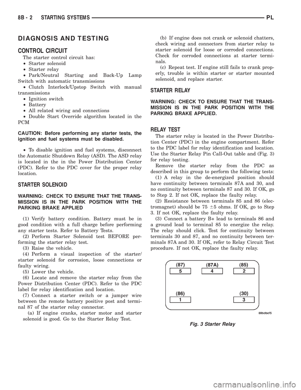
Use the Starter Relay Pin Call-Out table and (Fig. 3)
for relay testing.
Remove the starter relay from the PDC as
described in this group to perform the following tests:
(1) A relay in the de-energized position should
have continuity between terminals 87A and 30, and
no continuity between terminals 87 and 30. If OK, go
to Step 2. If not OK, replace the faulty relay.
(2) Resistance between terminals 85 and 86 (elec-
tromagnet) should be 7565 ohms. If OK, go to Step
3. If not OK, replace the faulty relay.
(3) Connect a battery B+ lead to terminals 86 and
a ground lead to terminal 85 to energize the relay.
The relay should click. Test for continuity between
terminals 30 and 87, and no continuity between ter-
minals 87A and 30. If OK, refer to Relay Circuit Test
procedure. If not OK, replace the faulty relay.
Fig. 3 Starter Relay
8B - 2 STARTING SYSTEMSPL
Page 366 of 1285
SERVICE PROCEDURES
DOUBLE ACTIVATION UNLOCK
The toggling of the double activation unlock fea-
ture (between enabled and disabled) can be per-
formed with the use of the DRB IIItscan tool, or by
the customer.
DRB lllTPROGRAMMING
When using the DRB IIItscan tool, select:
(1) ªTheft Alarmº
(2) ªVTSSº
(3) ªMiscellaneousº
and then the desired function.
CUSTOMER PROGRAMMING
(1) Open the driver door, sit in the driver seat, and
close the driver door.
(2) Turn the ignition switch to the RUN position
(without starting the vehicle) and then back to OFF.
Repeat this step three additional times (for a total of
four key ON/OFF cycles).
(3) Within ten seconds of switching the ignition
switch to the OFF position for the last time (at the
end of the fourth cycle in the above step), press the
driver interior door lock switch to UNLOCK.
(4) A single chime will be heard to verify that the
customer programmable toggle of the double activa-
tion unlock was successfully completed.
NOTE: When toggling the double activation unlock
feature (customer programmable), the toggle that
happens will be from the last state of the double
activation unlock. If the double activation unlock
feature was enabled, after the toggle process, it will
now be disabled and vice versa. There is no telltale
to inform you of which state the double activation
unlock feature is in.
ROLLING DOOR LOCKS
The toggling of the rolling door lock feature
(between enabled and disabled) can be performed
with the use of the DRB IIItscan tool or by the cus-
tomer.
DRB lllTPROGRAMMING
When using the DRB IIItscan tool, select:
(1) ªTheft Alarmº
(2) ªVTSSº(3) ªMiscellaneousº
and then the desired function.
CUSTOMER PROGRAMMING
(1) Open the driver door, sit in the driver seat, and
close the driver door.
(2) Turn the ignition switch to the RUN position
(without starting the vehicle) and then back to OFF.
Repeat this step three additional times (for a total of
four key ON/OFF cycles).
(3) Within ten seconds of switching the ignition
switch to the OFF position for the last time (at the
end of the fourth cycle in the above step), press the
driver interior door lock switch to LOCK.
(4) A single chime will be heard to verify that the
customer programmable toggle of the rolling door
locks was successfully completed.
NOTE: When toggling the rolling door locks (cus-
tomer programmable), the toggle that happens will
be from the last state of the rolling door locks. If
the rolling door locks were enabled, after the toggle
process, they will now be disabled and vice versa.
There is no telltale to inform you of which state the
rolling door locks are in.
REMOVAL AND INSTALLATION
DOOR LOCK MOTOR/LATCH
Refer to Group 23-Body, Front Door Latch Removal
and Installation.
DOOR LOCK SWITCH
REMOVAL
(1) Remove front door trim panel, refer to Group
23-Body, for Front Door Trim Panel Removal and
Installation.
(2) Disconnect wire connector.
(3) Remove two attaching screws.
(4) Remove the switch.
INSTALLATION
For installation, reverse the above procedures.
REMOTE KEYLESS ENTRY (RKE) MODULE
Refer to RKE Module Removal and Installation
under Remote Keyless Entry in this section.
PLPOWER LOCK SYSTEMS 8P - 3
Page 373 of 1285
VTSS disarming occurs upon normal vehicle entry
by unlocking either door via the key cylinders or
RKE transmitter, or by starting the vehicle with a
valid Sentry Key. This disarming will also halt the
alarm once it has been activated.
A tamper alert exists to notify the driver that the
system had been activated. This alert consists of 3
horn pulses when the vehicle is disarmed.
The VTSS will not arm by mechanically locking the
vehicle doors. This will manually override the sys-
tem.
In the dealer lot storage mode of operation, all of
the above descriptions of the VTSS are true with the
following exceptions:
²Remote Keyless Entry functions are disabled,
and cannot be used for arming/disarming the VTSS.
²The VTSS indicator is non-operational.
SENTRY KEY IMMOBILIZER SYSTEM (SKIS)
The Sentry Key Immobilizer System (SKIS) is
designed to provide passive protection against unau-
thorized vehicle use by preventing the engine from
operating while the system is armed. The primary
components of this system are the Sentry Key Immo-
bilizer Module (SKIM), the Sentry Key transponder,
the Vehicle Theft/Security System (VTSS) indicator
LED, and the Powertrain Control Module (PCM).
The SKIM is installed on the steering column near
the ignition lock cylinder. The transponder is located
under the molded rubber cap on the head of the igni-
tion key. The VTSS indicator LED is located in the
instrument cluster.
The SKIS includes three valid Sentry Key tran-
sponders from the factory, one being a valet key. This
is so the customer can self program new keys if one
is lost. If the customer wishes, additional non-coded
blank Sentry Keys are available. These blank keys
can be cut to match a valid ignition key, but the
engine will not start unless the key transponder is
also programmed to the vehicle. The SKIS will recog-
nize no more than eight valid Sentry Key transpon-
ders at any one time.
The SKIS performs a self-test each time the igni-
tion switch is turned to the ON position, and will
store Diagnostic Trouble Codes (DTC's) if a system
malfunction is detected. The SKIS can be diagnosed,
and any stored DTC can be retrieved using a DRB
llltscan tool as described in the proper Body Diag-
nostic Procedures Manual.
SENTRY KEY IMMOBILIZER MODULE (SKIM)
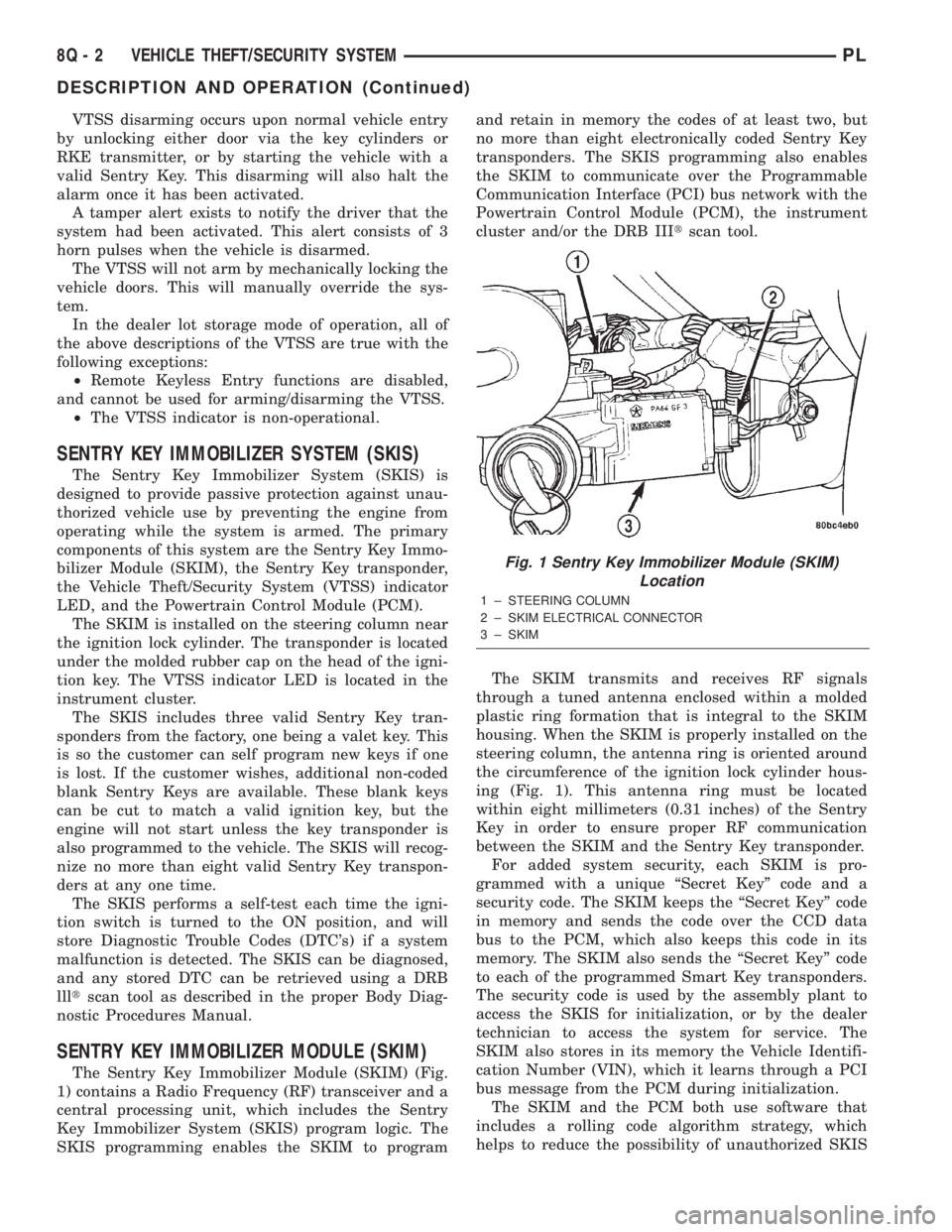
The Sentry Key Immobilizer Module (SKIM) (Fig.
1) contains a Radio Frequency (RF) transceiver and a
central processing unit, which includes the Sentry
Key Immobilizer System (SKIS) program logic. The
SKIS programming enables the SKIM to programand retain in memory the codes of at least two, but
no more than eight electronically coded Sentry Key
transponders. The SKIS programming also enables
the SKIM to communicate over the Programmable
Communication Interface (PCI) bus network with the
Powertrain Control Module (PCM), the instrument
cluster and/or the DRB IIItscan tool.
The SKIM transmits and receives RF signals
through a tuned antenna enclosed within a molded
plastic ring formation that is integral to the SKIM
housing. When the SKIM is properly installed on the
steering column, the antenna ring is oriented around
the circumference of the ignition lock cylinder hous-
ing (Fig. 1). This antenna ring must be located
within eight millimeters (0.31 inches) of the Sentry
Key in order to ensure proper RF communication
between the SKIM and the Sentry Key transponder.
For added system security, each SKIM is pro-
grammed with a unique ªSecret Keyº code and a
security code. The SKIM keeps the ªSecret Keyº code
in memory and sends the code over the CCD data
bus to the PCM, which also keeps this code in its
memory. The SKIM also sends the ªSecret Keyº code
to each of the programmed Smart Key transponders.
The security code is used by the assembly plant to
access the SKIS for initialization, or by the dealer
technician to access the system for service. The
SKIM also stores in its memory the Vehicle Identifi-
cation Number (VIN), which it learns through a PCI
bus message from the PCM during initialization.
The SKIM and the PCM both use software that
includes a rolling code algorithm strategy, which
helps to reduce the possibility of unauthorized SKIS
Fig. 1 Sentry Key Immobilizer Module (SKIM)
Location
1 ± STEERING COLUMN
2 ± SKIM ELECTRICAL CONNECTOR
3 ± SKIM
8Q - 2 VEHICLE THEFT/SECURITY SYSTEMPL
DESCRIPTION AND OPERATION (Continued)
Page 410 of 1285
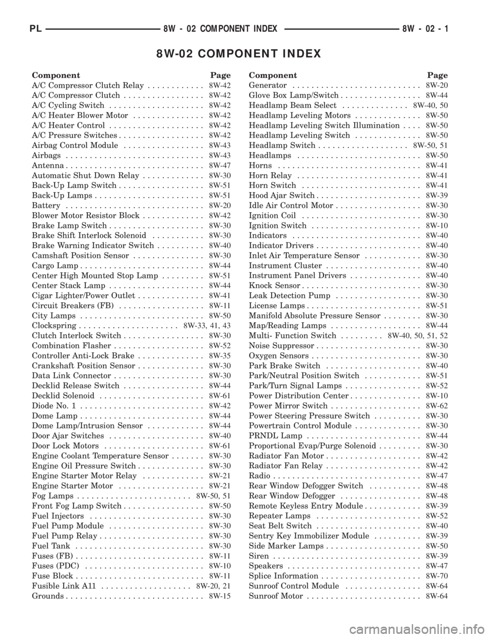
8W-02 COMPONENT INDEX
Component Page
A/C Compressor Clutch Relay............8W-42
A/C Compressor Clutch.................8W-42
A/C Cycling Switch....................8W-42
A/C Heater Blower Motor...............8W-42
A/C Heater Control....................8W-42
A/C Pressure Switches..................8W-42
Airbag Control Module.................8W-43
Airbags.............................8W-43
Antenna.............................8W-47
Automatic Shut Down Relay.............8W-30
Back-Up Lamp Switch..................8W-51
Back-Up Lamps.......................8W-51
Battery.............................8W-20
Blower Motor Resistor Block.............8W-42
Brake Lamp Switch....................8W-30
Brake Shift Interlock Solenoid...........8W-30
Brake Warning Indicator Switch..........8W-40
Camshaft Position Sensor...............8W-30
Cargo Lamp..........................8W-44
Center High Mounted Stop Lamp.........8W-51
Center Stack Lamp....................8W-44
Cigar Lighter/Power Outlet..............8W-41
Circuit Breakers (FB)..................8W-11
City Lamps..........................8W-50
Clockspring.....................8W-33, 41, 43
Clutch Interlock Switch.................8W-30
Combination Flasher...................8W-52
Controller Anti-Lock Brake..............8W-35
Crankshaft Position Sensor..............8W-30
Data Link Connector...................8W-30
Decklid Release Switch.................8W-44
Decklid Solenoid......................8W-61
Diode No. 1..........................8W-42
Dome Lamp..........................8W-44
Dome Lamp/Intrusion Sensor............8W-44
Door Ajar Switches....................8W-40
Door Lock Motors.....................8W-61
Engine Coolant Temperature Sensor.......8W-30
Engine Oil Pressure Switch..............8W-30
Engine Starter Motor Relay.............8W-21
Engine Starter Motor..................8W-21
Fog Lamps........................8W-50, 51
Front Fog Lamp Switch.................8W-50
Fuel Injectors........................8W-30
Fuel Pump Module....................8W-30
Fuel Pump Relay......................8W-30
Fuel Tank...........................8W-30
Fuses (FB)...........................8W-11
Fuses (PDC).........................8W-10
Fuse Block...........................8W-11
Fusible Link A11...................8W-20, 21
Grounds.............................8W-15Component Page
Generator...........................8W-20
Glove Box Lamp/Switch.................8W-44
Headlamp Beam Select..............8W-40, 50
Headlamp Leveling Motors..............8W-50
Headlamp Leveling Switch Illumination....8W-50
Headlamp Leveling Switch..............8W-50
Headlamp Switch...................8W-50, 51
Headlamps..........................8W-50
Horns..............................8W-41
Horn Relay..........................8W-41
Horn Switch.........................8W-41
Hood Ajar Switch......................8W-39
Idle Air Control Motor..................8W-30
Ignition Coil.........................8W-30
Ignition Switch.......................8W-10
Indicators...........................8W-40
Indicator Drivers......................8W-40
Inlet Air Temperature Sensor............8W-30
Instrument Cluster....................8W-40
Instrument Panel Drivers...............8W-40
Knock Sensor.........................8W-30
Leak Detection Pump..................8W-30
License Lamps........................8W-51
Manifold Absolute Pressure Sensor........8W-30
Map/Reading Lamps...................8W-44
Multi- Function Switch.........8W-40, 50, 51, 52
Noise Suppressor......................8W-30
Oxygen Sensors.......................8W-30
Park Brake Switch....................8W-40
Park/Neutral Position Switch............8W-51
Park/Turn Signal Lamps................8W-52
Power Distribution Center...............8W-10
Power Mirror Switch...................8W-62
Power Steering Pressure Switch..........8W-30
Powertrain Control Module..............8W-30
PRNDL Lamp........................8W-44
Proportional Evap/Purge Solenoid.........8W-30
Radiator Fan Motor....................8W-42
Radiator Fan Relay....................8W-42
Radio...............................8W-47
Rear Window Defogger Switch...........8W-48
Rear Window Defogger.................8W-48
Remote Keyless Entry Module............8W-39
Repeater Lamps......................8W-52
Seat Belt Switch......................8W-40
Sentry Key Immobilizer Module..........8W-39
Side Marker Lamps....................8W-50
Siren...............................8W-39
Speakers............................8W-47
Splice Information.....................8W-70
Sunroof Control Module................8W-64
Sunroof Motor........................8W-64
PL8W - 02 COMPONENT INDEX 8W - 02 - 1
Page 412 of 1285
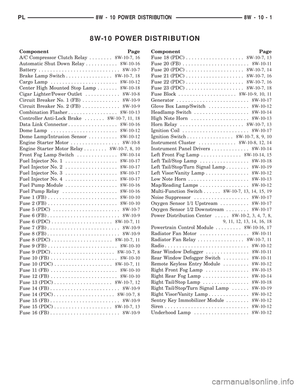
8W-10 POWER DISTRIBUTION
Component Page
A/C Compressor Clutch Relay........8W-10-7, 16
Automatic Shut Down Relay...........8W-10-16
Battery............................8W-10-7
Brake Lamp Switch................8W-10-7, 18
Cargo Lamp.......................8W-10-12
Center High Mounted Stop Lamp.......8W-10-18
Cigar Lighter/Power Outlet............8W-10-8
Circuit Breaker No. 1 (FB).............8W-10-9
Circuit Breaker No. 2 (FB).............8W-10-9
Combination Flasher.................8W-10-13
Controller Anti-Lock Brake.......8W-10-7, 11, 18
Data Link Connector.................8W-10-16
Dome Lamp.......................8W-10-12
Dome Lamp/Intrusion Sensor..........8W-10-12
Engine Starter Motor.................8W-10-8
Engine Starter Motor Relay........8W-10-7, 8, 10
Front Fog Lamp Switch..............8W-10-14
Fuel Injector No. 1..................8W-10-17
Fuel Injector No. 2..................8W-10-17
Fuel Injector No. 3..................8W-10-17
Fuel Injector No. 4..................8W-10-17
Fuel Pump Module..................8W-10-16
Fuel Pump Relay...................8W-10-16
Fuse 1 (FB)........................8W-10-10
Fuse 2 (FB)........................8W-10-10
Fuse 5 (PDC).......................8W-10-7
Fuse 6 (FB).........................8W-10-9
Fuse 6 (PDC).....................8W-10-7, 11
Fuse 7 (FB).........................8W-10-9
Fuse 8 (FB).........................8W-10-9
Fuse 8 (PDC).....................8W-10-7, 11
Fuse 9 (FB)........................8W-10-10
Fuse 9 (PDC)......................8W-10-7, 8
Fuse 10 (FB).......................8W-10-10
Fuse 10 (PDC)....................8W-10-7, 11
Fuse 11 (FB).......................8W-10-10
Fuse 12 (FB).......................8W-10-10
Fuse 13 (PDC)....................8W-10-7, 12
Fuse 14 (FB)........................8W-10-9
Fuse 14 (PDC).....................8W-10-7, 8
Fuse 15 (FB)........................8W-10-9
Fuse 15 (PDC)....................8W-10-7, 13
Fuse 16 (FB)........................8W-10-9Component Page
Fuse 18 (PDC)....................8W-10-7, 13
Fuse 20 (FB).......................8W-10-11
Fuse 20 (PDC)....................8W-10-7, 14
Fuse 21 (PDC)....................8W-10-7, 16
Fuse 22 (PDC)....................8W-10-7, 16
Fuse 23 (PDC)....................8W-10-7, 18
Fuse Block....................8W-10-9, 10, 11
Generator.........................8W-10-17
Glove Box Lamp/Switch..............8W-10-12
Headlamp Switch...................8W-10-14
High Note Horn....................8W-10-13
Horn Relay......................8W-10-7, 13
Ignition Coil.......................8W-10-17
Ignition Switch................8W-10-7, 8, 9, 10
Instrument Cluster.............8W-10-8, 12, 14
Instrument Panel Drivers.............8W-10-14
Left Front Fog Lamp..............8W-10-14, 15
Left Tail/Stop Lamp.................8W-10-18
Left Tail/Stop/Turn Signal Lamp........8W-10-19
Left Visor/Vanity Lamp...............8W-10-12
Low Note Horn.....................8W-10-13
Map/Reading Lamps.................8W-10-12
Multi-Function Switch......8W-10-7, 13, 14, 15, 19
Noise Suppressor...................8W-10-17
Oxygen Sensor 1/1 Upstream..........8W-10-17
Oxygen Sensor 1/2 Downstream........8W-10-17
Power Distribution Center.....8W-10-2, 3, 4, 7, 8,
9, 11, 12, 13, 14, 16, 18
Powertrain Control Module.........8W-10-16, 17
Radiator Fan Motor.................8W-10-11
Radiator Fan Relay................8W-10-7, 11
Radio.............................8W-10-12
Rear Window Defogger...............8W-10-11
Rear Window Defogger Switch.........8W-10-11
Remote Keyless Entry Module.........8W-10-12
Right Front Fog Lamp...............8W-10-15
Right Rear Fog Lamp................8W-10-14
Right Tail/Stop Lamp................8W-10-18
Right Tail/Stop/Turn Signal Lamp......8W-10-19
Right Visor/Vanity Lamp..............8W-10-12
Sentry Key Immobilizer Module........8W-10-12
Siren.............................8W-10-12
Underhood Lamp...................8W-10-12
PL8W - 10 POWER DISTRIBUTION 8W - 10 - 1
Page 474 of 1285
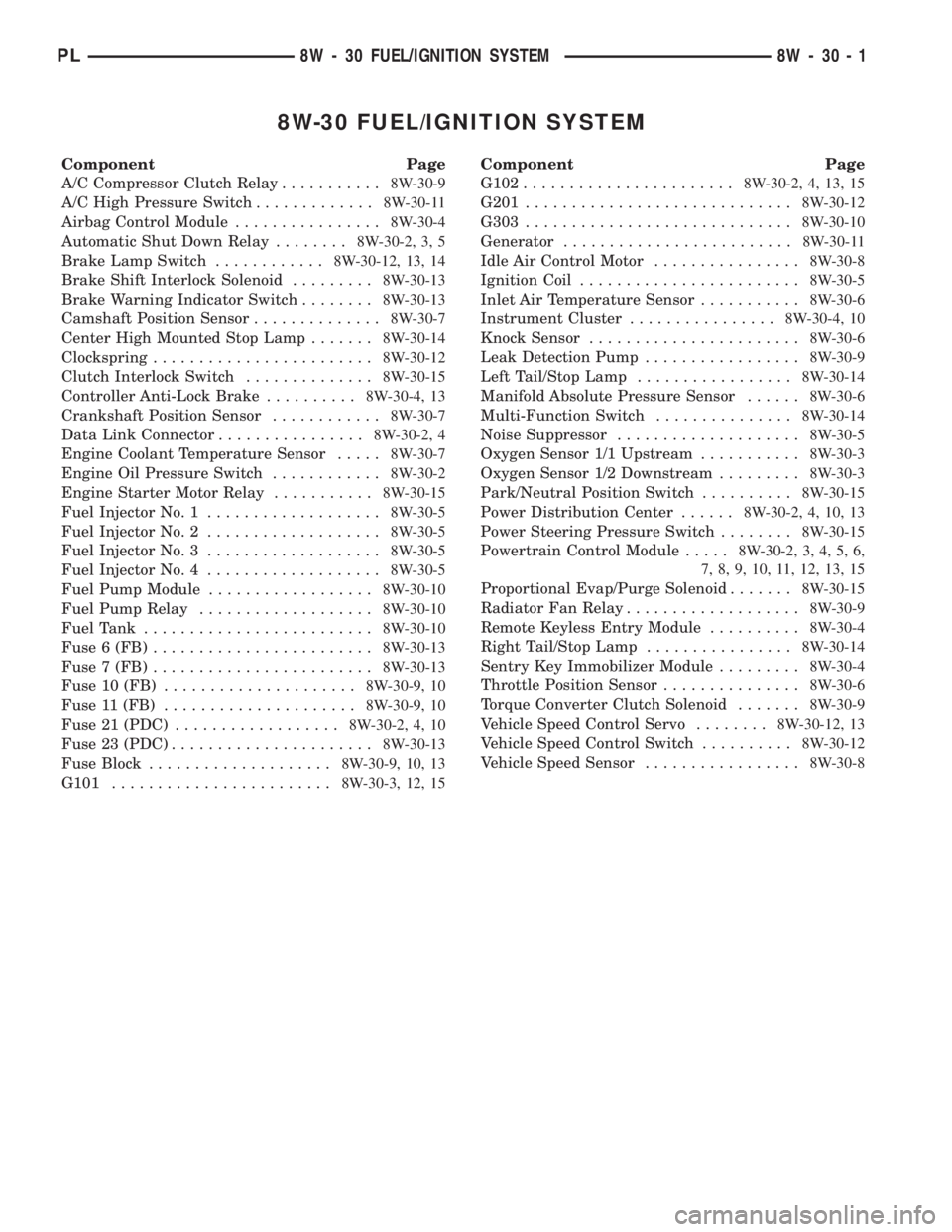
8W-30 FUEL/IGNITION SYSTEM
Component Page
A/C Compressor Clutch Relay...........8W-30-9
A/C High Pressure Switch.............8W-30-11
Airbag Control Module................8W-30-4
Automatic Shut Down Relay........8W-30-2, 3, 5
Brake Lamp Switch............8W-30-12, 13, 14
Brake Shift Interlock Solenoid.........8W-30-13
Brake Warning Indicator Switch........8W-30-13
Camshaft Position Sensor..............8W-30-7
Center High Mounted Stop Lamp.......8W-30-14
Clockspring........................8W-30-12
Clutch Interlock Switch..............8W-30-15
Controller Anti-Lock Brake..........8W-30-4, 13
Crankshaft Position Sensor............8W-30-7
Data Link Connector................8W-30-2, 4
Engine Coolant Temperature Sensor.....8W-30-7
Engine Oil Pressure Switch............8W-30-2
Engine Starter Motor Relay...........8W-30-15
Fuel Injector No. 1...................8W-30-5
Fuel Injector No. 2...................8W-30-5
Fuel Injector No. 3...................8W-30-5
Fuel Injector No. 4...................8W-30-5
Fuel Pump Module..................8W-30-10
Fuel Pump Relay...................8W-30-10
Fuel Tank.........................8W-30-10
Fuse 6 (FB)........................8W-30-13
Fuse 7 (FB)........................8W-30-13
Fuse 10 (FB).....................8W-30-9, 10
Fuse 11 (FB).....................8W-30-9, 10
Fuse 21 (PDC)..................8W-30-2, 4, 10
Fuse 23 (PDC)......................8W-30-13
Fuse Block....................8W-30-9, 10, 13
G101........................8W-30-3, 12, 15Component Page
G102.......................8W-30-2, 4, 13, 15
G201.............................8W-30-12
G303.............................8W-30-10
Generator.........................8W-30-11
Idle Air Control Motor................8W-30-8
Ignition Coil........................8W-30-5
Inlet Air Temperature Sensor...........8W-30-6
Instrument Cluster................8W-30-4, 10
Knock Sensor.......................8W-30-6
Leak Detection Pump.................8W-30-9
Left Tail/Stop Lamp.................8W-30-14
Manifold Absolute Pressure Sensor......8W-30-6
Multi-Function Switch...............8W-30-14
Noise Suppressor....................8W-30-5
Oxygen Sensor 1/1 Upstream...........8W-30-3
Oxygen Sensor 1/2 Downstream.........8W-30-3
Park/Neutral Position Switch..........8W-30-15
Power Distribution Center......8W-30-2, 4, 10, 13
Power Steering Pressure Switch........8W-30-15
Powertrain Control Module.....8W-30-2, 3, 4, 5, 6,
7, 8, 9, 10, 11, 12, 13, 15
Proportional Evap/Purge Solenoid.......8W-30-15
Radiator Fan Relay...................8W-30-9
Remote Keyless Entry Module..........8W-30-4
Right Tail/Stop Lamp................8W-30-14
Sentry Key Immobilizer Module.........8W-30-4
Throttle Position Sensor...............8W-30-6
Torque Converter Clutch Solenoid.......8W-30-9
Vehicle Speed Control Servo........8W-30-12, 13
Vehicle Speed Control Switch..........8W-30-12
Vehicle Speed Sensor.................8W-30-8
PL8W - 30 FUEL/IGNITION SYSTEM 8W - 30 - 1
Page 1148 of 1285
(2) Pull upward at rear end of outer belt weather-
strip.
(3) Remove outer belt weatherstrip from vehicle
(Fig. 29).INSTALLATION
(1) Starting at leading edge of door, press weather-
strip onto door.
(2) Operate window and check for interference
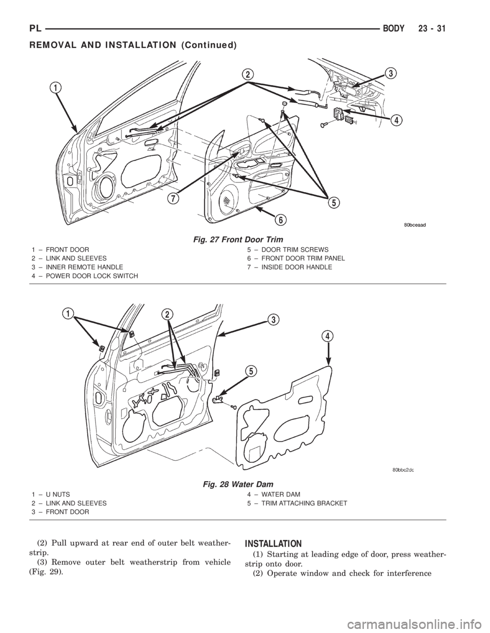
Fig. 27 Front Door Trim
1 ± FRONT DOOR
2 ± LINK AND SLEEVES
3 ± INNER REMOTE HANDLE
4 ± POWER DOOR LOCK SWITCH5 ± DOOR TRIM SCREWS
6 ± FRONT DOOR TRIM PANEL
7 ± INSIDE DOOR HANDLE
Fig. 28 Water Dam
1 ± U NUTS
2 ± LINK AND SLEEVES
3 ± FRONT DOOR4 ± WATER DAM
5 ± TRIM ATTACHING BRACKET
PLBODY 23 - 31
REMOVAL AND INSTALLATION (Continued)