2000 DODGE NEON pressure
[x] Cancel search: pressurePage 4 of 1285
MAINTENANCE SCHEDULES
TABLE OF CONTENTS
page page
DESCRIPTION AND OPERATION
MAINTENANCE SCHEDULES................3
SPECIFICATIONS
UNSCHEDULED INSPECTION................3SCHEDULE ± A...........................3
SCHEDULE ± B...........................4
DESCRIPTION AND OPERATION
MAINTENANCE SCHEDULES
There are two maintenance schedules that show
proper service for your vehicle.
First is Schedule ±A. It lists all the scheduled
maintenance to be performed under ªnormalº operat-
ing conditions.
Second is Schedule ±B. It is a schedule for vehi-
cles that are operated under the following conditions:
²Frequent short trip driving less than 5 miles (8
km)
²Frequent driving in dusty conditions
²Extensive idling
²More than 50% of the driving is at sustained
high speeds during hot weather, above 90É F (32É C)
SPECIFICATIONS
UNSCHEDULED INSPECTION
At Each Stop For Fuel
²Check engine oil level and add as required.
²Check windshield washer solvent and add as
required.
Once A Month
²Check tire pressure and look for unusual wear
or damage.
²Inspect the battery and clean and tighten termi-
nals as required.
²Check fluid levels of coolant reservoir, brake
master cylinder, power steering and transmission.
Add fluid as required.
²Check all lights and all other electrical items for
correct operation.
At Each Oil Change
²Inspect the exhaust system.
²Inspect brake hoses.
²Inspect the CV joints and front suspension com-
ponent boots and seals.²Rotate the tires at each oil change interval
shown on Schedule ± A (7,500 miles - 12 000 km) or
every other interval on Schedule ± B (6,000 miles -
10 000 km).
²Check the engine coolant level, hoses, and
clamps.
If mileage is less than 7,500 miles (12 000 km)
yearly, replace the engine oil filter at each oil change.
EMISSION CONTROL SYSTEM MAINTENANCE
The scheduled emission maintenance listed inbold
typeon the Maintenance Schedules, must be done at
the mileage specified to assure the continued proper
functioning of the emission control system. These,
and all other maintenance services included in this
manual, should be done to provide the best vehicle
performance and reliability. More frequent mainte-
nance may be needed for vehicles in severe operating
conditions such as dusty areas and very short trip
driving.
FLUID FILL POINTS AND LUBRICATION
LOCATIONS
The fluid fill/check locations and lubrication loca-
tions are located in each applicable group.
SCHEDULE ± A
7,500 Miles (12 000 km) or at 6 months
²Change the engine oil.
²Replace the engine oil filter.
15,000 Miles (24 000 km) or at 12 months
²Change the engine oil.
²Replace the engine oil filter.
²Adjust the drive belt tension.
22,500 Miles (36 000 km) or at 18 months
²Change the engine oil.
²Replace the engine oil filter.
²Inspect the front brake pads and rear brake lin-
ings.
PLLUBRICATION AND MAINTENANCE 0 - 3
Page 15 of 1285
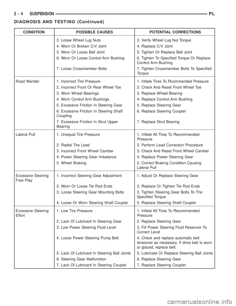
CONDITION POSSIBLE CAUSES POTENTIAL CORRECTIONS
3. Loose Wheel Lug Nuts 3. Verify Wheel Lug Nut Torque
4. Worn Or Broken C/V Joint 4. Replace C/V Joint
5. Worn Or Loose Ball Joint 5. Tighten Or Replace Ball Joint
6. Worn Or Loose Control Arm Bushing 6. Tighten To Specified Torque Or Replace
Control Arm Bushing
7. Loose Crossmember Bolts 7. Tighten Crossmember Bolts To Specified
Torque
Road Wander 1. Incorrect Tire Pressure 1. Inflate Tires To Rcommended Pressure
2. Incorrect Front Or Rear Wheel Toe 2. Check And Reset Front Wheel Toe
3. Worn Wheel Bearings 3. Replace Wheel Bearing
4. Worn Control Arm Bushings 4. Replace Control Arm Bushing
5. Excessive Friction In Steering Gear 5. Replace Steering Gear
6. Excessive Friction In Steering Shaft
Coupling6. Replace Steering Coupler
7. Excessive Friction In Strut Upper
Bearing7. Replace Strut Bearing
Lateral Pull 1. Unequal Tire Pressure 1. Inflate All Tires To Recommended
Pressure
2. Radial Tire Lead 2. Perform Lead Correction Procedure
3. Incorrect Front Wheel Camber 3. Check And Reset Front Wheel Camber
4. Power Steering Gear Imbalance 4. Replace Power Steering Gear
5. Wheel Braking 5. Correct Braking Condition Causing
Lateral Pull
Excessive Steering
Free Play1. Incorrect Steering Gear Adjustment 1. Adjust Or Replace Steering Gear
2. Worn Or Loose Tie Rod Ends 2. Replace Or Tighten Tie Rod Ends
3. Loose Steering Gear Mounting Bolts 3. Tighten Steering Gear Bolts To The
Specified Torque
4. Loose Or Worn Steering Shaft Coupler 5. Replace Steering Shaft Coupler
Excessive Steering
Effort1. Low Tire Pressure 1. Inflate All Tires To Recommended
Pressure
2. Lack Of Lubricant In Steering Gear 2. Replace Steering Gear
3. Low Power Steering Fluid Level 3. Fill Power Steering Fluid Reservoir To
Correct Level
4. Loose Power Steering Pump Belt 4. Check and replace automatic belt
tensioner as necessary. If drive belt is worn
or glazed, replace belt.
5. Lack Of Lubricant In Steering Ball Joints 5. Lubricate Or Replace Steering Ball Joints
6. Steering Gear Malfunction 6. Replace Steering Gear
7. Lack Of Lubricant In Steering Coupler 7. Replace Steering Coupler
2 - 4 SUSPENSIONPL
DIAGNOSIS AND TESTING (Continued)
Page 16 of 1285
SERVICE PROCEDURES
CURB HEIGHT MEASUREMENT
The wheel alignment is to be checked and all align-
ment adjustments made with the vehicle at its
required curb height specification.
Vehicle height is to be checked with the vehicle on
a flat, level surface, preferably a vehicle alignment
rack. The tires are to be inflated to the recommended
pressure. All tires are to be the same size as stan-
dard equipment. Vehicle height is checked with the
fuel tank full of fuel, and no passenger or luggage
compartment load.
Vehicle height is not adjustable. If the measure-
ment is not within specifications, inspect the vehicle
for bent or weak suspension components. Compare
the parts tag on the suspect coil spring(s) to the
parts book and the vehicle sales code, checking for a
match. Once removed from the vehicle, compare thecoil spring height to a correct new or known good coil
spring. The heights should vary if the suspect spring
is weak.
NOTE: Prior to reading the curb height measure-
ment, the front an rear of the vehicle should be
jounced. Induce jounce by grasping the center of
the rear, then front bumper (or fascia) and jouncing
the vehicle an equal number of times. Release the
bumper at the bottom of the jounce cycle.
(1) Measure from the inboard edge of the wheel
opening fender lip directly above the wheel center
(spindle), to the floor or alignment rack surface.
(2) When measuring, maximum left-to-right differ-
ential is not to exceed 10 mm (0.39 in.).
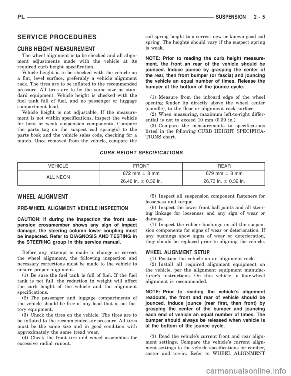
(3) Compare the measurements to specifications
listed in the following CURB HEIGHT SPECIFICA-
TIONS chart.
CURB HEIGHT SPECIFICATIONS
VEHICLE FRONT REAR
ALL NEON672 mm68 mm 679 mm68mm
26.46 in.60.32 in. 26.73 in.60.32 in.
WHEEL ALIGNMENT
PRE-WHEEL ALIGNMENT VEHICLE INSPECTION
CAUTION: If during the inspection the front sus-
pension crossmember shows any sign of impact
damage, the steering column lower coupling must
be inspected. Refer to DIAGNOSIS AND TESTING in
the STEERING group in this service manual.
Before any attempt is made to change or correct
the wheel alignment, the following inspection and
necessary corrections must be made to the vehicle to
ensure proper alignment.
(1) Be sure the fuel tank is full of fuel. If the fuel
tank is not full, the reduction in weight will affect
the curb height of the vehicle and the alignment
specifications.
(2) The passenger and luggage compartments of
the vehicle should be free of any load that is not fac-
tory equipment.
(3) Check the tires on the vehicle. The tires are to
be inflated to the recommended air pressure. All tires
must be the same size and in good condition with
approximately the same tread wear.
(4) Check the front tire and wheel assemblies for
excessive radial runout.(5) Inspect all suspension component fasteners for
looseness and torque.
(6) Inspect the lower front ball joints and all steer-
ing linkage for looseness and any sign of wear or
damage.
(7) Inspect the rubber bushings on all the suspen-
sion components for signs of wear or deterioration. If
any bushings show signs of wear or deterioration,
they should be replaced prior to aligning the vehicle.
WHEEL ALIGNMENT SETUP
(1) Position the vehicle on an alignment rack.
(2) Install all required alignment equipment on
the vehicle, per the alignment equipment manufac-
turer's instructions. On this vehicle, a four-wheel
alignment is recommended.
NOTE: Prior to reading the vehicle's alignment
readouts, the front and rear of vehicle should be
jounced. Induce jounce (rear first, then front) by
grasping the center of the bumper and jouncing
each end of vehicle an equal number of times. The
bumper should always be released when vehicle is
at the bottom of the jounce cycle.
(3) Read the vehicle's current front and rear align-
ment settings. Compare the vehicle's current align-
ment settings to the vehicle specifications for camber,
caster and toe-in. Refer to WHEEL ALIGNMENT
PLSUSPENSION 2 - 5
Page 25 of 1285
CAUTION: No attempt should be made to service
the headless grease fitting on the ball joint. It has
been purposely snapped off by the manufacturer to
avoid over-greasing.
STABILIZER BAR (FRONT)
Inspect for broken, cracked or distorted stabilizer
bar cushions and retainers. Inspect for worn or dam-
aged stabilizer bar links (Fig. 1).
SERVICE PROCEDURES
LUBRICATION
There are no serviceable lubrication points on the
front suspension. The front lower ball joints have
grease fittings which have had the head snapped off
by the manufacturer after they have been filled. This
has been done to eliminate the possibility of damag-
ing the non-vented seals. Grease will not leak from
the broken grease fittings. The ball joints are sealed
for life and require no maintenance.
CAUTION: No attempt should be made to replace
the ball joint grease fitting with a new fitting, then
filling the ball joint with grease. Damage to the
grease seal can result.
REMOVAL AND INSTALLATION
SERVICE WARNINGS AND CAUTIONS
WARNING: DO NOT REMOVE THE STRUT SHAFT
NUT WHILE STRUT ASSEMBLY IS INSTALLED IN
VEHICLE, OR BEFORE THE COIL SPRING IS COM-
PRESSED WITH A COMPRESSION TOOL. THE
SPRING IS HELD UNDER HIGH PRESSURE.
CAUTION: Only frame contact hoisting equipment
can be used on this vehicle. All vehicles have a
fully independent rear suspension. The vehicles
cannot be hoisted using equipment designed to lift
a vehicle by the rear axle. If this type of hoisting
equipment is used, damage to rear suspension
components will occur.
CAUTION: At no time when servicing a vehicle can
a sheet metal screw, bolt, or other metal fastener be
installed in the shock tower to take the place of an
original plastic clip. It may come into contact with
the strut or coil spring.CAUTION: Wheel bearing damage will result if after
loosening the hub nut, the vehicle is rolled on the
ground or the weight of the vehicle is allowed to be
supported by the tires for a length of time.
STRUT ASSEMBLY (FRONT)
NOTE: Before proceeding with this procedure,
review SERVICE WARNINGS AND CAUTIONS at the
beginning of REMOVAL AND INSTALLATION in this
section.
REMOVAL
(1) Raise the vehicle. Refer to HOISTING in the
LUBRICATION AND MAINTENANCE group for the
proper lifting procedure.
(2) Remove tire and wheel assembly from location
on front of vehicle requiring strut removal.
(3) If both strut assemblies are to be removed,
mark the strut assemblies right or left according to
which side of the vehicle they were removed from.
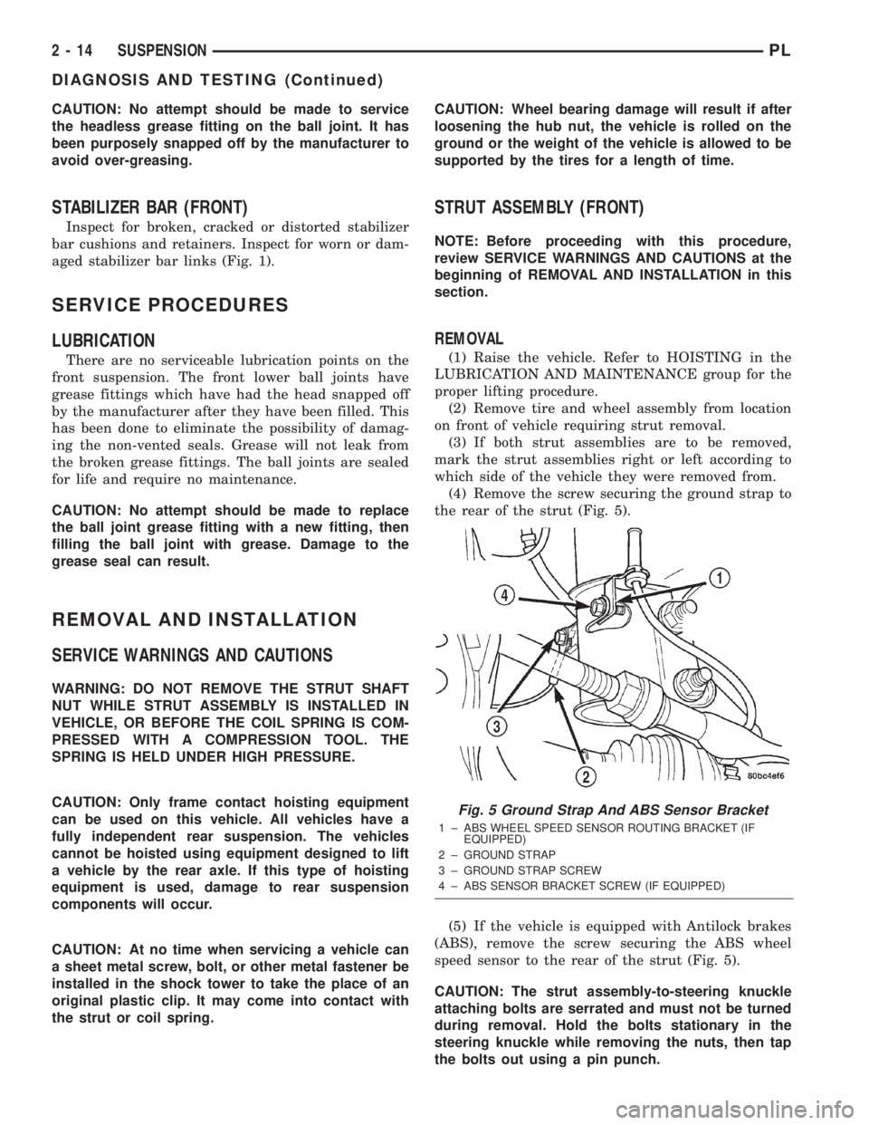
(4) Remove the screw securing the ground strap to
the rear of the strut (Fig. 5).
(5) If the vehicle is equipped with Antilock brakes
(ABS), remove the screw securing the ABS wheel
speed sensor to the rear of the strut (Fig. 5).
CAUTION: The strut assembly-to-steering knuckle
attaching bolts are serrated and must not be turned
during removal. Hold the bolts stationary in the
steering knuckle while removing the nuts, then tap
the bolts out using a pin punch.
Fig. 5 Ground Strap And ABS Sensor Bracket
1 ± ABS WHEEL SPEED SENSOR ROUTING BRACKET (IF
EQUIPPED)
2 ± GROUND STRAP
3 ± GROUND STRAP SCREW
4 ± ABS SENSOR BRACKET SCREW (IF EQUIPPED)
2 - 14 SUSPENSIONPL
DIAGNOSIS AND TESTING (Continued)
Page 34 of 1285
removed from, and which strut the coil spring was
removed from.
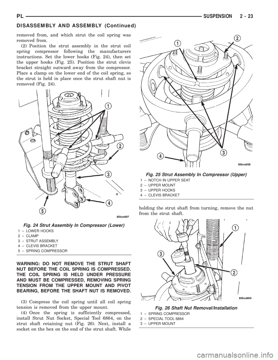
(2) Position the strut assembly in the strut coil
spring compressor following the manufacturers
instructions. Set the lower hooks (Fig. 24), then set
the upper hooks (Fig. 25). Position the strut clevis
bracket straight outward away from the compressor.
Place a clamp on the lower end of the coil spring, so
the strut is held in place once the strut shaft nut is
removed (Fig. 24).
WARNING: DO NOT REMOVE THE STRUT SHAFT
NUT BEFORE THE COIL SPRING IS COMPRESSED.
THE COIL SPRING IS HELD UNDER PRESSURE
AND MUST BE COMPRESSED, REMOVING SPRING
TENSION FROM THE UPPER MOUNT AND PIVOT
BEARING, BEFORE THE SHAFT NUT IS REMOVED.
(3) Compress the coil spring until all coil spring
tension is removed from the upper mount.
(4) Once the spring is sufficiently compressed,
install Strut Nut Socket, Special Tool 6864, on the
strut shaft retaining nut (Fig. 26). Next, install a
socket on the hex on the end of the strut shaft. Whileholding the strut shaft from turning, remove the nut
from the strut shaft.
Fig. 24 Strut Assembly In Compressor (Lower)
1 ± LOWER HOOKS
2 ± CLAMP
3 ± STRUT ASSEMBLY
4 ± CLEVIS BRACKET
5 ± SPRING COMPRESSOR
Fig. 25 Strut Assembly In Compressor (Upper)
1 ± NOTCH IN UPPER SEAT
2 ± UPPER MOUNT
3 ± UPPER HOOKS
4 ± CLEVIS BRACKET
Fig. 26 Shaft Nut Removal/Installation
1 ± SPRING COMPRESSOR
2 ± SPECIAL TOOL 6864
3 ± UPPER MOUNT
PLSUSPENSION 2 - 23
DISASSEMBLY AND ASSEMBLY (Continued)
Page 42 of 1285
ball joint bottoms against the lower control arm ball
joint bore. Do not apply excessive pressure against
ball joint and lower control arm once the ball joint
bottoms.
(5) Remove the tools and arm from the hydraulic
press.
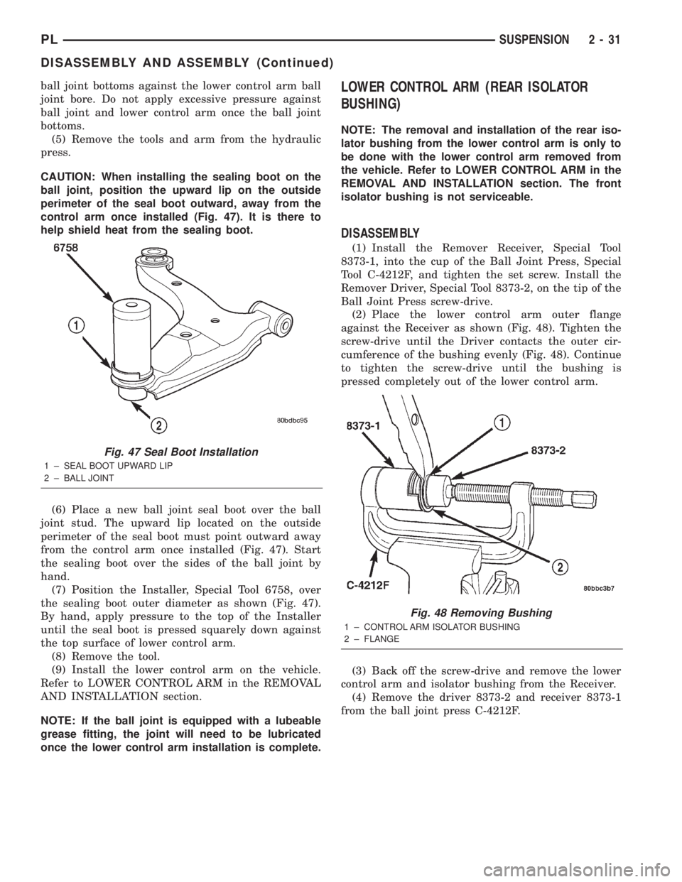
CAUTION: When installing the sealing boot on the
ball joint, position the upward lip on the outside
perimeter of the seal boot outward, away from the
control arm once installed (Fig. 47). It is there to
help shield heat from the sealing boot.
(6) Place a new ball joint seal boot over the ball
joint stud. The upward lip located on the outside
perimeter of the seal boot must point outward away
from the control arm once installed (Fig. 47). Start
the sealing boot over the sides of the ball joint by
hand.
(7) Position the Installer, Special Tool 6758, over
the sealing boot outer diameter as shown (Fig. 47).
By hand, apply pressure to the top of the Installer
until the seal boot is pressed squarely down against
the top surface of lower control arm.
(8) Remove the tool.
(9) Install the lower control arm on the vehicle.
Refer to LOWER CONTROL ARM in the REMOVAL
AND INSTALLATION section.
NOTE: If the ball joint is equipped with a lubeable
grease fitting, the joint will need to be lubricated
once the lower control arm installation is complete.LOWER CONTROL ARM (REAR ISOLATOR
BUSHING)
NOTE: The removal and installation of the rear iso-
lator bushing from the lower control arm is only to
be done with the lower control arm removed from
the vehicle. Refer to LOWER CONTROL ARM in the
REMOVAL AND INSTALLATION section. The front
isolator bushing is not serviceable.
DISASSEMBLY
(1) Install the Remover Receiver, Special Tool
8373-1, into the cup of the Ball Joint Press, Special
Tool C-4212F, and tighten the set screw. Install the
Remover Driver, Special Tool 8373-2, on the tip of the
Ball Joint Press screw-drive.
(2) Place the lower control arm outer flange
against the Receiver as shown (Fig. 48). Tighten the
screw-drive until the Driver contacts the outer cir-
cumference of the bushing evenly (Fig. 48). Continue
to tighten the screw-drive until the bushing is
pressed completely out of the lower control arm.
(3) Back off the screw-drive and remove the lower
control arm and isolator bushing from the Receiver.
(4) Remove the driver 8373-2 and receiver 8373-1
from the ball joint press C-4212F.
Fig. 47 Seal Boot Installation
1 ± SEAL BOOT UPWARD LIP
2 ± BALL JOINT
Fig. 48 Removing Bushing
1 ± CONTROL ARM ISOLATOR BUSHING
2 ± FLANGE
PLSUSPENSION 2 - 31
DISASSEMBLY AND ASSEMBLY (Continued)
Page 51 of 1285
REMOVAL AND INSTALLATION
SERVICE WARNINGS AND CAUTIONS
WARNING: DO NOT REMOVE THE STRUT SHAFT
NUT WHILE STRUT ASSEMBLY IS INSTALLED IN
VEHICLE, OR BEFORE THE COIL SPRING IS COM-
PRESSED WITH A COMPRESSION TOOL. THE
SPRING IS HELD UNDER HIGH PRESSURE.
CAUTION: Only frame contact or wheel lift hoisting
equipment can be used on vehicles having a fully
independent rear suspension. Vehicles with inde-
pendent rear suspension can not be hoisted using
equipment designed to lift a vehicle by the rear
axle. If this type of hoisting equipment is used dam-
age to rear suspension components will occur.
NOTE: If a rear suspension component becomes
bent, damaged or fails, no attempt should be made
to straighten or repair it. Always replace it with a
new component.
STRUT ASSEMBLY (REAR)
NOTE: Before proceeding with this procedure,
review SERVICE WARNINGS AND CAUTIONS at the
beginning of REMOVAL AND INSTALLATION in this
section.
REMOVAL
(1) Raise the vehicle. Refer to HOISTING in the
LUBRICATION AND MAINTENANCE group for the
proper lifting procedure.
(2) Remove the rear wheel and tire assembly from
the vehicle.
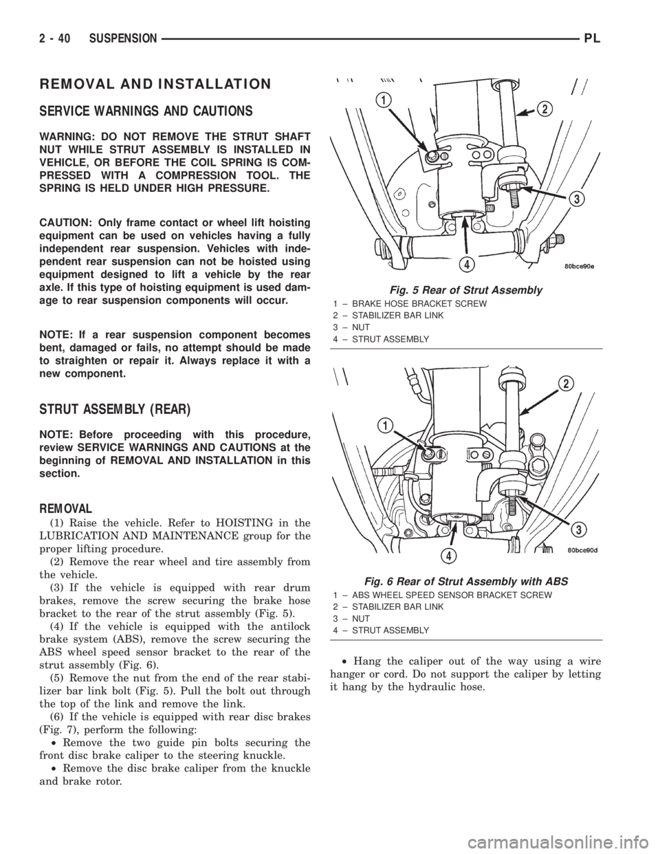
(3) If the vehicle is equipped with rear drum
brakes, remove the screw securing the brake hose
bracket to the rear of the strut assembly (Fig. 5).
(4) If the vehicle is equipped with the antilock
brake system (ABS), remove the screw securing the
ABS wheel speed sensor bracket to the rear of the
strut assembly (Fig. 6).
(5) Remove the nut from the end of the rear stabi-
lizer bar link bolt (Fig. 5). Pull the bolt out through
the top of the link and remove the link.
(6) If the vehicle is equipped with rear disc brakes
(Fig. 7), perform the following:
²Remove the two guide pin bolts securing the
front disc brake caliper to the steering knuckle.
²Remove the disc brake caliper from the knuckle
and brake rotor.²Hang the caliper out of the way using a wire
hanger or cord. Do not support the caliper by letting
it hang by the hydraulic hose.
Fig. 5 Rear of Strut Assembly
1 ± BRAKE HOSE BRACKET SCREW
2 ± STABILIZER BAR LINK
3 ± NUT
4 ± STRUT ASSEMBLY
Fig. 6 Rear of Strut Assembly with ABS
1 ± ABS WHEEL SPEED SENSOR BRACKET SCREW
2 ± STABILIZER BAR LINK
3 ± NUT
4 ± STRUT ASSEMBLY
2 - 40 SUSPENSIONPL
Page 59 of 1285
DISASSEMBLY
(1) If both struts are being serviced at the same
time, mark the coil spring and strut assembly accord-
ing to which side of the vehicle the strut was
removed from, and which strut the coil spring was
removed from.
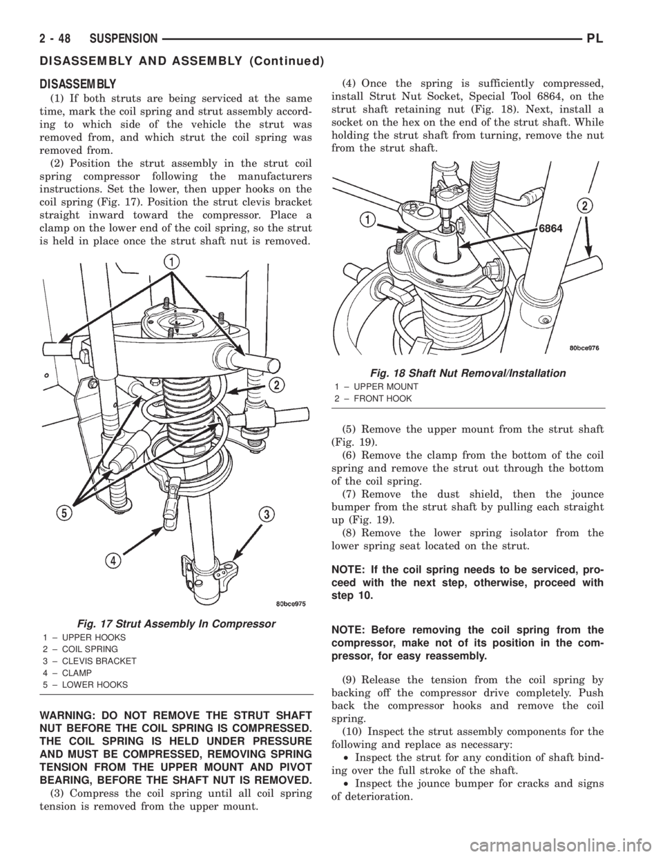
(2) Position the strut assembly in the strut coil
spring compressor following the manufacturers
instructions. Set the lower, then upper hooks on the
coil spring (Fig. 17). Position the strut clevis bracket
straight inward toward the compressor. Place a
clamp on the lower end of the coil spring, so the strut
is held in place once the strut shaft nut is removed.
WARNING: DO NOT REMOVE THE STRUT SHAFT
NUT BEFORE THE COIL SPRING IS COMPRESSED.
THE COIL SPRING IS HELD UNDER PRESSURE
AND MUST BE COMPRESSED, REMOVING SPRING
TENSION FROM THE UPPER MOUNT AND PIVOT
BEARING, BEFORE THE SHAFT NUT IS REMOVED.
(3) Compress the coil spring until all coil spring
tension is removed from the upper mount.(4) Once the spring is sufficiently compressed,
install Strut Nut Socket, Special Tool 6864, on the
strut shaft retaining nut (Fig. 18). Next, install a
socket on the hex on the end of the strut shaft. While
holding the strut shaft from turning, remove the nut
from the strut shaft.
(5) Remove the upper mount from the strut shaft
(Fig. 19).
(6) Remove the clamp from the bottom of the coil
spring and remove the strut out through the bottom
of the coil spring.
(7) Remove the dust shield, then the jounce
bumper from the strut shaft by pulling each straight
up (Fig. 19).
(8) Remove the lower spring isolator from the
lower spring seat located on the strut.
NOTE: If the coil spring needs to be serviced, pro-
ceed with the next step, otherwise, proceed with
step 10.
NOTE: Before removing the coil spring from the
compressor, make not of its position in the com-
pressor, for easy reassembly.
(9) Release the tension from the coil spring by
backing off the compressor drive completely. Push
back the compressor hooks and remove the coil
spring.
(10) Inspect the strut assembly components for the
following and replace as necessary:
²Inspect the strut for any condition of shaft bind-
ing over the full stroke of the shaft.
²Inspect the jounce bumper for cracks and signs
of deterioration.
Fig. 17 Strut Assembly In Compressor
1 ± UPPER HOOKS
2 ± COIL SPRING
3 ± CLEVIS BRACKET
4 ± CLAMP
5 ± LOWER HOOKS
Fig. 18 Shaft Nut Removal/Installation
1 ± UPPER MOUNT
2 ± FRONT HOOK
2 - 48 SUSPENSIONPL
DISASSEMBLY AND ASSEMBLY (Continued)