2000 DODGE NEON set clock
[x] Cancel search: set clockPage 198 of 1285
COOLING SYSTEMÐDRAINING
NOTE: Drain, flush, and fill the cooling system at
the mileage or time intervals specified in Group 0,
Lubrication and Maintenance. If the solution is dirty,
rusty, or contains a considerable amount of sedi-
ment; clean and flush with a reliable cooling system
cleaner. Care should be taken in disposing of the
used engine coolant from your vehicle. Check gov-
ernmental regulations for disposal of used engine
coolant.
Without removing radiator pressure cap and
with system not under pressure:
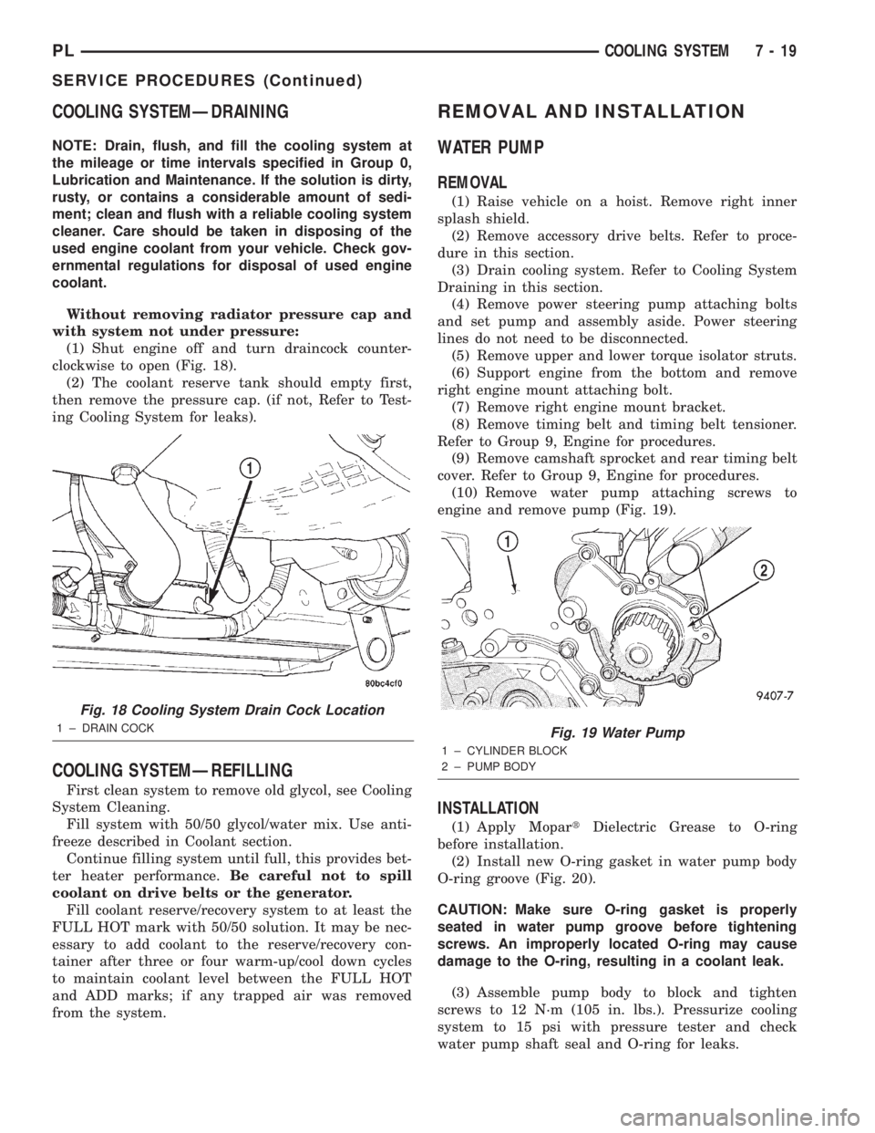
(1) Shut engine off and turn draincock counter-
clockwise to open (Fig. 18).
(2) The coolant reserve tank should empty first,
then remove the pressure cap. (if not, Refer to Test-
ing Cooling System for leaks).
COOLING SYSTEMÐREFILLING
First clean system to remove old glycol, see Cooling
System Cleaning.
Fill system with 50/50 glycol/water mix. Use anti-
freeze described in Coolant section.
Continue filling system until full, this provides bet-
ter heater performance.Be careful not to spill
coolant on drive belts or the generator.
Fill coolant reserve/recovery system to at least the
FULL HOT mark with 50/50 solution. It may be nec-
essary to add coolant to the reserve/recovery con-
tainer after three or four warm-up/cool down cycles
to maintain coolant level between the FULL HOT
and ADD marks; if any trapped air was removed
from the system.
REMOVAL AND INSTALLATION
WATER PUMP
REMOVAL
(1) Raise vehicle on a hoist. Remove right inner
splash shield.
(2) Remove accessory drive belts. Refer to proce-
dure in this section.
(3) Drain cooling system. Refer to Cooling System
Draining in this section.
(4) Remove power steering pump attaching bolts
and set pump and assembly aside. Power steering
lines do not need to be disconnected.
(5) Remove upper and lower torque isolator struts.
(6) Support engine from the bottom and remove
right engine mount attaching bolt.
(7) Remove right engine mount bracket.
(8) Remove timing belt and timing belt tensioner.
Refer to Group 9, Engine for procedures.
(9) Remove camshaft sprocket and rear timing belt
cover. Refer to Group 9, Engine for procedures.
(10) Remove water pump attaching screws to
engine and remove pump (Fig. 19).
INSTALLATION
(1) Apply MopartDielectric Grease to O-ring
before installation.
(2) Install new O-ring gasket in water pump body
O-ring groove (Fig. 20).
CAUTION: Make sure O-ring gasket is properly
seated in water pump groove before tightening
screws. An improperly located O-ring may cause
damage to the O-ring, resulting in a coolant leak.
(3) Assemble pump body to block and tighten
screws to 12 N´m (105 in. lbs.). Pressurize cooling
system to 15 psi with pressure tester and check
water pump shaft seal and O-ring for leaks.
Fig. 18 Cooling System Drain Cock Location
1 ± DRAIN COCKFig. 19 Water Pump
1 ± CYLINDER BLOCK
2 ± PUMP BODY
PLCOOLING SYSTEM 7 - 19
SERVICE PROCEDURES (Continued)
Page 253 of 1285
(6) Set base aside and remove base mount ring.
INSTALLATION
(1) Position mount ring to the instrument panel
and feed the wires through ring. Index the cap and
the mount ring with the index tab at 9 o'clock to the
key in the instrument panel. Install the ring.
(2) Connect wires to base. Orient base alignment
rib at 11 o'clock to mate the groove in mount ring at
the same location
(3) Push base into the bezel till it locks.
(4) Install cigar lighter cap and check operation of
element.
GLOVE BOX DOOR/BIN
REMOVAL
(1) Open front passenger door.
(2) Remove three glove box door hinge screws.
(3) Open glove box and remove assembly from
vehicle.
(4) Remove eight screws retaining glove box door
to bin assembly.
(5) Separate glove box door from bin and remove.
INSTALLATION
For installation, reverse the above procedures.
GLOVE BOX DOOR/BIN
REMOVAL
(1) Open front passenger door.
(2) Remove three glove box door hinge screws.
(3) Open glove box and remove assembly from
vehicle.
(4) Remove eight screws retaining glove box door
to bin assembly.(5) Separate glove box door from bin and remove.
INSTALLATION
For installation, reverse the above procedures.
GLOVE BOX SWITCH/LAMP
REMOVAL
(1) Disconnect and isolate the battery negative
cable (Fig. 6).
(2) Open the glove box and push the glove box
sides inward allowing the door bumpers to clear and
the box to tip forward.
(3) Reach inside the opening and squeeze the
lamp/switch retainers until they are disengage.
(4) Pull the switch/lamp rearward and remove it.
Replace the lamp. To replace the switch disconnect
wire and replace the switch.
INSTALLATION
For installation, reverse the above procedures.
INSTRUMENT CLUSTER
CAUTION: The Instrument Cluster MUST be stored
in a face up position or damage will occur to the
gauge operation.
REMOVAL
(1) Disconnect and isolate the battery negative
cable (Fig. 6).
(2) Remove both left and right A-Pillar trim covers.
(3) Remove the instrument panel top cover.
(4) Remove cluster bezel.
(5) Remove the four screws attaching cluster hous-
ing to the base panel.
(6) Pull the cluster rearward to disconnect from
base panel.
(7) Remove the cluster assembly.
INSTALLATION
For installation, reverse the above procedures.
INSTRUMENT CLUSTER BEZEL
REMOVAL
(1) Remove instrument panel top cover. Refer to
Instrument Panel Top Cover Removal and Installa-
tion in this section.
(2) Using a trim stick (special tool #C-4755), gently
pry up on the cluster bezel and remove from vehicle.
INSTALLATION
For installation, reverse the above procedures.
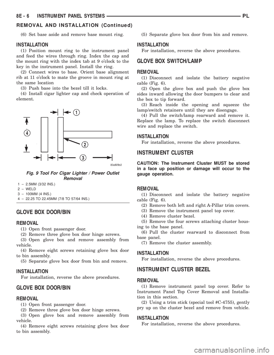
Fig. 9 Tool For Cigar Lighter / Power Outlet
Removal
1 ± 2.5MM (3/32 INS.)
2 ± WELD
3 ± 100MM (4 INS.)
4 ± 22.25 TO 22.45MM (7/8 TO 57/64 INS.)
8E - 6 INSTRUMENT PANEL SYSTEMSPL
REMOVAL AND INSTALLATION (Continued)
Page 270 of 1285
AUDIO SYSTEM
TABLE OF CONTENTS
page page
GENERAL INFORMATION
INTRODUCTION..........................1
DESCRIPTION AND OPERATION
INTERFERENCE ELIMINATION...............1
DIAGNOSIS AND TESTING
AUDIO DIAGNOSTIC TEST PROCEDURES......1
TESTING................................1
BENCH TEST FOR ANTENNA MALFUNCTION...7REMOVAL AND INSTALLATION
CD CHANGER............................7
FRONT DOOR SPEAKER....................8
INSTRUMENT PANEL SPEAKER(S)...........8
MAST and ANTENNA ASSEMBLY.............8
RADIO..................................9
REAR SHELF SPEAKER(S).................10
GENERAL INFORMATION
INTRODUCTION
Operating instructions for the factory installed
audio systems can be found in the Owner's Manual
provided with the vehicle.
The vehicles are equipped with an Interior (Igni-
tion Off Draw) fuse in the Power Distribution Center
located in the engine compartment. After the Interior
(IOD) fuse or battery has been disconnected the clock
will require resetting. The radio station presets have
a nonvolatile memory and will retain the preset sta-
tions after a battery disconnect.
The available radio options are:
²AM/FM Stereo Cassette w/Clock
²AM/FM/CD
²AM/FM Cassette w/CD Changer Controls and
Display
²CD/4 Disc Changer - In-Dash (used w/Radio CD
Changer Controls)
DESCRIPTION AND OPERATION
INTERFERENCE ELIMINATION
The radio utilizes a ground wire plugged on to a
blade terminal and is bolted to the radio chassis.
Both connector and terminal should be securely
attached. The engine has two separate ground straps
to suppress ignition noise which may interfere with
radio reception.
²Left engine mount clip on strap
²Engine to shock tower reinforcement
Inductive type spark plug cables in the high ten-
sion circuit of the ignition system complete the inter-
ference suppression. Faulty or deteriorated spark
plug wires should be replaced.
DIAGNOSIS AND TESTING
AUDIO DIAGNOSTIC TEST PROCEDURES
CAUTION: The CD player will only operate between
approximate temperatures of -23ÉC and +65ÉC (-10ÉF
and +145ÉF).
Whenever a radio malfunction occurs;
(1) First check FUSES:
(a) Power Distribution Center (PDC), Interior
lamp fuse, M1 - Radio Memory Feed
(b) Fuse Block:
(I) Fuse 12, Illumination in the fuse block
(II) Fuse 16, Ignition feed in the fuse block
NOTE: The vehicles are shipped with the INTERIOR
LAMP fuse disconnected.
(2) Verify, the radio wire harness are properly con-
nected before starting normal diagnosis and repair
procedures. Refer to Audio Diagnostic Charts and/or
Group 8W, Wiring Diagrams, Radio Section.
TESTING
The antenna has a short cable which connects into
the instrument panel harness. The connection is
made on the right side of the instrument panel.
Antenna performance may be tested by substitut-
ing a known good antenna. It is also possible to
check short or open circuits with an ohmmeter or
continuity light once the antenna cable is discon-
nected from the radio as follows:
(1) Continuity should be present between the
antenna mast and radio end pin of antenna cable
plug (Fig. 1).
(2) No continuity should be observed or a very
high resistance of several megohms between the
ground shell of the connector and radio end pin.
PLAUDIO SYSTEM 8F - 1
Page 485 of 1285

C2415C156C280C2MODULE CONTROL
POWERTRAIN
SPEED
CONTROL
SWITCH
SIGNAL
V37
20
RD/LG
V37
20
RD/LG
43
V32
20
YL/RD
V32
20
YL/RD
5C102
3
412
V36
20
TN/RDV35
20
LG/RD
V30
20
DB/RD
SERVO CONTROL
SPEED
VEHICLE
Z1
20
BK
Z1
18
BK
S112
3 2 140
VEHICLE
SPEED
CONTROL
SWITCH CLOCKSPRING
6
CLOCKSPRING
7
DUMP
SOLENOID SPEED
CONTROL
VENT
SOLENOID
CONTROL CONTROLSOLENOIDVACUUM CONTROLSPEED
BRAKE
LAMP
SWITCH
0 OFF
1 CANCEL
2 SET/COAST
3 RES/ACCEL
4 ON
C15C10415
VENT
SOLENOIDVACUUM
SOLENOID
G101G201
SUPPLYPOWER CONTROLSPEED
Z10
20
BK/TN
Z9
14
BK
S210(8W-15-3)(8W-30-13)
(8W-15-3)(8W-15-8) (8W-33-3)
(8W-33-3)(8W-33-3)
(8W-33-3)
(8W-15-8)
8W - 30 - 12 8W-30 FUEL/IGNITION SYSTEMPL
008W-10PLI03012
Page 909 of 1285
(25) Turn the key to OFF and remove the scan tool
from the vehicle.
(26) Test the operation of the horn, wipers and any
other functions that are steering column operated. If
applicable, reset the radio and the clock.
(27) If the steering column is a tilt column, verify
the tilt mechanism operates properly.
(28) Road test the vehicle to ensure proper opera-
tion of the steering system and the speed control sys-
tem.
STEERING COLUMN LOWER COUPLING
NOTE: Before proceeding with this removal and
installation procedure, review SERVICE WARNINGS
AND CAUTIONS at the beginning of REMOVAL AND
INSTALLATION in this section and in STEERING
GEAR.
REMOVAL
(1) Place the steering wheel in the STRAIGHT-
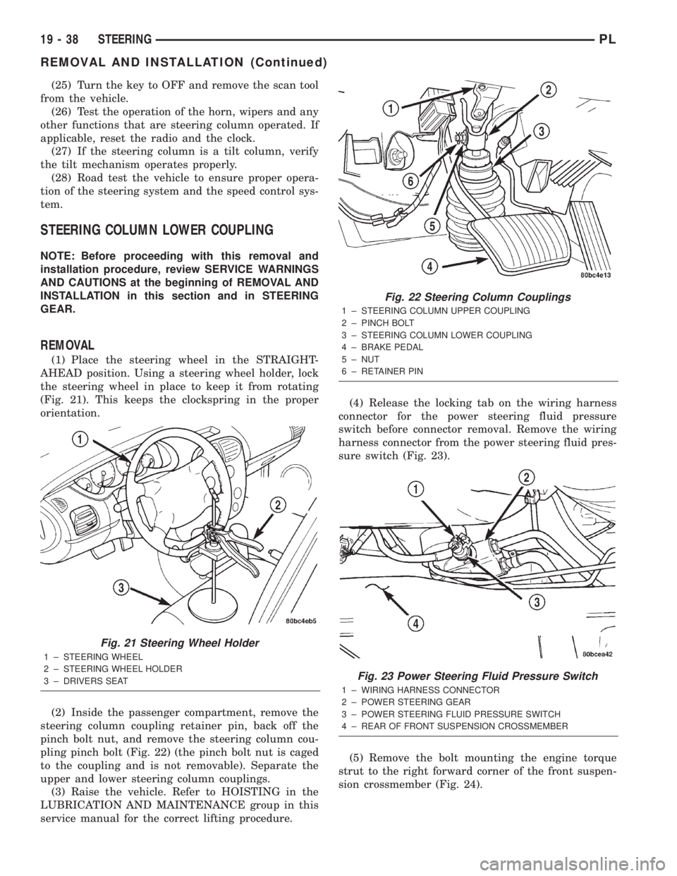
AHEAD position. Using a steering wheel holder, lock
the steering wheel in place to keep it from rotating
(Fig. 21). This keeps the clockspring in the proper
orientation.
(2) Inside the passenger compartment, remove the
steering column coupling retainer pin, back off the
pinch bolt nut, and remove the steering column cou-
pling pinch bolt (Fig. 22) (the pinch bolt nut is caged
to the coupling and is not removable). Separate the
upper and lower steering column couplings.
(3) Raise the vehicle. Refer to HOISTING in the
LUBRICATION AND MAINTENANCE group in this
service manual for the correct lifting procedure.(4) Release the locking tab on the wiring harness
connector for the power steering fluid pressure
switch before connector removal. Remove the wiring
harness connector from the power steering fluid pres-
sure switch (Fig. 23).
(5) Remove the bolt mounting the engine torque
strut to the right forward corner of the front suspen-
sion crossmember (Fig. 24).
Fig. 21 Steering Wheel Holder
1 ± STEERING WHEEL
2 ± STEERING WHEEL HOLDER
3 ± DRIVERS SEAT
Fig. 22 Steering Column Couplings
1 ± STEERING COLUMN UPPER COUPLING
2 ± PINCH BOLT
3 ± STEERING COLUMN LOWER COUPLING
4 ± BRAKE PEDAL
5 ± NUT
6 ± RETAINER PIN
Fig. 23 Power Steering Fluid Pressure Switch
1 ± WIRING HARNESS CONNECTOR
2 ± POWER STEERING GEAR
3 ± POWER STEERING FLUID PRESSURE SWITCH
4 ± REAR OF FRONT SUSPENSION CROSSMEMBER
19 - 38 STEERINGPL
REMOVAL AND INSTALLATION (Continued)
Page 954 of 1285
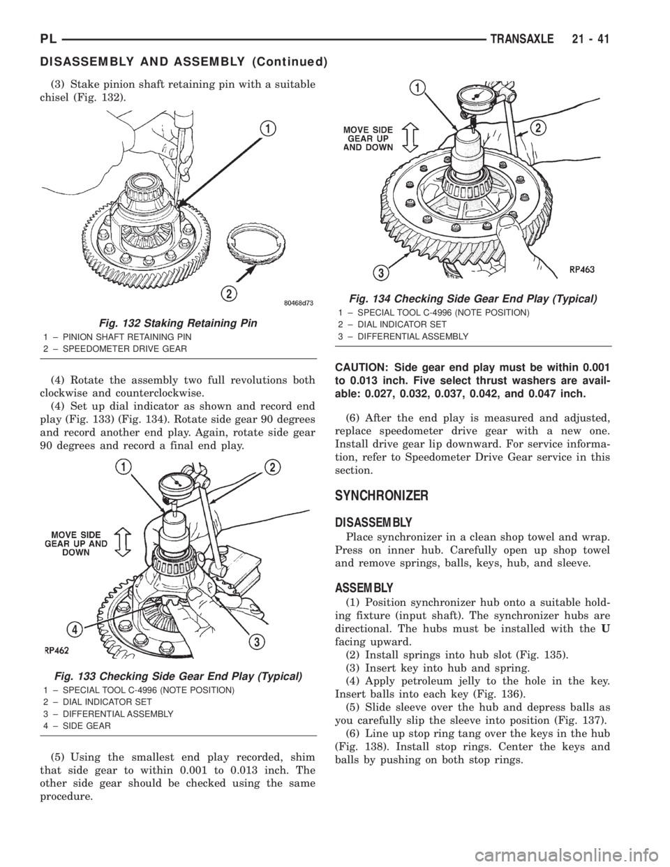
(3) Stake pinion shaft retaining pin with a suitable
chisel (Fig. 132).
(4) Rotate the assembly two full revolutions both
clockwise and counterclockwise.
(4) Set up dial indicator as shown and record end
play (Fig. 133) (Fig. 134). Rotate side gear 90 degrees
and record another end play. Again, rotate side gear
90 degrees and record a final end play.
(5) Using the smallest end play recorded, shim
that side gear to within 0.001 to 0.013 inch. The
other side gear should be checked using the same
procedure.CAUTION: Side gear end play must be within 0.001
to 0.013 inch. Five select thrust washers are avail-
able: 0.027, 0.032, 0.037, 0.042, and 0.047 inch.
(6) After the end play is measured and adjusted,
replace speedometer drive gear with a new one.
Install drive gear lip downward. For service informa-
tion, refer to Speedometer Drive Gear service in this
section.
SYNCHRONIZER
DISASSEMBLY
Place synchronizer in a clean shop towel and wrap.
Press on inner hub. Carefully open up shop towel
and remove springs, balls, keys, hub, and sleeve.
ASSEMBLY
(1) Position synchronizer hub onto a suitable hold-
ing fixture (input shaft). The synchronizer hubs are
directional. The hubs must be installed with theU
facing upward.
(2) Install springs into hub slot (Fig. 135).
(3) Insert key into hub and spring.
(4) Apply petroleum jelly to the hole in the key.
Insert balls into each key (Fig. 136).
(5) Slide sleeve over the hub and depress balls as
you carefully slip the sleeve into position (Fig. 137).
(6) Line up stop ring tang over the keys in the hub
(Fig. 138). Install stop rings. Center the keys and
balls by pushing on both stop rings.
Fig. 132 Staking Retaining Pin
1 ± PINION SHAFT RETAINING PIN
2 ± SPEEDOMETER DRIVE GEAR
Fig. 133 Checking Side Gear End Play (Typical)
1 ± SPECIAL TOOL C-4996 (NOTE POSITION)
2 ± DIAL INDICATOR SET
3 ± DIFFERENTIAL ASSEMBLY
4 ± SIDE GEAR
Fig. 134 Checking Side Gear End Play (Typical)
1 ± SPECIAL TOOL C-4996 (NOTE POSITION)
2 ± DIAL INDICATOR SET
3 ± DIFFERENTIAL ASSEMBLY
PLTRANSAXLE 21 - 41
DISASSEMBLY AND ASSEMBLY (Continued)
Page 963 of 1285
(10) Install center console assembly (Fig. 158). Ver-
ify that boot is not pinched at console opening before
tightening.
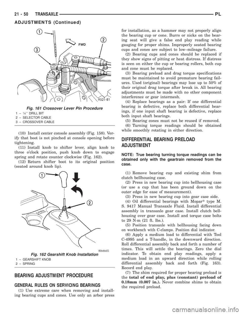
(11) Install knob to shifter lever, align knob to
three o'clock position, push knob down to engage
spring and rotate counter clockwise (Fig. 162).
(12) Return shifter boot to its original position
(seated around knob lip).
BEARING ADJUSTMENT PROCEDURE
GENERAL RULES ON SERVICING BEARINGS
(1) Use extreme care when removing and install-
ing bearing cups and cones. Use only an arbor pressfor installation, as a hammer may not properly align
the bearing cup or cone. Burrs or nicks on the bear-
ing seat will give a false end play reading while
gauging for proper shims. Improperly seated bearing
cups and cones are subject to low±mileage failure.
(2) Bearing cups and cones should be replaced if
they show signs of pitting or heat distress. If distress
is seen on either the cup or bearing rollers, both cup
and cone must be replaced.
(3) Bearing preload and drag torque specifications
must be maintained to avoid premature bearing fail-
ures. Used (original) bearings may lose up to 50% of
their original drag torque after break in. All bearing
adjustments must be made with no other component
interference or gear intermesh.
(4) Replace bearings as a pair: If one differential
bearing is defective, replace both differential bear-
ings, if one input shaft bearing is defective, replace
both input shaft bearings.
(5) Bearing cones must not be reused if removed.
(6) Turning torque readings should be obtained
while smoothly rotating in either direction.
DIFFERENTIAL BEARING PRELOAD
ADJUSTMENT
NOTE: True bearing turning torque readings can be
obtained only with the geartrain removed from the
case.
(1) Remove bearing cup and existing shim from
clutch bellhousing case.
(2) Press in new bearing cup into bellhousing case
(or use a cup that has been ground down on the
outer edge for ease of measurement).
(3) Press in new bearing cup into gear case side.
(4) Oil differential bearings with Moparttype M.
S. 9417 Manual Transaxle Fluid. Install differential
assembly in transaxle gear case. Install clutch bell-
housing over gear case. Install and torque case bolts
to 29 N´m (21 ft. lbs.).
(5)
Position transaxle with bellhousing facing down
on workbench with C-clamps. Position dial indicator.
(6) Apply a medium load to differential with Tool
C-4995 and a T-handle, in the downward direction.
Roll differential assembly back and forth a number of
times. This will settle the bearings. Zero the dial
indicator. To obtain end play readings, apply a
medium load in an upward direction while rolling
differential assembly back and forth (Fig. 163).
Record end play.
(7) The shim required for proper bearing preload is
thetotal of end play, plus (constant) preload of
0.18mm (0.007 in.).Never combine shims to obtain
the required preload.
Fig. 161 Crossover Lever Pin Procedure
1±1¤488DRILL BIT
2 ± SELECTOR CABLE
3 ± CROSSOVER CABLE
Fig. 162 Gearshift Knob Installation
1 ± GEARSHIFT KNOB
2 ± SPRING
21 - 50 TRANSAXLEPL
ADJUSTMENTS (Continued)
Page 981 of 1285
TEST TWO (SELECTOR IN 2)
(1) Attach one gauge to line pressure port, and tee
another gauge into lower cooler line fitting. This will
allow lubrication pressure readings to be taken..
(2) Operate engine at 1000 rpm for test.
(3) Move selector lever on transaxle one detent for-
ward from full rearward position. This is selector 2
position.
(4) Read pressures on both gauges as throttle lever
on transaxle is moved from full clockwise position to
full counterclockwise position.
(5) Line pressure should read 52 to 58 psi with
throttle lever clockwise. Pressure should gradually
increase to 80 to 88 psi. as lever is moved counter-
clockwise.
(6) Lubrication pressure should be 10 to 25 psi
with lever clockwise and 10 to 35 psi with lever at
full counterclockwise.
(7) This tests pump output, pressure regulation,
and condition of rear clutch and lubrication hydraulic
circuits.
TEST THREE (SELECTOR IN D)
(1) Attach gauges to line and kickdown release
ports.
(2) Operate engine at 1600 rpm for test.
(3) Move selector lever on transaxle two detents
forward from full rearward position. This is selector
D position.
(4) Read pressures on both gauges as throttle lever
on transaxle is moved from full clockwise to the full
counterclockwise position.
(5) Line pressure should read 52 to 58 psi with
throttle lever clockwise. Pressure should gradually
increase to 80 to 88 psi. as lever is moved counter-
clockwise.
(6) Kickdown release is pressurized only in direct
drive and should be same as line pressure within 3
psi, up to kickdown point.
(7) This tests pump output, pressure regulation,
and condition of rear clutch, front clutch, and
hydraulic circuits.
TEST FOUR (SELECTOR IN REVERSE)
(1) Attach 300 psi gauge to low-reverse port.
(2) Operate engine at 1600 rpm for test.
(3) Move selector lever on transaxle four detents
forward from full rearward position. This is selector
R position.
(4) Low/reverse pressure should read 180 to 220
psi with throttle lever clockwise. Pressure should
gradually increase to 260 to 300 psi. as lever is
moved counterclockwise.
(5) This tests pump output, pressure regulation,
and condition of front clutch and rear servo hydraulic
circuits.(6) Move selector lever on transaxle to D position
to check that low/reverse pressure drops to zero.
(7) This tests for leakage into rear servo, due to
case porosity, which can cause reverse band burn out.
TEST RESULT INDICATIONS
(1) If proper line pressure, minimum to maximum,
is found in any one test, the pump and pressure reg-
ulator are working properly.
(2) Low pressure in D, 1, and 2 but correct pres-
sure in R, indicates rear clutch circuit leakage.
(3) Low pressure in D and R, but correct pressure
in 1 indicates front clutch circuit leakage.
(4) Low pressure in R and 1, but correct pressure
in 2 indicates rear servo circuit leakage.
(5) Low line pressure in all positions indicates a
defective pump, a clogged filter, or a stuck pressure
regulator valve.
GOVERNOR PRESSURE
Test only if transaxle shifts at wrong vehicle
speeds when throttle cable is correctly adjusted.
(1) Connect a 0-150 psi pressure gauge to governor
pressure take-off point. It is located at lower right
side of case, below differential cover.
(2) Operate transaxle in third gear to read pres-
sures. The governor pressure should respond
smoothly to changes in mph and should return to 0
to 3 psi when vehicle is stopped. High pressure
(above 3 psi) at standstill will prevent the transaxle
from downshifting.
THROTTLE PRESSURE
No gauge port is provided for throttle pressure.
Incorrect throttle pressure should be suspected if
part throttle upshift speeds are either delayed or
occur too early in relation to vehicle speed. Engine
runaway on shifts can also be an indicator of low
throttle pressure setting, or misadjusted throttle
cable.
In no case should throttle pressure be adjusted
until the transaxle throttle cable adjustment has
been verified to be correct.
CLUTCH AND SERVO AIR PRESSURE TESTS
A no±drive condition might exist even with correct
fluid pressure, because of inoperative clutches or
bands. The inoperative units, clutches, bands, and
servos can be located through a series of tests. This
is done by substituting air pressure for fluid pressure
(Fig. 7).
The front and rear clutches, kickdown servo, and
low/reverse servo can be tested by applying air pres-
sure to their respective passages. To make air pres-
sure tests, proceed as follows:
21 - 68 TRANSAXLEPL
DIAGNOSIS AND TESTING (Continued)