2000 DODGE NEON set clock
[x] Cancel search: set clockPage 1051 of 1285

BAND ADJUSTMENT
KICKDOWN BAND (FRONT)
The kickdown band adjusting screw is located on
left side (top front) of the transaxle case.
(1) Loosen locknut and back±off nut approximately
five turns. Test adjusting screw for free turning in
the transaxle case.
(2) Using wrench, tighten adjusting screw to 8
N´m (72 in. lbs.).
(3) Back±off adjusting screw the number of turns
listed in Specifications. Hold adjusting screw in this
position and tighten locknut to 47 N´m (35ft. lbs.)
LOW/REVERSE BAND (REAR)
To adjust low/reverse band, proceed as follows:
(1) Loosen and back off locknut approximately five
turns.
(2) Using an inch-pound torque wrench, tighten
adjusting screw to 5 N´m (41 in. lbs.) true torque.
(3) Back±off adjusting screw the number of turns
listed under Specifications. A chart is located at the
rear of this section.
(4) Tighten locknut to 14 N´m (10 ft. lbs.).
HYDRAULIC CONTROL PRESSURE
ADJUSTMENTS
LINE PRESSURE
An incorrect throttle pressure setting will cause
incorrect line pressure readings even though line
pressure adjustment is correct. Always inspect andcorrect throttle pressure adjustment before adjusting
the line pressure.
The approximate adjustment for line pressure is
1-5/16 inches, measured from valve body to inner
edge of adjusting nut. However, due to manufactur-
ing tolerances, the adjustment can be varied to
obtain specified line pressure.
The adjusting screw may be turned with an Allen
wrench. One complete turn of adjusting screw
changes closed throttle line pressure approximately
1-2/3 psi. Turning adjusting screw counterclockwise
increases pressure, and clockwise decreases pressure.
THROTTLE PRESSURE
Throttle pressures cannot be tested accurately;
therefore, the adjustment should be measured if a
malfunction is evident.
(1) Insert gauge pin of Tool C-3763 between the
throttle lever cam and kickdown valve.
(2) By pushing in on tool, compress kickdown
valve against its spring so throttle valve is com-
pletely bottomed inside the valve body.
(3) While compressing spring, turn throttle lever
stop screw with adapter C-4553. Turn until head of
screw touches throttle lever tang, with throttle lever
cam touching tool and throttle valve bottomed. Be
sure adjustment is made with spring fully com-
pressed and valve bottomed in the valve body.
BEARING ADJUSTMENT PROCEDURES
(1) Take extreme care when removing and install-
ing bearing cups and cones.Use only an arbor
press for installation, as a hammer may not
properly align the bearing cup or cone.Burrs or
nicks on the bearing seat will give a false end play
reading, while gauging for proper shims. Improperly
seated bearing cup and cones are subject to low-mile-
age failure.
(2) Bearing cups and cones should be replaced if
they show signs of pitting or heat distress.
(3) If distress is seen on either the cup or bearing
rollers, both cup and cone must be replaced.
NOTE: Bearing end play and drag torque specifica-
tions must be maintained to avoid premature bear-
ing failures.
(4) Used (original) bearing may lose up to 50 per-
cent of the original drag torque after break-in.
NOTE: All bearing adjustments must be made with
no other component interference or gear inter-
mesh, except the transfer gear bearing.
(5) Refer to the conversion chart in specifications
to convert inches to millimeter measurements. Refer
to bearing shim chart for proper shim thicknesses.
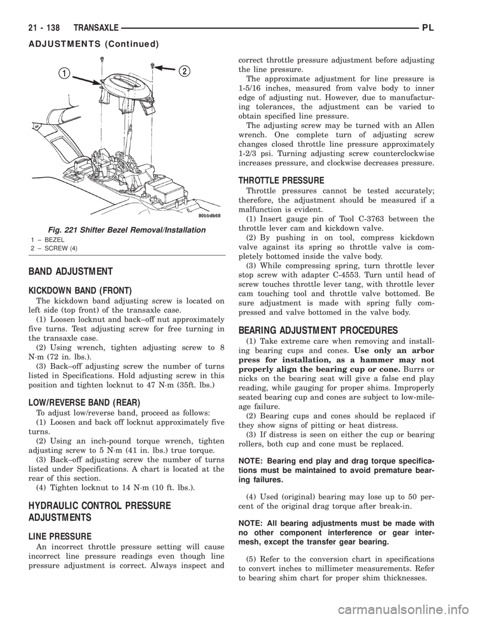
Fig. 221 Shifter Bezel Removal/Installation
1 ± BEZEL
2 ± SCREW (4)
21 - 138 TRANSAXLEPL
ADJUSTMENTS (Continued)
Page 1105 of 1285

Immediately after a cold start, between predeter-
mined temperature thresholds limits, the three port
solenoid is briefly energized. This initializes the
pump by drawing air into the pump cavity and also
closes the vent seal. During non test conditions the
vent seal is held open by the pump diaphragm
assembly which pushes it open at the full travel posi-
tion. The vent seal will remain closed while the
pump is cycling due to the reed switch triggering of
the three port solenoid that prevents the diaphragm
assembly from reaching full travel. After the brief
initialization period, the solenoid is de-energized
allowing atmospheric pressure to enter the pump
cavity, thus permitting the spring to drive the dia-
phragm which forces air out of the pump cavity and
into the vent system. When the solenoid is energized
and de energized, the cycle is repeated creating flow
in typical diaphragm pump fashion. The pump is con-
trolled in 2 modes:
Pump Mode:The pump is cycled at a fixed rate to
achieve a rapid pressure build in order to shorten the
overall test length.
Test Mode:The solenoid is energized with a fixed
duration pulse. Subsequent fixed pulses occur when
the diaphragm reaches the Switch closure point.
The spring in the pump is set so that the system
will achieve an equalized pressure of about 7.5º H20.
The cycle rate of pump strokes is quite rapid as the
system begins to pump up to this pressure. As the
pressure increases, the cycle rate starts to drop off. If
there is no leak in the system, the pump would even-
tually stop pumping at the equalized pressure. If
there is a leak, it will continue to pump at a rate rep-
resentative of the flow characteristic of the size of the
leak. From this information we can determine if the
leak is larger than the required detection limit (cur-
rently set at.040º orifice by CARB). If a leak is
revealed during the leak test portion of the test, the
test is terminated at the end of the test mode and no
further system checks will be performed.
After passing the leak detection phase of the test,
system pressure is maintained by turning on the
LDP's solenoid until the purge system is activated.
Purge activation in effect creates a leak. The cycle
rate is again interrogated and when it increases due
to the flow through the purge system, the leak check
portion of the diagnostic is complete.
The canister vent valve will unseal the system
after completion of the test sequence as the pump
diaphragm assembly moves to the full travel position.
Evaporative system functionality will be verified by
using the stricter evap purge flow monitor. At an
appropriate warm idle the LDP will be energized to
seal the canister vent. The purge flow will be clocked
up from some small value in an attempt to see a
shift in the 02 control system. If fuel vapor, indicatedby a shift in the 02 control, is present the test is
passed. If not, it is assumed that the purge system is
not functioning in some respect. The LDP is again
turned off and the test is ended.
Enabling Conditions for Systems with LDP
²Ambient Air Temperature
²Barometric Pressure
²Fuel level
²Engine Temperature
²No stalling
²Battery voltage
NON-LDP VEHICLESÐOn a vehicle without an
EVAP leak detection pump system, changes in short
term memory and movement in target IAC at idle or
idle speed change, are used to monitor the system.
There are two stages for this test.
Stage OneÐStage one is a non-intrusive test.
The PCM compares adaptive memory values between
purge and purge-free cells. The PCM uses these val-
ues to determine the amount of fuel vapors entering
the system. If the difference between the cells
exceeds a predetermined value, the test passes. If
not, then the monitor advances to state two.
Stage TwoÐOnce the enabling conditions are
met, the PCM de-energizes the Duty Cycle Purge
(DCP) solenoid. The PCM then waits until engine
RPM, Short Term Compensation and Idle Air Control
have all stabilized. Once stable, the PCM increments
the DCP solenoid cycle rate approximately 6% every
8 engine revolutions. If during the test any one of
three conditions occur before the DCP cycle reaches
100%, the EVAP system is considered to be opera-
tional and the test passes. These conditions are as
follows:
²RPM rises by a predetermined amount
²Short Term drops by a predetermined amount
²Idle Air Control closes by a predetermined
amount
When none of the previous conditions occur, the
test fails and the PCM increments a counter by one.
When the PCM runs the test three times during a
trip, and the counter has been incremented to three,
the monitor fails and a Freeze Frame is stored.
Enabling Conditions (Stage Two)ÐThe follow-
ing conditions must be met to enable the EVAP Mon-
itor (without LDP)
²Ambient Air Temperature
²Barometric Pressure
²Fuel level
²Engine Temperature
²Engine run time
²RPM stable
²MAP
²Generator, radiator fans, A/C clutch
Pending Conditions-With or Without LDPÐ
The EVAP Monitor is suspended and does not run,
25 - 18 EMISSION CONTROL SYSTEMSPL
DESCRIPTION AND OPERATION (Continued)
Page 1238 of 1285

SIDE WINDOW DEMISTERS
The demisters direct air from the unit housing
through the outlets located on the top corners of the
instrument panel. The demisters operate when the
mode selector is anywhere between floor and defrost
settings. Some air may be noticeable from the demis-
ter outlets when the mode selector is in the bilevel to
floor positions.
SYSTEM AIRFLOW
The system pulls outside (ambient) air through the
cowl opening at the base of the windshield. Then it
goes into the plenum chamber above the unit hous-
ing. On air conditioned vehicles, the air passes
through the evaporator. Air flow can be directed
either through or around the heater core. This is
done by adjusting the blend-air door with the TEMP
control on the instrument panel. The air flow can
then be directed from the panel, floor and defrost
outlets in various combinations using the mode selec-
tor. There are 17 different mode selections possible.
Air flow velocity can be adjusted with the blower
speed selector switch on the instrument panel.
On A/C equipped vehicles the ambient air intake
can be controlled by opening and closing the recircu-
lating air door. When placed in RECIRC, air that is
inside vehicle is removed continuously and recircu-
lated through unit housing. Ambient air cannot be
controlled on vehicles without A/C. The system uses
outside air at all times.
The air conditioning compressor can be engaged by
turning the fan switch counterclockwise from the off
position. It can also be engaged by placing the mode
control in the mix to defrost positions. This will
remove heat and humidity from the air before it is
directed through or around the heater core.
SYSTEM OIL LEVEL
It is important to have the correct amount of oil in
the A/C system to ensure proper lubrication of the
compressor. Too little oil will result in damage to the
compressor. Too much oil will reduce the cooling
capacity of the system and consequently result in
higher discharge air temperatures.
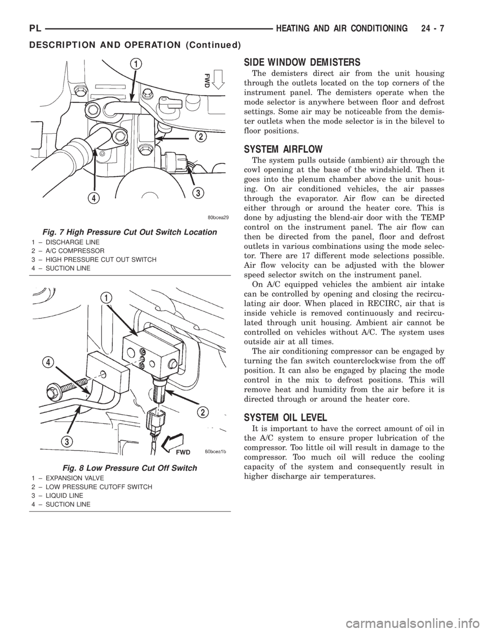
Fig. 7 High Pressure Cut Out Switch Location
1 ± DISCHARGE LINE
2 ± A/C COMPRESSOR
3 ± HIGH PRESSURE CUT OUT SWITCH
4 ± SUCTION LINE
Fig. 8 Low Pressure Cut Off Switch
1 ± EXPANSION VALVE
2 ± LOW PRESSURE CUTOFF SWITCH
3 ± LIQUID LINE
4 ± SUCTION LINE
PLHEATING AND AIR CONDITIONING 24 - 7
DESCRIPTION AND OPERATION (Continued)