2000 DODGE NEON exhaust
[x] Cancel search: exhaustPage 1 of 1285

GROUP TAB LOCATORINIntroductionINaIntroduction0Lubrication and Maintenance2Suspension3Differential and Driveline5Brakes6Clutch7Cooling8ABattery8BStarting8CCharging System8DIgnition System8EInstrument Panel and Systems8EaInstrument Panel and Systems8FAudio System8GHorns8HVehicle Speed Control System8JTurn Signal and Flashers8KWindshield Wipers and Washers8LLamps8LaLamps8MRestraint System8NElectrically Heated Systems8OPower Distribution Systems8PPower Door Locks8QImmobilizer System8SPower Windows8TPower Mirrors8TaPower Mirrors8UChime Warning/Reminder System8WWiring Diagrams - LHD and RHD9Engine11Exhaust System13Frame and Bumpers14Fuel System19Steering21Transaxle22Tires and Wheels23Body24Heating and Air Conditioning24aHeating and Air Conditioning25Emission Control Systems
Page 4 of 1285
MAINTENANCE SCHEDULES
TABLE OF CONTENTS
page page
DESCRIPTION AND OPERATION
MAINTENANCE SCHEDULES................3
SPECIFICATIONS
UNSCHEDULED INSPECTION................3SCHEDULE ± A...........................3
SCHEDULE ± B...........................4
DESCRIPTION AND OPERATION
MAINTENANCE SCHEDULES
There are two maintenance schedules that show
proper service for your vehicle.
First is Schedule ±A. It lists all the scheduled
maintenance to be performed under ªnormalº operat-
ing conditions.
Second is Schedule ±B. It is a schedule for vehi-
cles that are operated under the following conditions:
²Frequent short trip driving less than 5 miles (8
km)
²Frequent driving in dusty conditions
²Extensive idling
²More than 50% of the driving is at sustained
high speeds during hot weather, above 90É F (32É C)
SPECIFICATIONS
UNSCHEDULED INSPECTION
At Each Stop For Fuel
²Check engine oil level and add as required.
²Check windshield washer solvent and add as
required.
Once A Month
²Check tire pressure and look for unusual wear
or damage.
²Inspect the battery and clean and tighten termi-
nals as required.
²Check fluid levels of coolant reservoir, brake
master cylinder, power steering and transmission.
Add fluid as required.
²Check all lights and all other electrical items for
correct operation.
At Each Oil Change
²Inspect the exhaust system.
²Inspect brake hoses.
²Inspect the CV joints and front suspension com-
ponent boots and seals.²Rotate the tires at each oil change interval
shown on Schedule ± A (7,500 miles - 12 000 km) or
every other interval on Schedule ± B (6,000 miles -
10 000 km).
²Check the engine coolant level, hoses, and
clamps.
If mileage is less than 7,500 miles (12 000 km)
yearly, replace the engine oil filter at each oil change.
EMISSION CONTROL SYSTEM MAINTENANCE
The scheduled emission maintenance listed inbold
typeon the Maintenance Schedules, must be done at
the mileage specified to assure the continued proper
functioning of the emission control system. These,
and all other maintenance services included in this
manual, should be done to provide the best vehicle
performance and reliability. More frequent mainte-
nance may be needed for vehicles in severe operating
conditions such as dusty areas and very short trip
driving.
FLUID FILL POINTS AND LUBRICATION
LOCATIONS
The fluid fill/check locations and lubrication loca-
tions are located in each applicable group.
SCHEDULE ± A
7,500 Miles (12 000 km) or at 6 months
²Change the engine oil.
²Replace the engine oil filter.
15,000 Miles (24 000 km) or at 12 months
²Change the engine oil.
²Replace the engine oil filter.
²Adjust the drive belt tension.
22,500 Miles (36 000 km) or at 18 months
²Change the engine oil.
²Replace the engine oil filter.
²Inspect the front brake pads and rear brake lin-
ings.
PLLUBRICATION AND MAINTENANCE 0 - 3
Page 9 of 1285
onds, stop cranking engine and allow starter to cool
(15 minutes), before cranking again.
DISCONNECT CABLE CLAMPS AS FOLLOWS:
²Disconnect BLACK cable clamp from engine
ground on disabled vehicle.
²When using a Booster vehicle, disconnect
BLACK cable clamp from battery negative terminal.
Disconnect RED cable clamp from battery positive
terminal.
²Disconnect RED cable clamp from battery posi-
tive terminal on disabled vehicle.
TOWING RECOMMENDATIONS
WARNING: DO NOT ALLOW TOWING ATTACHMENT
DEVICES TO CONTACT THE FUEL TANK OR LINES,
FUEL LEAK CAN RESULT. DO NOT LIFT OR TOW
VEHICLE BY FRONT OR REAR BUMPER, OR
BUMPER ENERGY ABSORBER UNITS. DO NOT
VENTURE UNDER A LIFTED VEHICLE IF NOT SUP-
PORTED PROPERLY ON SAFETY STANDS. DO NOT
ALLOW PASSENGERS TO RIDE IN A TOWED VEHI-
CLE. USE A SAFETY CHAIN THAT IS INDEPENDENT
FROM THE TOWING ATTACHMENT DEVICE.
CAUTION: Do not damage brake lines, exhaust sys-
tem, shock absorbers, sway bars, or any other
under vehicle components when attaching towing
device to vehicle. Do not attach towing device to
front or rear suspension components. Do notsecure vehicle to towing device by the use of front
or rear suspension or steering components.
Remove or secure loose or protruding objects from
a damaged vehicle before towing. Refer to state and
local rules and regulations before towing a vehicle.
Do not allow weight of towed vehicle to bear on
lower fascia, air dams, or spoilers.
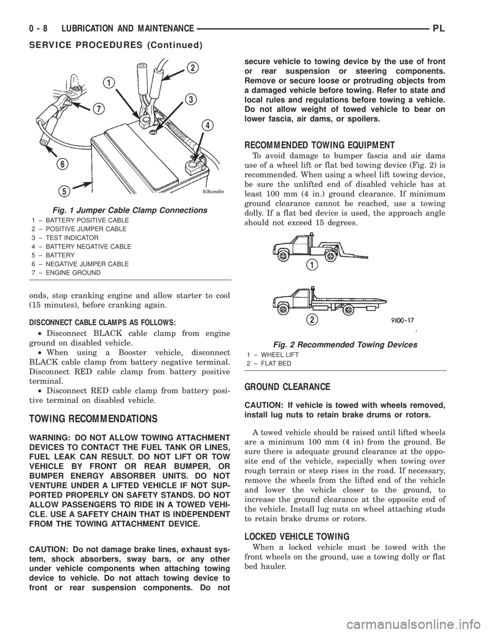
RECOMMENDED TOWING EQUIPMENT
To avoid damage to bumper fascia and air dams
use of a wheel lift or flat bed towing device (Fig. 2) is
recommended. When using a wheel lift towing device,
be sure the unlifted end of disabled vehicle has at
least 100 mm (4 in.) ground clearance. If minimum
ground clearance cannot be reached, use a towing
dolly. If a flat bed device is used, the approach angle
should not exceed 15 degrees.
GROUND CLEARANCE
CAUTION: If vehicle is towed with wheels removed,
install lug nuts to retain brake drums or rotors.
A towed vehicle should be raised until lifted wheels
are a minimum 100 mm (4 in) from the ground. Be
sure there is adequate ground clearance at the oppo-
site end of the vehicle, especially when towing over
rough terrain or steep rises in the road. If necessary,
remove the wheels from the lifted end of the vehicle
and lower the vehicle closer to the ground, to
increase the ground clearance at the opposite end of
the vehicle. Install lug nuts on wheel attaching studs
to retain brake drums or rotors.
LOCKED VEHICLE TOWING
When a locked vehicle must be towed with the
front wheels on the ground, use a towing dolly or flat
bed hauler.
Fig. 1 Jumper Cable Clamp Connections
1 ± BATTERY POSITIVE CABLE
2 ± POSITIVE JUMPER CABLE
3 ± TEST INDICATOR
4 ± BATTERY NEGATIVE CABLE
5 ± BATTERY
6 ± NEGATIVE JUMPER CABLE
7 ± ENGINE GROUND
Fig. 2 Recommended Towing Devices
1 ± WHEEL LIFT
2 ± FLAT BED
0 - 8 LUBRICATION AND MAINTENANCEPL
SERVICE PROCEDURES (Continued)
Page 181 of 1285
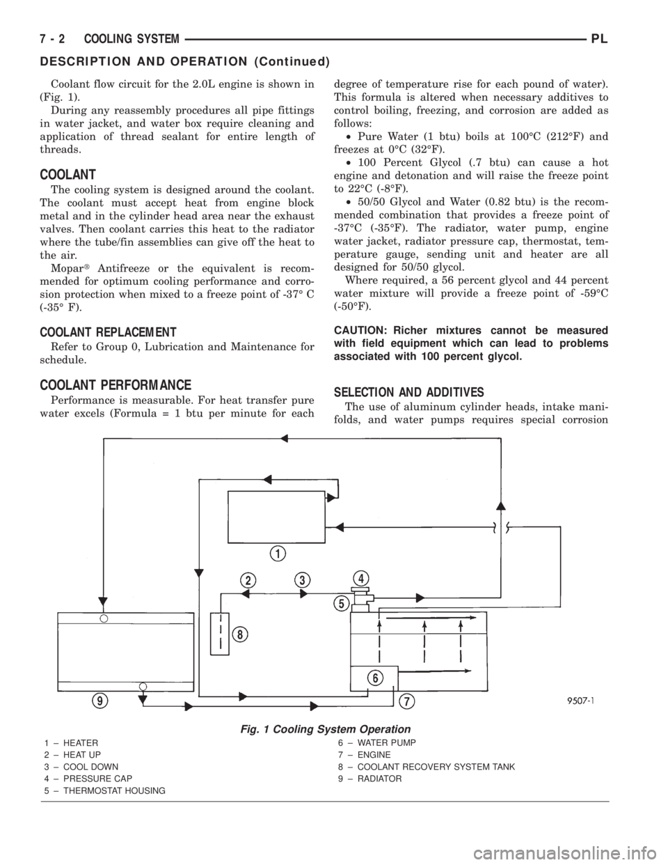
Coolant flow circuit for the 2.0L engine is shown in
(Fig. 1).
During any reassembly procedures all pipe fittings
in water jacket, and water box require cleaning and
application of thread sealant for entire length of
threads.
COOLANT
The cooling system is designed around the coolant.
The coolant must accept heat from engine block
metal and in the cylinder head area near the exhaust
valves. Then coolant carries this heat to the radiator
where the tube/fin assemblies can give off the heat to
the air.
MopartAntifreeze or the equivalent is recom-
mended for optimum cooling performance and corro-
sion protection when mixed to a freeze point of -37É C
(-35É F).
COOLANT REPLACEMENT
Refer to Group 0, Lubrication and Maintenance for
schedule.
COOLANT PERFORMANCE
Performance is measurable. For heat transfer pure
water excels (Formula = 1 btu per minute for eachdegree of temperature rise for each pound of water).
This formula is altered when necessary additives to
control boiling, freezing, and corrosion are added as
follows:
²Pure Water (1 btu) boils at 100ÉC (212ÉF) and
freezes at 0ÉC (32ÉF).
²100 Percent Glycol (.7 btu) can cause a hot
engine and detonation and will raise the freeze point
to 22ÉC (-8ÉF).
²50/50 Glycol and Water (0.82 btu) is the recom-
mended combination that provides a freeze point of
-37ÉC (-35ÉF). The radiator, water pump, engine
water jacket, radiator pressure cap, thermostat, tem-
perature gauge, sending unit and heater are all
designed for 50/50 glycol.
Where required, a 56 percent glycol and 44 percent
water mixture will provide a freeze point of -59ÉC
(-50ÉF).
CAUTION: Richer mixtures cannot be measured
with field equipment which can lead to problems
associated with 100 percent glycol.SELECTION AND ADDITIVES
The use of aluminum cylinder heads, intake mani-
folds, and water pumps requires special corrosion
Fig. 1 Cooling System Operation
1 ± HEATER
2 ± HEAT UP
3 ± COOL DOWN
4 ± PRESSURE CAP
5 ± THERMOSTAT HOUSING6 ± WATER PUMP
7 ± ENGINE
8 ± COOLANT RECOVERY SYSTEM TANK
9 ± RADIATOR
7 - 2 COOLING SYSTEMPL
DESCRIPTION AND OPERATION (Continued)
Page 185 of 1285
AUTOMATIC TRANSMISSION OIL COOLER
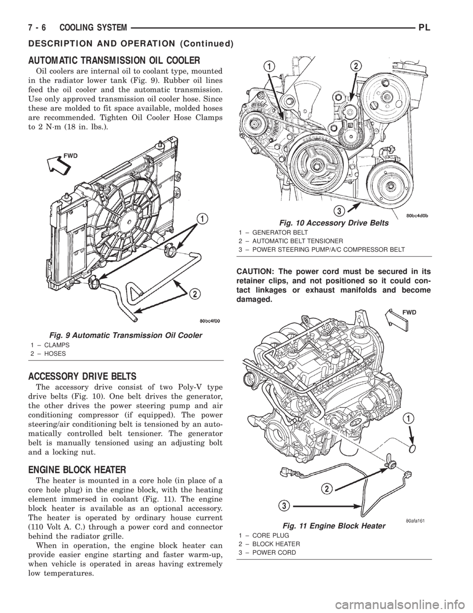
Oil coolers are internal oil to coolant type, mounted
in the radiator lower tank (Fig. 9). Rubber oil lines
feed the oil cooler and the automatic transmission.
Use only approved transmission oil cooler hose. Since
these are molded to fit space available, molded hoses
are recommended. Tighten Oil Cooler Hose Clamps
to 2 N´m (18 in. lbs.).
ACCESSORY DRIVE BELTS
The accessory drive consist of two Poly-V type
drive belts (Fig. 10). One belt drives the generator,
the other drives the power steering pump and air
conditioning compressor (if equipped). The power
steering/air conditioning belt is tensioned by an auto-
matically controlled belt tensioner. The generator
belt is manually tensioned using an adjusting bolt
and a locking nut.
ENGINE BLOCK HEATER
The heater is mounted in a core hole (in place of a
core hole plug) in the engine block, with the heating
element immersed in coolant (Fig. 11). The engine
block heater is available as an optional accessory.
The heater is operated by ordinary house current
(110 Volt A. C.) through a power cord and connector
behind the radiator grille.
When in operation, the engine block heater can
provide easier engine starting and faster warm-up,
when vehicle is operated in areas having extremely
low temperatures.CAUTION: The power cord must be secured in its
retainer clips, and not positioned so it could con-
tact linkages or exhaust manifolds and become
damaged.
Fig. 9 Automatic Transmission Oil Cooler
1 ± CLAMPS
2 ± HOSES
Fig. 10 Accessory Drive Belts
1 ± GENERATOR BELT
2 ± AUTOMATIC BELT TENSIONER
3 ± POWER STEERING PUMP/A/C COMPRESSOR BELT
Fig. 11 Engine Block Heater
1 ± CORE PLUG
2 ± BLOCK HEATER
3 ± POWER CORD
7 - 6 COOLING SYSTEMPL
DESCRIPTION AND OPERATION (Continued)
Page 188 of 1285
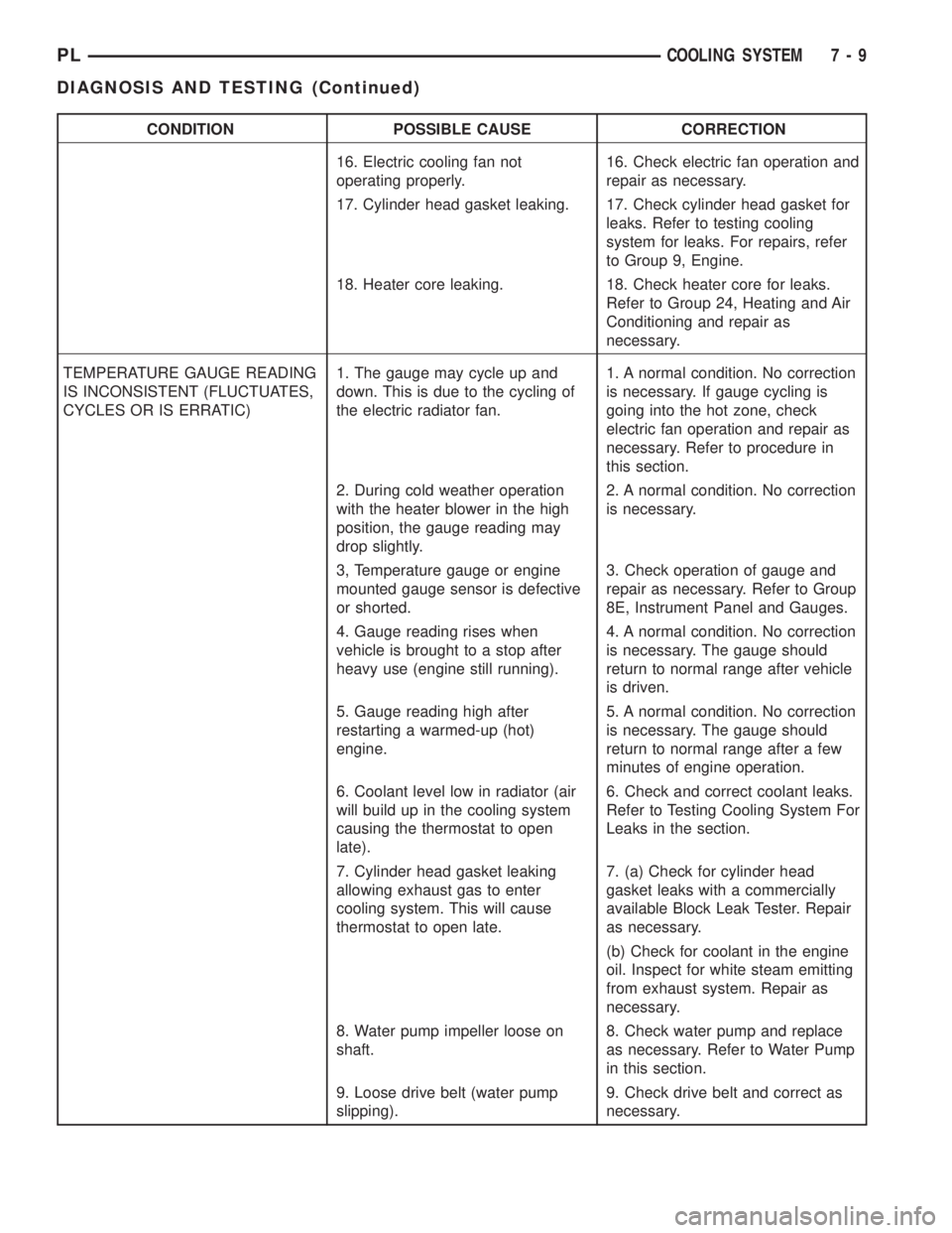
CONDITION POSSIBLE CAUSE CORRECTION
16. Electric cooling fan not
operating properly.16. Check electric fan operation and
repair as necessary.
17. Cylinder head gasket leaking. 17. Check cylinder head gasket for
leaks. Refer to testing cooling
system for leaks. For repairs, refer
to Group 9, Engine.
18. Heater core leaking. 18. Check heater core for leaks.
Refer to Group 24, Heating and Air
Conditioning and repair as
necessary.
TEMPERATURE GAUGE READING
IS INCONSISTENT (FLUCTUATES,
CYCLES OR IS ERRATIC)1. The gauge may cycle up and
down. This is due to the cycling of
the electric radiator fan.1. A normal condition. No correction
is necessary. If gauge cycling is
going into the hot zone, check
electric fan operation and repair as
necessary. Refer to procedure in
this section.
2. During cold weather operation
with the heater blower in the high
position, the gauge reading may
drop slightly.2. A normal condition. No correction
is necessary.
3, Temperature gauge or engine
mounted gauge sensor is defective
or shorted.3. Check operation of gauge and
repair as necessary. Refer to Group
8E, Instrument Panel and Gauges.
4. Gauge reading rises when
vehicle is brought to a stop after
heavy use (engine still running).4. A normal condition. No correction
is necessary. The gauge should
return to normal range after vehicle
is driven.
5. Gauge reading high after
restarting a warmed-up (hot)
engine.5. A normal condition. No correction
is necessary. The gauge should
return to normal range after a few
minutes of engine operation.
6. Coolant level low in radiator (air
will build up in the cooling system
causing the thermostat to open
late).6. Check and correct coolant leaks.
Refer to Testing Cooling System For
Leaks in the section.
7. Cylinder head gasket leaking
allowing exhaust gas to enter
cooling system. This will cause
thermostat to open late.7. (a) Check for cylinder head
gasket leaks with a commercially
available Block Leak Tester. Repair
as necessary.
(b) Check for coolant in the engine
oil. Inspect for white steam emitting
from exhaust system. Repair as
necessary.
8. Water pump impeller loose on
shaft.8. Check water pump and replace
as necessary. Refer to Water Pump
in this section.
9. Loose drive belt (water pump
slipping).9. Check drive belt and correct as
necessary.
PLCOOLING SYSTEM 7 - 9
DIAGNOSIS AND TESTING (Continued)
Page 196 of 1285
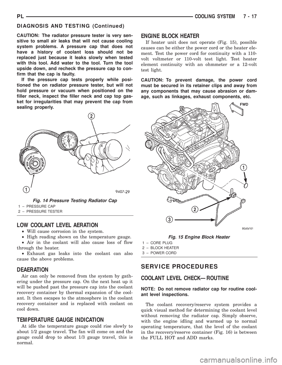
CAUTION: The radiator pressure tester is very sen-
sitive to small air leaks that will not cause cooling
system problems. A pressure cap that does not
have a history of coolant loss should not be
replaced just because it leaks slowly when tested
with this tool. Add water to the tool. Turn the tool
upside down, and recheck the pressure cap to con-
firm that the cap is faulty.
If the pressure cap tests properly while posi-
tioned the on radiator pressure tester, but will not
hold pressure or vacuum when positioned on the
filler neck, inspect the filler neck and cap top gas-
ket for irregularities that may prevent the cap from
sealing properly.
LOW COOLANT LEVEL AERATION
²Will cause corrosion in the system.
²High reading shown on the temperature gauge.
²Air in the coolant will also cause loss of flow
through the heater.
²Exhaust gas leaks into the coolant can also
cause the above problems.
DEAERATION
Air can only be removed from the system by gath-
ering under the pressure cap. On the next heat up it
will be pushed past the pressure cap into the coolant
recovery container by thermal expansion of the cool-
ant. It then escapes to the atmosphere in the coolant
recovery container and is replaced with coolant on
cool down.
TEMPERATURE GAUGE INDICATION
At idle the temperature gauge could rise slowly to
about 1/2 gauge travel. The fan will come on and the
gauge could drop to about 1/3 gauge travel, this is
normal.
ENGINE BLOCK HEATER
If heater unit does not operate (Fig. 15), possible
causes can be either the power cord or the heater ele-
ment. Test the power cord for continuity with a 110-
volt voltmeter or 110-volt test light. Test heater
element continuity with an ohmmeter or a 12-volt
test light.
CAUTION: To prevent damage, the power cord
must be secured in its retainer clips and away from
any components that may cause abrasion or dam-
age, such as linkages, exhaust components, etc.
SERVICE PROCEDURES
COOLANT LEVEL CHECKÐROUTINE
NOTE: Do not remove radiator cap for routine cool-
ant level inspections.
The coolant recovery/reserve system provides a
quick visual method for determining the coolant level
without removing the radiator cap. Simply observe,
with the engine idling and warmed up to normal
operating temperature, that the level of the coolant
in the recovery/reserve container (Fig. 16) is between
the FULL HOT and ADD marks.
Fig. 14 Pressure Testing Radiator Cap
1 ± PRESSURE CAP
2 ± PRESSURE TESTER
Fig. 15 Engine Block Heater
1 ± CORE PLUG
2 ± BLOCK HEATER
3 ± POWER CORD
PLCOOLING SYSTEM 7 - 17
DIAGNOSIS AND TESTING (Continued)
Page 237 of 1285

Loose cable connections will corrode, increase resis-
tance and permit water to enter the coil towers.
These conditions can cause ignition malfunction.
Plastic clips in various locations protect the cables
from damage. When the cables are replaced the clips
must be used to prevent damage to the cables, and
should be rotated about 30É below the horizontal.
ELECTRONIC IGNITION COILS
DESCRIPTION
The coil pack consists of 2 coils molded together.
The coil pack is mounted on the valve cover (Fig. 2).
OPERATION
WARNING: THE DIRECT IGNITION SYSTEM GEN-
ERATES APPROXIMATELY 40,000 VOLTS. PER-
SONAL INJURY COULD RESULT FROM CONTACT
WITH THIS SYSTEM.
High tension leads route to each cylinder from the
coil. The coil fires two spark plugs every power
stroke. One plug is the cylinder under compression,
the other cylinder fires on the exhaust stroke. Coil
number one fires cylinders 1 and 4. Coil number two
fires cylinders 2 and 3. The PCM determines which
of the coils to charge and fire at the correct time.
The Auto Shutdown (ASD) relay provides battery
voltage to the ignition coil. The PCM provides a
ground contact (circuit) for energizing the coil. When
the PCM breaks the contact, the energy in the coil
primary transfers to the secondary causing thespark. The PCM will de-energize the ASD relay if it
does not receive the crankshaft position sensor and
camshaft position sensor inputs. Refer to Auto Shut-
down (ASD) RelayÐPCM Output, in this section for
relay operation.
AUTOMATIC SHUTDOWN RELAY
DESCRIPTION
The ASD relay is located in the PDC (Fig. 3). The
inside top of the PDC cover has label showing relay
and fuse identification.
Fig. 1 Checking Spark Plug Electrode Gap
1 ± TAPER GAUGE
Fig. 2 Ignition Coil Pack
1 ± IGNITION COILS
2 ± SPARK PLUG CABLE
3 ± SPARK PLUG INSULATOR
Fig. 3 Power Distribution Center (PDC)
8D - 2 IGNITION SYSTEMPL
DESCRIPTION AND OPERATION (Continued)