2000 DODGE NEON ccv hose
[x] Cancel search: ccv hosePage 733 of 1285
make sure the dye is thoroughly mixed as indicated
with a bright yellow color under a black light.
(3) Using a black light, inspect the entire engine
for fluorescent dye, particularly at the suspected area
of oil leak. If the oil leak is found and identified,
repair per service manual instructions.
(4) If dye is not observed, drive the vehicle at var-
ious speeds for approximately 24 km (15 miles), and
repeat inspection.
(5)If the oil leak source is not positively
identified at this time, proceed with the air leak
detection test method as follows:
²Disconnect the fresh air hose (makeup air) at
the cylinder head cover and plug or cap the nipple on
the cover.
²Remove the PCV valve hose from the cylinder
head cover. Cap or plug the PCV valve nipple on the
cover.
²Attach an air hose with pressure gauge and reg-
ulator to the dipstick tube.
CAUTION: Do not subject the engine assembly to
more than 20.6 kpa (3 PSI) of test pressure.
²Gradually apply air pressure from 1 psi to 2.5
psi maximum while applying soapy water at the sus-
pected source. Adjust the regulator to the suitable
test pressure that provides the best bubbles which
will pinpoint the leak source. If the oil leak is
detected and identified, repair per service manual
procedures.
²If the leakage occurs at the crankshaft rear oil
seal area, refer to the section, Inspection for Rear
Seal Area Leak.
(6) If no leaks are detected, turn off the air supply.
Remove the air hose, all plugs, and caps. Install the
PCV valve and CCV hose. Proceed to next step.
(7) Clean the oil off the suspect oil leak area using
a suitable solvent. Drive the vehicle at various
speeds approximately 24 km (15 miles). Inspect the
engine for signs of an oil leak by using a black light.
INSPECTION FOR REAR SEAL AREA LEAKS
Since it is sometimes difficult to determine the
source of an oil leak in the rear seal area of theengine, a more involved inspection is necessary. The
following steps should be followed to help pinpoint
the source of the leak.
If the leakage occurs at the crankshaft rear oil seal
area:
(1) Disconnect the battery.
(2) Raise the vehicle.
(3) Remove torque converter or clutch housing
cover and inspect rear of block for evidence of oil.
Use a black light to check for the oil leak. If a leak is
present in this area remove transmission for further
inspection.
(a) Circular spray pattern generally indicates
seal leakage or crankshaft damage.
(b) Where leakage tends to run straight down,
possible causes are a porous block, oil galley cup
plug, bedplate to cylinder block mating surfaces
and seal bore. See proper repair procedures for
these items.
(4) If no leaks are detected, pressurized the crank-
case as previously described.
CAUTION: Do not exceed 20.6 kPa (3 psi).
(5) If the leak is not detected, very slowly turn the
crankshaft and watch for leakage. If a leak is
detected between the crankshaft and seal while
slowly turning the crankshaft, it is possible the
crankshaft seal surface is damaged. The seal area on
the crankshaft could have minor nicks or scratches
that can be polished out with emery cloth.
CAUTION: Use extreme caution when crankshaft
polishing is necessary to remove minor nicks and
scratches. The crankshaft seal flange is especially
machined to complement the function of the rear oil
seal.
(6) For bubbles that remain steady with shaft
rotation, no further inspection can be done until dis-
assembled.
(7) After the oil leak root cause and appropriate
corrective action have been identified, refer to Crank-
shaft Oil SealÐRear for proper replacement proce-
dures.
9 - 10 ENGINEPL
DIAGNOSIS AND TESTING (Continued)
Page 753 of 1285
CAUTION: When using the ASD Fuel System Test,
the Auto Shutdown (ASD) relay will remain ener-
gized for 7 minutes or until the ignition switch is
turned to the OFF position, or Stop All Test is
selected.
EXHAUST MANIFOLD
REMOVAL
(1) Disconnect negative cable from battery.
(2) Raise vehicle on hoist.
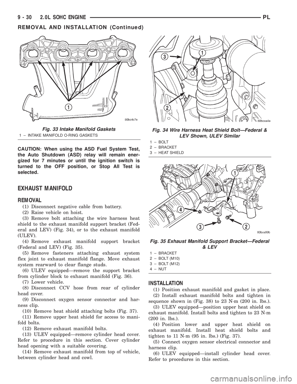
(3) Remove bolt attaching the wire harness heat
shield to the exhaust manifold support bracket (Fed-
eral and LEV) (Fig. 34), or to the exhaust manifold
(ULEV).
(4) Remove exhaust manifold support bracket
(Federal and LEV) (Fig. 35).
(5) Remove fasteners attaching exhaust system
flex joint to exhaust manifold flange. Move exhaust
system rearward to clear flange studs.
(6) ULEV equippedÐremove the support bracket
from cylinder block to exhaust manifold (Fig. 36).
(7) Lower vehicle.
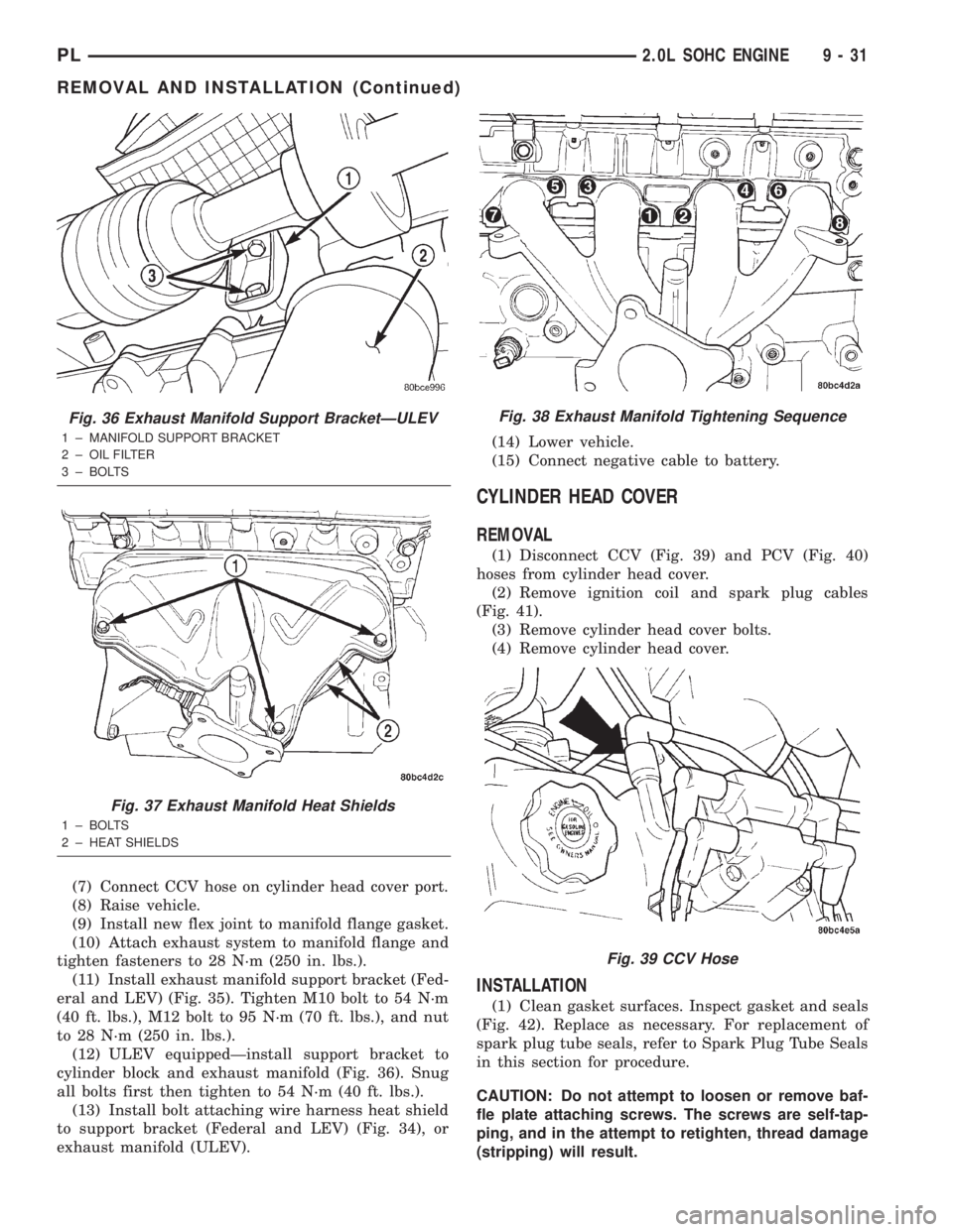
(8) Disconnect CCV hose from rear of cylinder
head cover.
(9) Disconnect oxygen sensor connector and har-
ness clip.
(10) Remove heat shield attaching bolts (Fig. 37).
(11) Remove upper heat shield for access to mani-
fold bolts.
(12) Remove exhaust manifold bolts.
(13) ULEV equippedÐremove cylinder head cover.
Refer to procedure in this section. Cover cylinder
head opening with a suitable covering.
(14) Remove exhaust manifold from top of vehicle,
between cylinder head and cowl.
INSTALLATION
(1) Position exhaust manifold and gasket in place.
(2) Install exhaust manifold bolts and tighten in
sequence shown in (Fig. 38) to 23 N´m (200 in. lbs.).
(3) ULEV equippedÐposition upper heat shield on
exhaust manifold. Install bolts and tighten to 23 N´m
(200 in. lbs.).
(4) Position lower and upper heat shield on
exhaust manifold. Install heat shield bolts and
tighten to 11 N´m (95 in. lbs.) (Fig. 37).
(5) Connect oxygen sensor electrical connector and
harness clip.
(6) ULEV equippedÐinstall cylinder head cover.
Refer to procedures in this section.
Fig. 33 Intake Manifold Gaskets
1 ± INTAKE MANIFOLD O-RING GASKETS
Fig. 34 Wire Harness Heat Shield BoltÐFederal &
LEV Shown, ULEV Similar
1 ± BOLT
2 ± BRACKET
3 ± HEAT SHIELD
Fig. 35 Exhaust Manifold Support BracketÐFederal
& LEV
1 ± BRACKET
2 ± BOLT (M10)
3 ± BOLT (M12)
4 ± NUT
9 - 30 2.0L SOHC ENGINEPL
REMOVAL AND INSTALLATION (Continued)
Page 754 of 1285
(7) Connect CCV hose on cylinder head cover port.
(8) Raise vehicle.
(9) Install new flex joint to manifold flange gasket.
(10) Attach exhaust system to manifold flange and
tighten fasteners to 28 N´m (250 in. lbs.).
(11) Install exhaust manifold support bracket (Fed-
eral and LEV) (Fig. 35). Tighten M10 bolt to 54 N´m
(40 ft. lbs.), M12 bolt to 95 N´m (70 ft. lbs.), and nut
to 28 N´m (250 in. lbs.).
(12) ULEV equippedÐinstall support bracket to
cylinder block and exhaust manifold (Fig. 36). Snug
all bolts first then tighten to 54 N´m (40 ft. lbs.).
(13) Install bolt attaching wire harness heat shield
to support bracket (Federal and LEV) (Fig. 34), or
exhaust manifold (ULEV).(14) Lower vehicle.
(15) Connect negative cable to battery.
CYLINDER HEAD COVER
REMOVAL
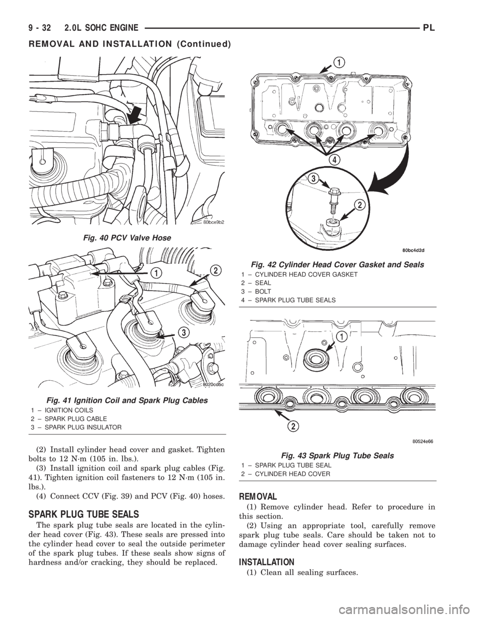
(1) Disconnect CCV (Fig. 39) and PCV (Fig. 40)
hoses from cylinder head cover.
(2) Remove ignition coil and spark plug cables
(Fig. 41).
(3) Remove cylinder head cover bolts.
(4) Remove cylinder head cover.
INSTALLATION
(1) Clean gasket surfaces. Inspect gasket and seals
(Fig. 42). Replace as necessary. For replacement of
spark plug tube seals, refer to Spark Plug Tube Seals
in this section for procedure.
CAUTION: Do not attempt to loosen or remove baf-
fle plate attaching screws. The screws are self-tap-
ping, and in the attempt to retighten, thread damage
(stripping) will result.
Fig. 36 Exhaust Manifold Support BracketÐULEV
1 ± MANIFOLD SUPPORT BRACKET
2 ± OIL FILTER
3 ± BOLTS
Fig. 37 Exhaust Manifold Heat Shields
1 ± BOLTS
2 ± HEAT SHIELDS
Fig. 38 Exhaust Manifold Tightening Sequence
Fig. 39 CCV Hose
PL2.0L SOHC ENGINE 9 - 31
REMOVAL AND INSTALLATION (Continued)
Page 755 of 1285
(2) Install cylinder head cover and gasket. Tighten
bolts to 12 N´m (105 in. lbs.).
(3) Install ignition coil and spark plug cables (Fig.
41). Tighten ignition coil fasteners to 12 N´m (105 in.
lbs.).
(4) Connect CCV (Fig. 39) and PCV (Fig. 40) hoses.
SPARK PLUG TUBE SEALS
The spark plug tube seals are located in the cylin-
der head cover (Fig. 43). These seals are pressed into
the cylinder head cover to seal the outside perimeter
of the spark plug tubes. If these seals show signs of
hardness and/or cracking, they should be replaced.
REMOVAL
(1) Remove cylinder head. Refer to procedure in
this section.
(2) Using an appropriate tool, carefully remove
spark plug tube seals. Care should be taken not to
damage cylinder head cover sealing surfaces.
INSTALLATION
(1) Clean all sealing surfaces.
Fig. 40 PCV Valve Hose
Fig. 41 Ignition Coil and Spark Plug Cables
1 ± IGNITION COILS
2 ± SPARK PLUG CABLE
3 ± SPARK PLUG INSULATOR
Fig. 42 Cylinder Head Cover Gasket and Seals
1 ± CYLINDER HEAD COVER GASKET
2 ± SEAL
3 ± BOLT
4 ± SPARK PLUG TUBE SEALS
Fig. 43 Spark Plug Tube Seals
1 ± SPARK PLUG TUBE SEAL
2 ± CYLINDER HEAD COVER
9 - 32 2.0L SOHC ENGINEPL
REMOVAL AND INSTALLATION (Continued)
Page 760 of 1285
CYLINDER HEAD
REMOVAL
(1) Perform fuel system pressure release procedure
before attempting any repairs.Refer to Group 14,
Fuel System
(2) Disconnect negative battery cable.
(3) Remove power steering/air conditioning drive
belt. Refer to Group 7, Cooling System Accessory
Drive for procedure.
(4) Raise vehicle.
(5) Drain cooling system. Refer to Group 7, Cooling
System.
(6) Remove exhaust pipe from manifold.
(7) Remove right front wheel.
(8) Remove right side splash shield.
(9) Remove generator belt. Refer to Group 7, Cool-
ing System Accessory Drive Belts for procedure.
(10) Remove crankshaft damper. Refer to proce-
dure in this section.
(11) Remove lower torque strut.
(12) Lower vehicle and remove upper torque strut.
(13) Remove ground strap and power steering hose
support clip from engine mount bracket.
(14) Remove power steering pump assembly and
set aside.
(15) Support engine from beneath with a suitable
jack.
(16) Remove right side engine mount to bracket
through bolt.
(17) Remove the lower engine mount bracket bolt.
Raise engine slightly and remove the upper engine
mount bracket bolts.(18) Remove engine mount bracket. This procedure
may require additional raising/lowering of engine
until bracket will clear engine components.
(19) Remove front timing belt cover.
(20) Rotate engine until timing marks are aligned.
(21) Remove timing belt and tensioner. Refer to
procedures in this section.
(22) Remove camshaft sprocket. Refer to proce-
dures in this section.
(23) Remove rear timing belt cover.
(24) Disconnect fuel line at fuel rail.
(25) Remove coolant recovery container.
(26) Remove ground wire to cylinder head.
(27) Remove upper radiator hose.
(28) Remove intake manifold. Refer to procedure
in this section.
(29) Disconnect ignition coil electrical connector.
Remove coil pack and spark plug cables from engine.
(30) Remove Crankcase Closed Ventilation (CCV)
hose from cylinder head cover.
(31) Disconnect cam sensor and coolant tempera-
ture electrical connectors.
(32) Remove heater tube to cylinder head attach-
ing fasteners.
(33) Remove heater hose from thermostat housing
connector.
(34) Remove cylinder head cover.
(35) Remove cylinder head bolts.
(36) Remove cylinder head and gasket (Fig. 55).
PL2.0L SOHC ENGINE 9 - 37
REMOVAL AND INSTALLATION (Continued)
Page 762 of 1285
(2) Apply MopartGasket Sealant (aerosol can) to
both sides of the new cylinder head gasket.
(3) Position a new cylinder head gasket on the
locating dowels.
(4) Position crankshaft sprocket to TDC, then
rotate crankshaft until mark is three teeth before
TDC (Fig. 59). This will ensure that no piston-to-
valve contact occurs upon installation of cylinder
head in the event of camshaft rotation.
(5) Position the cylinder head onto the cylinder
block. Make sure the cylinder head seats fully over
the locating dowels.
(6) Before installing cylinder head bolts, the
threads should be oiled with engine oil. The 4 shorter
bolts 164 mm (6.45 in.), are to be installed in posi-
tions 7, 8, 9, and 10 (Fig. 60).
(7) Tighten the cylinder head bolts in the sequence
shown in (Fig. 60). Using the 4 step torque method,
tighten according to the following values:²First All to 34 N´m (25 ft. lbs.)
²Second All to 68 N´m (50 ft. lbs.)
²Third All to 68 N´m (50 ft. lbs.)
²Fourth Turn an additional 1/4 Turn.Do not use
a torque wrench for this step.
(8) Install cylinder head cover.
(9) Install heater hose to thermostat housing con-
nector.
(10) Install heater tube to cylinder head attaching
fasteners.
(11) Connect cam sensor and coolant temperature
electrical connectors.
(12) Connect Crankcase Closed Ventilation (CCV)
hose to cylinder head cover.
Fig. 56 Checking Cylinder Head Flatness
1 ± FEELER GAUGE
2 ± STRAIGHT EDGE
Fig. 57 Checking Bolts for Stretching (Necking)
1 ± STRETCHED BOLT
2 ± THREADS ARE NOT STRAIGHT ON LINE
3 ± THREADS ARE STRAIGHT ON LINE
4 ± UNSTRETCHED BOLT
Fig. 58 Proper Tool Usage for Surface Preparation
1 ± ABRASIVE PAD
2 ± 3M ROLOCYBRISTLE DISC
3 ± PLASTIC/WOOD SCRAPER
Fig. 59 Crankshaft Sprocket Position
1 ± TDC MARK
PL2.0L SOHC ENGINE 9 - 39
REMOVAL AND INSTALLATION (Continued)