2000 DODGE NEON gasket
[x] Cancel search: gasketPage 115 of 1285
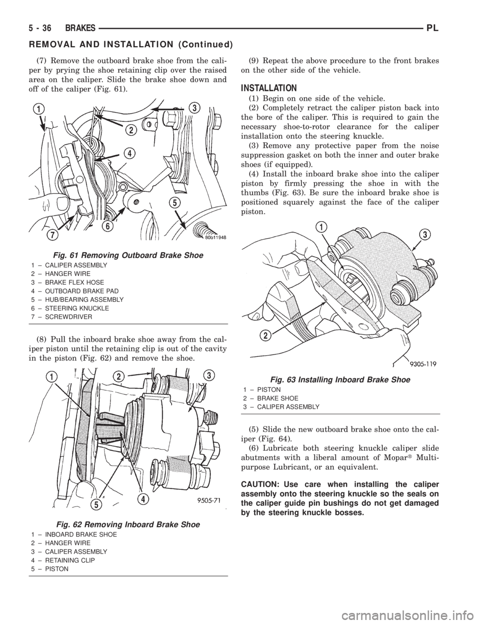
(7) Remove the outboard brake shoe from the cali-
per by prying the shoe retaining clip over the raised
area on the caliper. Slide the brake shoe down and
off of the caliper (Fig. 61).
(8) Pull the inboard brake shoe away from the cal-
iper piston until the retaining clip is out of the cavity
in the piston (Fig. 62) and remove the shoe.(9) Repeat the above procedure to the front brakes
on the other side of the vehicle.
INSTALLATION
(1) Begin on one side of the vehicle.
(2) Completely retract the caliper piston back into
the bore of the caliper. This is required to gain the
necessary shoe-to-rotor clearance for the caliper
installation onto the steering knuckle.
(3) Remove any protective paper from the noise
suppression gasket on both the inner and outer brake
shoes (if equipped).
(4) Install the inboard brake shoe into the caliper
piston by firmly pressing the shoe in with the
thumbs (Fig. 63). Be sure the inboard brake shoe is
positioned squarely against the face of the caliper
piston.
(5) Slide the new outboard brake shoe onto the cal-
iper (Fig. 64).
(6) Lubricate both steering knuckle caliper slide
abutments with a liberal amount of MopartMulti-
purpose Lubricant, or an equivalent.
CAUTION: Use care when installing the caliper
assembly onto the steering knuckle so the seals on
the caliper guide pin bushings do not get damaged
by the steering knuckle bosses.
Fig. 61 Removing Outboard Brake Shoe
1 ± CALIPER ASSEMBLY
2 ± HANGER WIRE
3 ± BRAKE FLEX HOSE
4 ± OUTBOARD BRAKE PAD
5 ± HUB/BEARING ASSEMBLY
6 ± STEERING KNUCKLE
7 ± SCREWDRIVER
Fig. 62 Removing Inboard Brake Shoe
1 ± INBOARD BRAKE SHOE
2 ± HANGER WIRE
3 ± CALIPER ASSEMBLY
4 ± RETAINING CLIP
5 ± PISTON
Fig. 63 Installing Inboard Brake Shoe
1 ± PISTON
2 ± BRAKE SHOE
3 ± CALIPER ASSEMBLY
5 - 36 BRAKESPL
REMOVAL AND INSTALLATION (Continued)
Page 119 of 1285
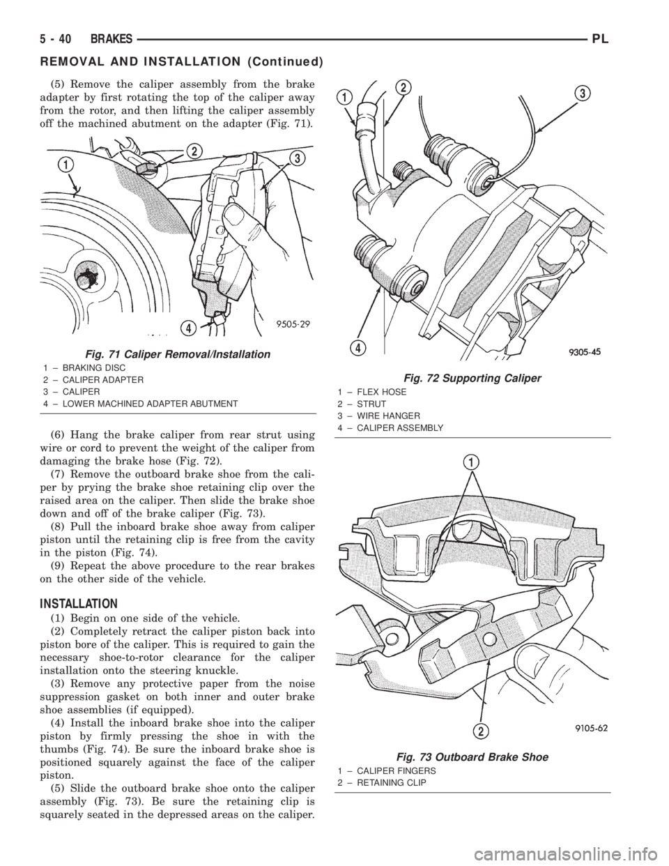
(5) Remove the caliper assembly from the brake
adapter by first rotating the top of the caliper away
from the rotor, and then lifting the caliper assembly
off the machined abutment on the adapter (Fig. 71).
(6) Hang the brake caliper from rear strut using
wire or cord to prevent the weight of the caliper from
damaging the brake hose (Fig. 72).
(7) Remove the outboard brake shoe from the cali-
per by prying the brake shoe retaining clip over the
raised area on the caliper. Then slide the brake shoe
down and off of the brake caliper (Fig. 73).
(8) Pull the inboard brake shoe away from caliper
piston until the retaining clip is free from the cavity
in the piston (Fig. 74).
(9) Repeat the above procedure to the rear brakes
on the other side of the vehicle.
INSTALLATION
(1) Begin on one side of the vehicle.
(2) Completely retract the caliper piston back into
piston bore of the caliper. This is required to gain the
necessary shoe-to-rotor clearance for the caliper
installation onto the steering knuckle.
(3) Remove any protective paper from the noise
suppression gasket on both inner and outer brake
shoe assemblies (if equipped).
(4) Install the inboard brake shoe into the caliper
piston by firmly pressing the shoe in with the
thumbs (Fig. 74). Be sure the inboard brake shoe is
positioned squarely against the face of the caliper
piston.
(5) Slide the outboard brake shoe onto the caliper
assembly (Fig. 73). Be sure the retaining clip is
squarely seated in the depressed areas on the caliper.
Fig. 71 Caliper Removal/Installation
1 ± BRAKING DISC
2 ± CALIPER ADAPTER
3 ± CALIPER
4 ± LOWER MACHINED ADAPTER ABUTMENT
Fig. 72 Supporting Caliper
1 ± FLEX HOSE
2 ± STRUT
3 ± WIRE HANGER
4 ± CALIPER ASSEMBLY
Fig. 73 Outboard Brake Shoe
1 ± CALIPER FINGERS
2 ± RETAINING CLIP
5 - 40 BRAKESPL
REMOVAL AND INSTALLATION (Continued)
Page 126 of 1285
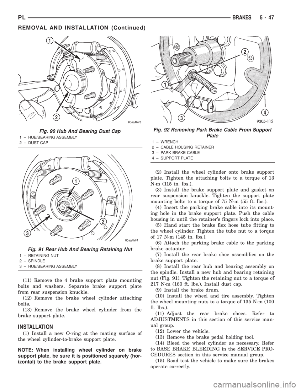
(11) Remove the 4 brake support plate mounting
bolts and washers. Separate brake support plate
from rear suspension knuckle.
(12) Remove the brake wheel cylinder attaching
bolts.
(13) Remove the brake wheel cylinder from the
brake support plate.
INSTALLATION
(1) Install a new O-ring at the mating surface of
the wheel cylinder-to-brake support plate.
NOTE: When installing wheel cylinder on brake
support plate, be sure it is positioned squarely (hor-
izontal) to the brake support plate.(2) Install the wheel cylinder onto brake support
plate. Tighten the attaching bolts to a torque of 13
N´m (115 in. lbs.).
(3) Install the brake support plate and gasket on
rear suspension knuckle. Tighten the support plate
mounting bolts to a torque of 75 N´m (55 ft. lbs.).
(4) Insert the parking brake cable into its mount-
ing hole in the brake support plate. Push the cable
housing in until the retainer's fingers lock into place.
(5) Hand start the brake flex hose tube fitting to
the wheel cylinder. Tighten the tube nut to a torque
of 17 N´m (145 in. lbs.).
(6) Attach the parking brake cable to the parking
brake actuator.
(7) Install the rear brake shoe assemblies on the
brake support plate.
(8) Install the rear hub and bearing assembly on
the spindle. Install a new hub and bearing retaining
nut (Fig. 91). Tighten the retaining nut to a torque of
217 N´m (160 ft. lbs.). Install dust cap.
(9) Install the brake drum.
(10) Install the wheel and tire assembly. Tighten
the wheel mounting nuts to a torque of 135 N´m (100
ft. lbs.).
(11) Adjust the rear brake shoes. Refer to
ADJUSTMENTS in this section of this service man-
ual group.
(12) Lower the vehicle.
(13) Remove the brake pedal holding tool.
(14) Bleed the wheel cylinder as necessary. Refer
to BASE BRAKE BLEEDING in the SERVICE PRO-
CEDURES section in this service manual group.
(15) Road test the vehicle to make sure the brakes
operate correctly.
Fig. 90 Hub And Bearing Dust Cap
1 ± HUB/BEARING ASSEMBLY
2 ± DUST CAP
Fig. 91 Rear Hub And Bearing Retaining Nut
1 ± RETAINING NUT
2 ± SPINDLE
3 ± HUB/BEARING ASSEMBLY
Fig. 92 Removing Park Brake Cable From Support
Plate
1 ± WRENCH
2 ± CABLE HOUSING RETAINER
3 ± PARK BRAKE CABLE
4 ± SUPPORT PLATE
PLBRAKES 5 - 47
REMOVAL AND INSTALLATION (Continued)
Page 183 of 1285
Radiator cooling fan control operation is accomplished
two ways. The fan always runs when the air condition-
ing compressor clutch is engaged. In addition to this
control, the fan is turned on by the temperature of the
coolant which is sensed by the coolant temperature sen-
sor which sends the message to the Powertrain Control
Module (PCM). The PCM turns on the fan through a
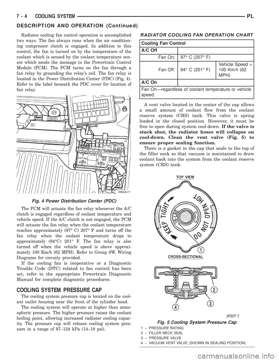
fan relay by grounding the relay's coil. The fan relay is
located in the Power Distribution Center (PDC) (Fig. 4).
Refer to the label beneath the PDC cover for location of
fan relay.
The PCM will actuate the fan relay whenever the A/C
clutch is engaged regardless of coolant temperature and
vehicle speed. If the A/C clutch is not engaged, the PCM
will actuate the fan relay when the coolant temperature
reaches approximately (97É C) 207É F and turns off the
fan relay when the coolant temperature drops to
approximately (94ÉC) 201É F. The fan relay is also
turned off when the vehicle speed is above approxi-
mately 100 Km/h (62 MPH). Refer to Group 8W, Wiring
Diagrams for circuity provided.
If the cooling fan is inoperative or a Diagnostic
Trouble Code (DTC) related to fan control has been
set, refer to the appropriate Powertrain Diagnostic
Manual for complete diagnostic procedures.
COOLING SYSTEM PRESSURE CAP
The cooling system pressure cap is located on the cool-
ant outlet housing near the front of the cylinder head.
The cooling system will operate at higher than atmo-
spheric pressure. The higher pressure raises the coolant
boiling point, allowing increased radiator cooling capac-
ity. The pressure cap will release cooling system pres-
sure in a range of 97±124 kPa (14±18 psi).
A vent valve located in the center of the cap allows
a small amount of coolant flow from the coolant
reserve system (CRS) tank. This valve is spring
loaded in the closed position. However, it must be
free to open during system cool-down.If the valve is
stuck shut, the radiator hoses will collapse on
cool-down. Clean the vent valve (Fig. 5) to
ensure proper sealing function.
There is a gasket in the cap that seals to the top of
the filler neck so that vacuum is maintained to draw
coolant back into the system from the coolant reserve
system (CRS) tank.
Fig. 4 Power Distribution Center (PDC)
RADIATOR COOLING FAN OPERATION CHART
Cooling Fan Control
A/C Off
Fan On: 97É C (207É F)
Fan Off: 94É C (201É F)Vehicle Speed >
100 Km/h (62
MPH)
A/C On
Fan OnÐregardless of coolant temperature or vehicle
speed.
Fig. 5 Cooling System Pressure Cap
1 ± PRESSURE RATING
2 ± FILLER NECK SEAL
3 ± PRESSURE VALVE
4 ± VACUUM VENT VALVE (SHOWN IN SEALING POSITION)
7 - 4 COOLING SYSTEMPL
DESCRIPTION AND OPERATION (Continued)
Page 188 of 1285
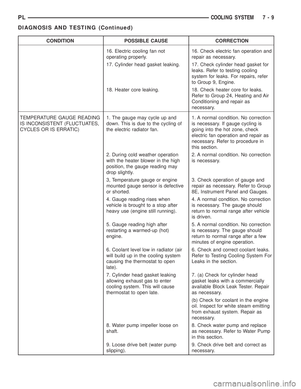
CONDITION POSSIBLE CAUSE CORRECTION
16. Electric cooling fan not
operating properly.16. Check electric fan operation and
repair as necessary.
17. Cylinder head gasket leaking. 17. Check cylinder head gasket for
leaks. Refer to testing cooling
system for leaks. For repairs, refer
to Group 9, Engine.
18. Heater core leaking. 18. Check heater core for leaks.
Refer to Group 24, Heating and Air
Conditioning and repair as
necessary.
TEMPERATURE GAUGE READING
IS INCONSISTENT (FLUCTUATES,
CYCLES OR IS ERRATIC)1. The gauge may cycle up and
down. This is due to the cycling of
the electric radiator fan.1. A normal condition. No correction
is necessary. If gauge cycling is
going into the hot zone, check
electric fan operation and repair as
necessary. Refer to procedure in
this section.
2. During cold weather operation
with the heater blower in the high
position, the gauge reading may
drop slightly.2. A normal condition. No correction
is necessary.
3, Temperature gauge or engine
mounted gauge sensor is defective
or shorted.3. Check operation of gauge and
repair as necessary. Refer to Group
8E, Instrument Panel and Gauges.
4. Gauge reading rises when
vehicle is brought to a stop after
heavy use (engine still running).4. A normal condition. No correction
is necessary. The gauge should
return to normal range after vehicle
is driven.
5. Gauge reading high after
restarting a warmed-up (hot)
engine.5. A normal condition. No correction
is necessary. The gauge should
return to normal range after a few
minutes of engine operation.
6. Coolant level low in radiator (air
will build up in the cooling system
causing the thermostat to open
late).6. Check and correct coolant leaks.
Refer to Testing Cooling System For
Leaks in the section.
7. Cylinder head gasket leaking
allowing exhaust gas to enter
cooling system. This will cause
thermostat to open late.7. (a) Check for cylinder head
gasket leaks with a commercially
available Block Leak Tester. Repair
as necessary.
(b) Check for coolant in the engine
oil. Inspect for white steam emitting
from exhaust system. Repair as
necessary.
8. Water pump impeller loose on
shaft.8. Check water pump and replace
as necessary. Refer to Water Pump
in this section.
9. Loose drive belt (water pump
slipping).9. Check drive belt and correct as
necessary.
PLCOOLING SYSTEM 7 - 9
DIAGNOSIS AND TESTING (Continued)
Page 195 of 1285
the coolant to expand. Reattach the tester. If the nee-
dle on the dial fluctuates it indicates a combustion
leak, usually a head gasket leak.
WARNING: WITH THE PRESSURE TESTER IN
PLACE PRESSURE BUILDS UP QUICKLY. ANY
EXCESSIVE PRESSURE BUILD-UP DUE TO CON-
TINUOUS ENGINE OPERATION MUST BE
RELEASED TO A SAFE PRESSURE POINT. NEVER
PERMIT PRESSURE TO EXCEED 138 kPa (20 psi).
If the needle on the dial does not fluctuate, race
the engine a few times. If an abnormal amount of
coolant or steam is emitted from the tail pipe, it may
indicate a faulty head gasket, cracked engine block,
or cracked cylinder head.
There may be internal leaks, which can be deter-
mined by removing the oil dipstick. If water globules
appear intermixed with the oil, it indicates an inter-
nal leak in the engine. If there is an internal leak,
the engine must be disassembled for repair.
PRESSURE CAP TO FILLER NECK SEAL
PRESSURE RELIEF CHECK
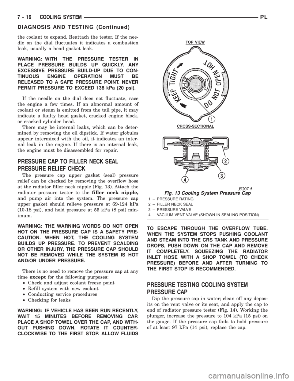
The pressure cap upper gasket (seal) pressure
relief can be checked by removing the overflow hose
at the radiator filler neck nipple (Fig. 13). Attach the
radiator pressure tester to thefiller neck nipple,
and pump air into the system. The pressure cap
upper gasket should relieve pressure at 69-124 kPa
(10-18 psi), and hold pressure at 55 kPa (8 psi) min-
imum.
WARNING: THE WARNING WORDS DO NOT OPEN
HOT ON THE PRESSURE CAP IS A SAFETY PRE-
CAUTION. WHEN HOT, THE COOLING SYSTEM
BUILDS UP PRESSURE. TO PREVENT SCALDING
OR OTHER INJURY, THE PRESSURE CAP SHOULD
NOT BE REMOVED WHILE THE SYSTEM IS HOT
AND/OR UNDER PRESSURE.
There is no need to remove the pressure cap at any
timeexceptfor the following purposes:
²Check and adjust coolant freeze point
²Refill system with new coolant
²Conducting service procedures
²Checking for leaks
WARNING: IF VEHICLE HAS BEEN RUN RECENTLY,
WAIT 15 MINUTES BEFORE REMOVING CAP.
PLACE A SHOP TOWEL OVER THE CAP, AND WITH-
OUT PUSHING DOWN, ROTATE IT COUNTER-
CLOCKWISE TO THE FIRST STOP. ALLOW FLUIDSTO ESCAPE THROUGH THE OVERFLOW TUBE.
WHEN THE SYSTEM STOPS PUSHING COOLANT
AND STEAM INTO THE CRS TANK AND PRESSURE
DROPS, PUSH DOWN ON THE CAP AND REMOVE
IT COMPLETELY. SQUEEZING THE RADIATOR
INLET HOSE WITH A SHOP TOWEL (TO CHECK
PRESSURE) BEFORE AND AFTER TURNING TO
THE FIRST STOP IS RECOMMENDED.
PRESSURE TESTING COOLING SYSTEM
PRESSURE CAP
Dip the pressure cap in water; clean off any depos-
its on the vent valve or its seat, and apply the cap to
end of radiator pressure tester (Fig. 14). Working the
plunger, increase the pressure to 104 kPa (15 psi) on
the gauge. If the pressure cap fails to hold pressure
of at least 97 kPa (14 psi), replace the cap.
Fig. 13 Cooling System Pressure Cap
1 ± PRESSURE RATING
2 ± FILLER NECK SEAL
3 ± PRESSURE VALVE
4 ± VACUUM VENT VALVE (SHOWN IN SEALING POSITION)
7 - 16 COOLING SYSTEMPL
DIAGNOSIS AND TESTING (Continued)
Page 198 of 1285
COOLING SYSTEMÐDRAINING
NOTE: Drain, flush, and fill the cooling system at
the mileage or time intervals specified in Group 0,
Lubrication and Maintenance. If the solution is dirty,
rusty, or contains a considerable amount of sedi-
ment; clean and flush with a reliable cooling system
cleaner. Care should be taken in disposing of the
used engine coolant from your vehicle. Check gov-
ernmental regulations for disposal of used engine
coolant.
Without removing radiator pressure cap and
with system not under pressure:
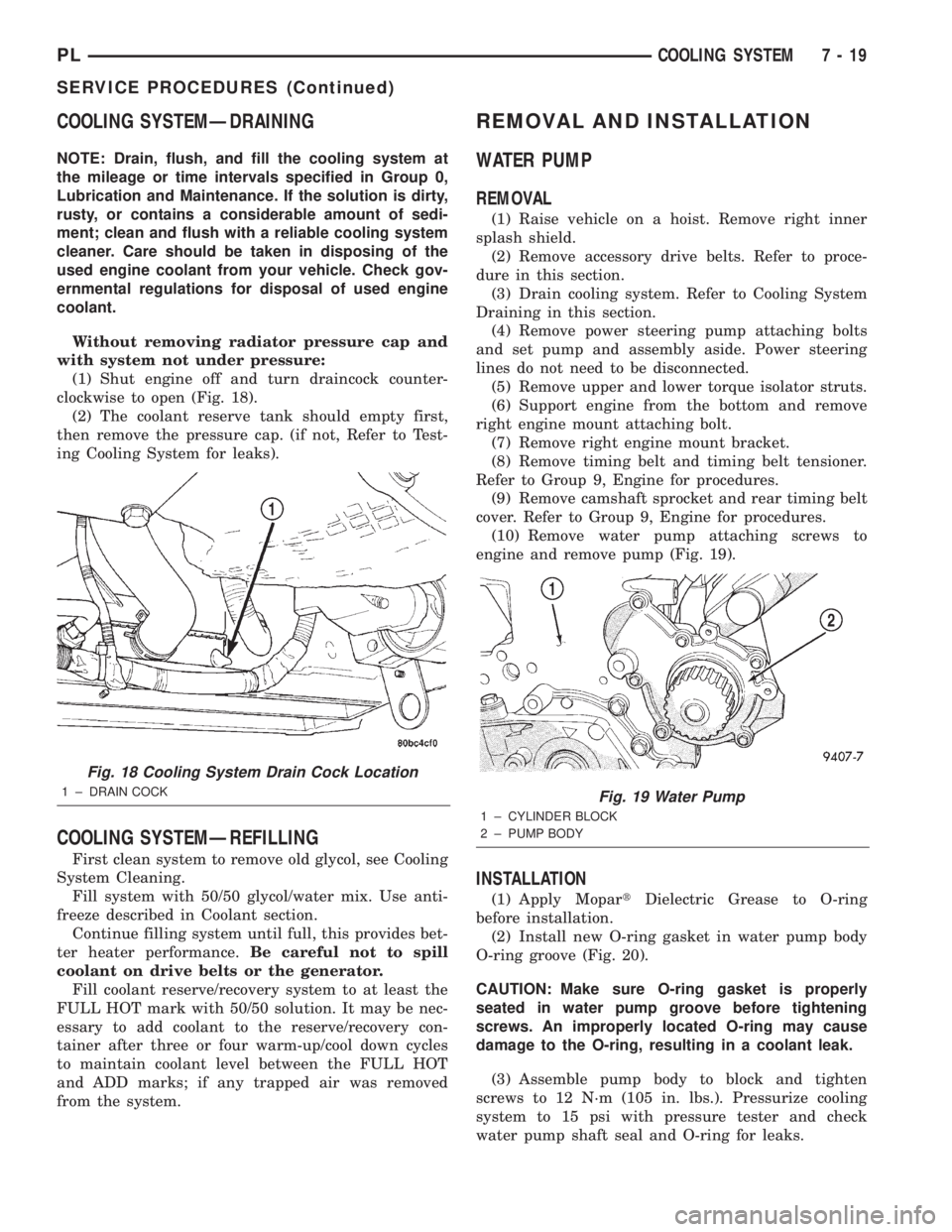
(1) Shut engine off and turn draincock counter-
clockwise to open (Fig. 18).
(2) The coolant reserve tank should empty first,
then remove the pressure cap. (if not, Refer to Test-
ing Cooling System for leaks).
COOLING SYSTEMÐREFILLING
First clean system to remove old glycol, see Cooling
System Cleaning.
Fill system with 50/50 glycol/water mix. Use anti-
freeze described in Coolant section.
Continue filling system until full, this provides bet-
ter heater performance.Be careful not to spill
coolant on drive belts or the generator.
Fill coolant reserve/recovery system to at least the
FULL HOT mark with 50/50 solution. It may be nec-
essary to add coolant to the reserve/recovery con-
tainer after three or four warm-up/cool down cycles
to maintain coolant level between the FULL HOT
and ADD marks; if any trapped air was removed
from the system.
REMOVAL AND INSTALLATION
WATER PUMP
REMOVAL
(1) Raise vehicle on a hoist. Remove right inner
splash shield.
(2) Remove accessory drive belts. Refer to proce-
dure in this section.
(3) Drain cooling system. Refer to Cooling System
Draining in this section.
(4) Remove power steering pump attaching bolts
and set pump and assembly aside. Power steering
lines do not need to be disconnected.
(5) Remove upper and lower torque isolator struts.
(6) Support engine from the bottom and remove
right engine mount attaching bolt.
(7) Remove right engine mount bracket.
(8) Remove timing belt and timing belt tensioner.
Refer to Group 9, Engine for procedures.
(9) Remove camshaft sprocket and rear timing belt
cover. Refer to Group 9, Engine for procedures.
(10) Remove water pump attaching screws to
engine and remove pump (Fig. 19).
INSTALLATION
(1) Apply MopartDielectric Grease to O-ring
before installation.
(2) Install new O-ring gasket in water pump body
O-ring groove (Fig. 20).
CAUTION: Make sure O-ring gasket is properly
seated in water pump groove before tightening
screws. An improperly located O-ring may cause
damage to the O-ring, resulting in a coolant leak.
(3) Assemble pump body to block and tighten
screws to 12 N´m (105 in. lbs.). Pressurize cooling
system to 15 psi with pressure tester and check
water pump shaft seal and O-ring for leaks.
Fig. 18 Cooling System Drain Cock Location
1 ± DRAIN COCKFig. 19 Water Pump
1 ± CYLINDER BLOCK
2 ± PUMP BODY
PLCOOLING SYSTEM 7 - 19
SERVICE PROCEDURES (Continued)
Page 207 of 1285
SHROUD
REMOVAL
(1) Remove cooling fan module. Refer to procedure
in this section.
(2) Remove fan and fan motor as previously
described.
INSTALLATION
(1) Install fan motor and fan as previously
described.
(2) Install cooling fan module. Refer to procedure
in this section.
CLEANING AND INSPECTION
WATER PUMP
Replace water pump body assembly if it has any of
these defects:
(1) Cracks or damage on the body.
(2) Coolant leaks from the shaft seal, evident by
coolant traces on the pump body.
(3) Loose or rough turning bearing.
(4) Impeller rubs either the pump body or the
engine block.
(5) Impeller loose or damaged.
(6) Sprocket or sprocket flange loose or damaged.
ACCESSORY DRIVE BELT INSPECTION
Belt replacement under any or all of the following
conditions is required, excessive wear, frayed cords or
severe glazing.
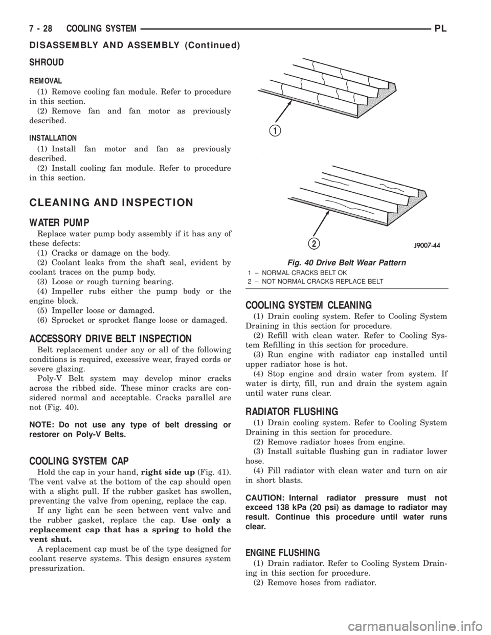
Poly-V Belt system may develop minor cracks
across the ribbed side. These minor cracks are con-
sidered normal and acceptable. Cracks parallel are
not (Fig. 40).
NOTE: Do not use any type of belt dressing or
restorer on Poly-V Belts.
COOLING SYSTEM CAP
Hold the cap in your hand,right side up(Fig. 41).
The vent valve at the bottom of the cap should open
with a slight pull. If the rubber gasket has swollen,
preventing the valve from opening, replace the cap.
If any light can be seen between vent valve and
the rubber gasket, replace the cap.Use only a
replacement cap that has a spring to hold the
vent shut.
A replacement cap must be of the type designed for
coolant reserve systems. This design ensures system
pressurization.
COOLING SYSTEM CLEANING
(1) Drain cooling system. Refer to Cooling System
Draining in this section for procedure.
(2) Refill with clean water. Refer to Cooling Sys-
tem Refilling in this section for procedure.
(3) Run engine with radiator cap installed until
upper radiator hose is hot.
(4) Stop engine and drain water from system. If
water is dirty, fill, run and drain the system again
until water runs clear.
RADIATOR FLUSHING
(1) Drain cooling system. Refer to Cooling System
Draining in this section for procedure.
(2) Remove radiator hoses from engine.
(3) Install suitable flushing gun in radiator lower
hose.
(4) Fill radiator with clean water and turn on air
in short blasts.
CAUTION: Internal radiator pressure must not
exceed 138 kPa (20 psi) as damage to radiator may
result. Continue this procedure until water runs
clear.
ENGINE FLUSHING
(1) Drain radiator. Refer to Cooling System Drain-
ing in this section for procedure.
(2) Remove hoses from radiator.
Fig. 40 Drive Belt Wear Pattern
1 ± NORMAL CRACKS BELT OK
2 ± NOT NORMAL CRACKS REPLACE BELT
7 - 28 COOLING SYSTEMPL
DISASSEMBLY AND ASSEMBLY (Continued)