2000 DODGE NEON washer fluid
[x] Cancel search: washer fluidPage 4 of 1285
MAINTENANCE SCHEDULES
TABLE OF CONTENTS
page page
DESCRIPTION AND OPERATION
MAINTENANCE SCHEDULES................3
SPECIFICATIONS
UNSCHEDULED INSPECTION................3SCHEDULE ± A...........................3
SCHEDULE ± B...........................4
DESCRIPTION AND OPERATION
MAINTENANCE SCHEDULES
There are two maintenance schedules that show
proper service for your vehicle.
First is Schedule ±A. It lists all the scheduled
maintenance to be performed under ªnormalº operat-
ing conditions.
Second is Schedule ±B. It is a schedule for vehi-
cles that are operated under the following conditions:
²Frequent short trip driving less than 5 miles (8
km)
²Frequent driving in dusty conditions
²Extensive idling
²More than 50% of the driving is at sustained
high speeds during hot weather, above 90É F (32É C)
SPECIFICATIONS
UNSCHEDULED INSPECTION
At Each Stop For Fuel
²Check engine oil level and add as required.
²Check windshield washer solvent and add as
required.
Once A Month
²Check tire pressure and look for unusual wear
or damage.
²Inspect the battery and clean and tighten termi-
nals as required.
²Check fluid levels of coolant reservoir, brake
master cylinder, power steering and transmission.
Add fluid as required.
²Check all lights and all other electrical items for
correct operation.
At Each Oil Change
²Inspect the exhaust system.
²Inspect brake hoses.
²Inspect the CV joints and front suspension com-
ponent boots and seals.²Rotate the tires at each oil change interval
shown on Schedule ± A (7,500 miles - 12 000 km) or
every other interval on Schedule ± B (6,000 miles -
10 000 km).
²Check the engine coolant level, hoses, and
clamps.
If mileage is less than 7,500 miles (12 000 km)
yearly, replace the engine oil filter at each oil change.
EMISSION CONTROL SYSTEM MAINTENANCE
The scheduled emission maintenance listed inbold
typeon the Maintenance Schedules, must be done at
the mileage specified to assure the continued proper
functioning of the emission control system. These,
and all other maintenance services included in this
manual, should be done to provide the best vehicle
performance and reliability. More frequent mainte-
nance may be needed for vehicles in severe operating
conditions such as dusty areas and very short trip
driving.
FLUID FILL POINTS AND LUBRICATION
LOCATIONS
The fluid fill/check locations and lubrication loca-
tions are located in each applicable group.
SCHEDULE ± A
7,500 Miles (12 000 km) or at 6 months
²Change the engine oil.
²Replace the engine oil filter.
15,000 Miles (24 000 km) or at 12 months
²Change the engine oil.
²Replace the engine oil filter.
²Adjust the drive belt tension.
22,500 Miles (36 000 km) or at 18 months
²Change the engine oil.
²Replace the engine oil filter.
²Inspect the front brake pads and rear brake lin-
ings.
PLLUBRICATION AND MAINTENANCE 0 - 3
Page 49 of 1285
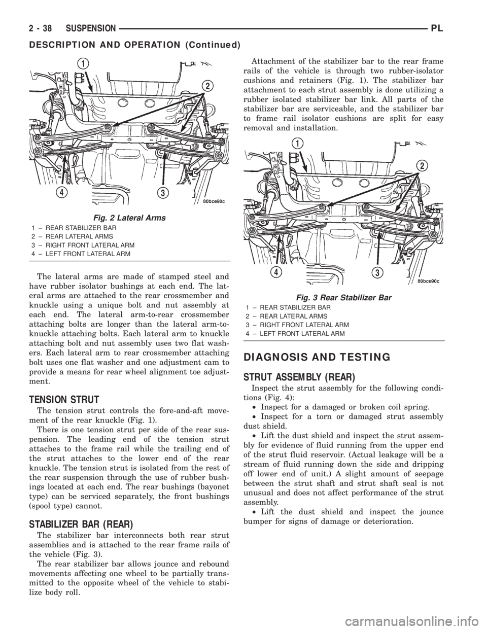
The lateral arms are made of stamped steel and
have rubber isolator bushings at each end. The lat-
eral arms are attached to the rear crossmember and
knuckle using a unique bolt and nut assembly at
each end. The lateral arm-to-rear crossmember
attaching bolts are longer than the lateral arm-to-
knuckle attaching bolts. Each lateral arm to knuckle
attaching bolt and nut assembly uses two flat wash-
ers. Each lateral arm to rear crossmember attaching
bolt uses one flat washer and one adjustment cam to
provide a means for rear wheel alignment toe adjust-
ment.
TENSION STRUT
The tension strut controls the fore-and-aft move-
ment of the rear knuckle (Fig. 1).
There is one tension strut per side of the rear sus-
pension. The leading end of the tension strut
attaches to the frame rail while the trailing end of
the strut attaches to the lower end of the rear
knuckle. The tension strut is isolated from the rest of
the rear suspension through the use of rubber bush-
ings located at each end. The rear bushings (bayonet
type) can be serviced separately, the front bushings
(spool type) cannot.
STABILIZER BAR (REAR)
The stabilizer bar interconnects both rear strut
assemblies and is attached to the rear frame rails of
the vehicle (Fig. 3).
The rear stabilizer bar allows jounce and rebound
movements affecting one wheel to be partially trans-
mitted to the opposite wheel of the vehicle to stabi-
lize body roll.Attachment of the stabilizer bar to the rear frame
rails of the vehicle is through two rubber-isolator
cushions and retainers (Fig. 1). The stabilizer bar
attachment to each strut assembly is done utilizing a
rubber isolated stabilizer bar link. All parts of the
stabilizer bar are serviceable, and the stabilizer bar
to frame rail isolator cushions are split for easy
removal and installation.
DIAGNOSIS AND TESTING
STRUT ASSEMBLY (REAR)
Inspect the strut assembly for the following condi-
tions (Fig. 4):
²Inspect for a damaged or broken coil spring.
²Inspect for a torn or damaged strut assembly
dust shield.
²Lift the dust shield and inspect the strut assem-
bly for evidence of fluid running from the upper end
of the strut fluid reservoir. (Actual leakage will be a
stream of fluid running down the side and dripping
off lower end of unit.) A slight amount of seepage
between the strut shaft and strut shaft seal is not
unusual and does not affect performance of the strut
assembly.
²Lift the dust shield and inspect the jounce
bumper for signs of damage or deterioration.
Fig. 2 Lateral Arms
1 ± REAR STABILIZER BAR
2 ± REAR LATERAL ARMS
3 ± RIGHT FRONT LATERAL ARM
4 ± LEFT FRONT LATERAL ARM
Fig. 3 Rear Stabilizer Bar
1 ± REAR STABILIZER BAR
2 ± REAR LATERAL ARMS
3 ± RIGHT FRONT LATERAL ARM
4 ± LEFT FRONT LATERAL ARM
2 - 38 SUSPENSIONPL
DESCRIPTION AND OPERATION (Continued)
Page 112 of 1285
INSTALLATION
(1) Lubricate the O-ring on the proportioning
valve. Make sure the O-ring on the proportioning
valve is new.
(2) Install the proportioning valve in its master
cylinder port. Tighten the proportioning valve to a
torque of 40 N´m (30 ft. lbs.).
(3) Connect the brake tube to the proportioning
valve (Fig. 54). Tighten the tube nut to a torque of 17
N´m (145 in. lbs.).
(4) Remove the brake pedal holder (Fig. 53).
(5) Bleed the affected brake line. See BASE
BRAKE BLEEDING in the SERVICE PROCE-
DURES section in this service manual group.
(6) Road test the vehicle to ensure proper opera-
tion of the brakes.
BRAKES TUBES AND HOSES
NOTE: Brake hoses for each brake are unique and
are not interchangeable.
Always use Mopartreplacement brake hoses to
ensure quality, correct length and superior fatigue
life. Care should be taken to make sure that the tube
and hose mating surfaces are clean and free from
nicks and burrs.
Use new copper seal washers on all connections
using banjo bolts and tighten all the fittings to their
specified torques.
Follow the procedures in the next three paragraphs
to reduce the potential for twisting the brake hose
during installation.
The flexible front hydraulic brake hose should
always be installed on the vehicle by first attaching
the banjo fitting to the disc brake caliper. Attach the
hose to the brake tubing before attaching it to the
front frame rail. Tighten all brake line fittings to the
specified torque.
On vehicles equipped with rear drum brakes,
loosely install the rear brake hose to the wheel cylin-
der first, then bolt the intermediate routing bracket
to the strut. Next, loosely install the hose to the steel
tube coming from the master cylinder. Attach the
hose bracket to the body. Finally, tighten the tube
nuts at each end of the brake hose.
On vehicles equipped with rear disc brakes, attach
the brake hose banjo fitting to the caliper first, then
loosely install the hose to the steel tube coming from
the master cylinder. Next, attach the brake hose
bracket to the body. Finally, tighten the tube nut at
the each of the end of the brake hose connecting to
the steel tube coming from the master cylinder.Only double wall 4.75 mm (3/16 in.) steel brake
line tubing with Nygal coating should be used for
replacement along with its special tube nuts. Care
must be taken when replacing brake tubing; to be
sure, use the proper bending and flaring tools, and
procedures to avoid kinking. Do not route the tubes
against sharp edges, moving components, or into hot
areas. All tubes should be properly attached with the
recommended retaining clips.
DISC BRAKE CALIPER (FRONT)
NOTE: Before proceeding with this procedure,
review SERVICE WARNINGS AND CAUTIONS at the
beginning of REMOVAL AND INSTALLATION in this
section.
REMOVAL
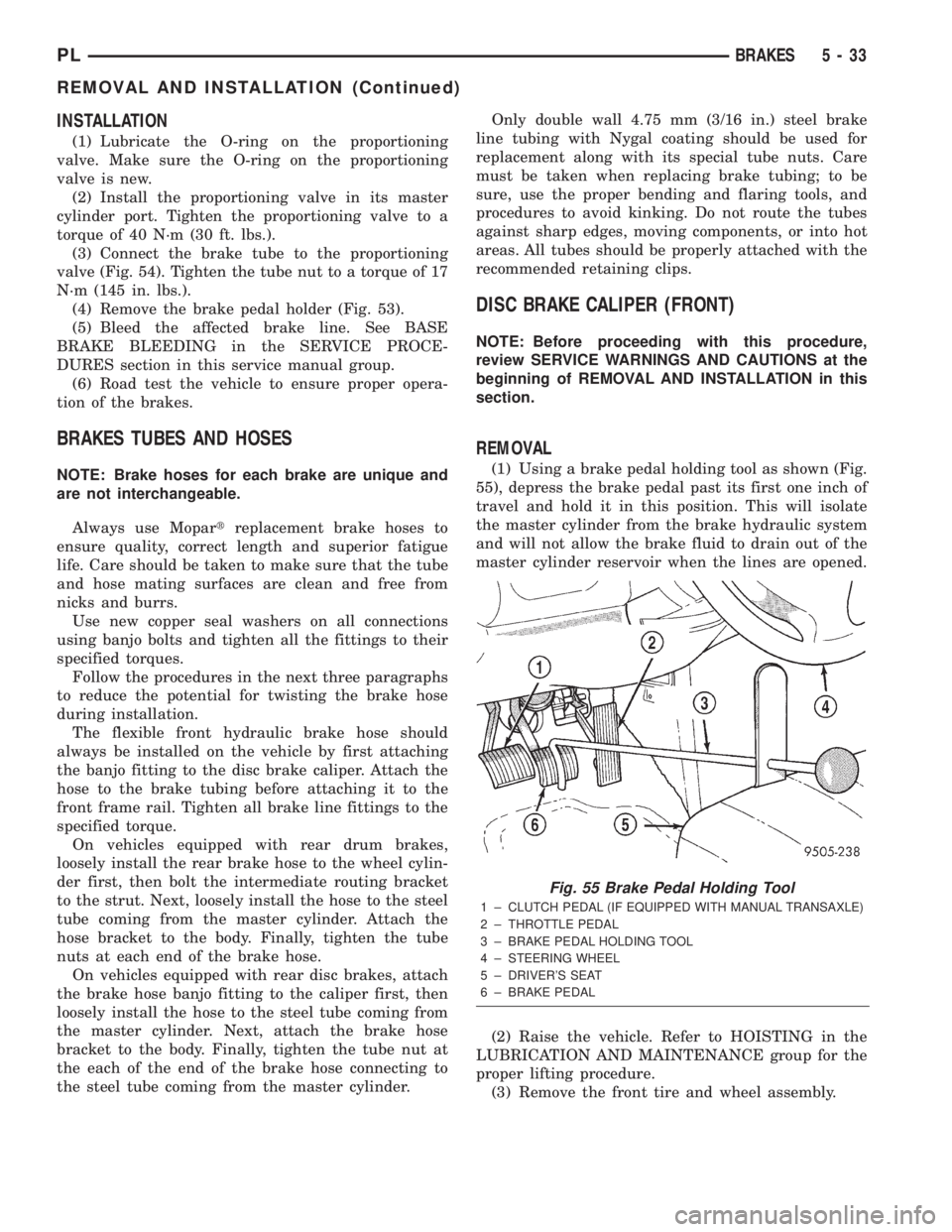
(1) Using a brake pedal holding tool as shown (Fig.
55), depress the brake pedal past its first one inch of
travel and hold it in this position. This will isolate
the master cylinder from the brake hydraulic system
and will not allow the brake fluid to drain out of the
master cylinder reservoir when the lines are opened.
(2) Raise the vehicle. Refer to HOISTING in the
LUBRICATION AND MAINTENANCE group for the
proper lifting procedure.
(3) Remove the front tire and wheel assembly.
Fig. 55 Brake Pedal Holding Tool
1 ± CLUTCH PEDAL (IF EQUIPPED WITH MANUAL TRANSAXLE)
2 ± THROTTLE PEDAL
3 ± BRAKE PEDAL HOLDING TOOL
4 ± STEERING WHEEL
5 ± DRIVER'S SEAT
6 ± BRAKE PEDAL
PLBRAKES 5 - 33
REMOVAL AND INSTALLATION (Continued)
Page 117 of 1285
DISC BRAKE CALIPER (REAR)
REMOVAL
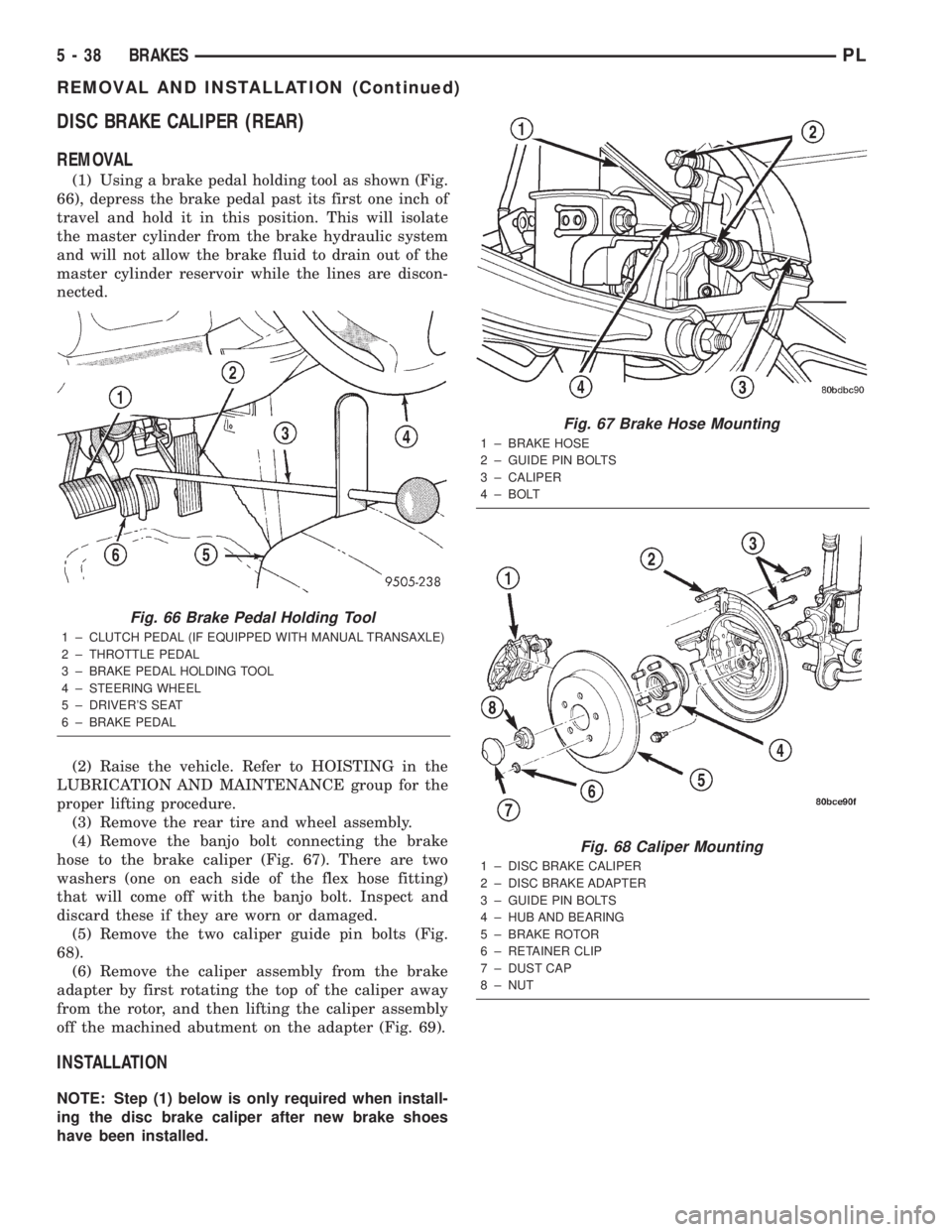
(1) Using a brake pedal holding tool as shown (Fig.
66), depress the brake pedal past its first one inch of
travel and hold it in this position. This will isolate
the master cylinder from the brake hydraulic system
and will not allow the brake fluid to drain out of the
master cylinder reservoir while the lines are discon-
nected.
(2) Raise the vehicle. Refer to HOISTING in the
LUBRICATION AND MAINTENANCE group for the
proper lifting procedure.
(3) Remove the rear tire and wheel assembly.
(4) Remove the banjo bolt connecting the brake
hose to the brake caliper (Fig. 67). There are two
washers (one on each side of the flex hose fitting)
that will come off with the banjo bolt. Inspect and
discard these if they are worn or damaged.
(5) Remove the two caliper guide pin bolts (Fig.
68).
(6) Remove the caliper assembly from the brake
adapter by first rotating the top of the caliper away
from the rotor, and then lifting the caliper assembly
off the machined abutment on the adapter (Fig. 69).
INSTALLATION
NOTE: Step (1) below is only required when install-
ing the disc brake caliper after new brake shoes
have been installed.
Fig. 66 Brake Pedal Holding Tool
1 ± CLUTCH PEDAL (IF EQUIPPED WITH MANUAL TRANSAXLE)
2 ± THROTTLE PEDAL
3 ± BRAKE PEDAL HOLDING TOOL
4 ± STEERING WHEEL
5 ± DRIVER'S SEAT
6 ± BRAKE PEDAL
Fig. 67 Brake Hose Mounting
1 ± BRAKE HOSE
2 ± GUIDE PIN BOLTS
3 ± CALIPER
4 ± BOLT
Fig. 68 Caliper Mounting
1 ± DISC BRAKE CALIPER
2 ± DISC BRAKE ADAPTER
3 ± GUIDE PIN BOLTS
4 ± HUB AND BEARING
5 ± BRAKE ROTOR
6 ± RETAINER CLIP
7 ± DUST CAP
8 ± NUT
5 - 38 BRAKESPL
REMOVAL AND INSTALLATION (Continued)
Page 305 of 1285
WINDSHIELD WASHER SYSTEM
TABLE OF CONTENTS
page page
DESCRIPTION AND OPERATION
WINDSHIELD WASHER NOZZLE(S)............8
WINDSHIELD WASHER SYSTEM.............8
DIAGNOSIS AND TESTING
WINDSHIELD WASHER SYSTEM.............9REMOVAL AND INSTALLATION
WINDSHIELD WASHER HOSE................9
WINDSHIELD WASHER NOZZLES.............9
WINDSHIELD WASHER RESERVOIR..........10
WINDSHIELD WASHER PUMP...............10
DESCRIPTION AND OPERATION
WINDSHIELD WASHER NOZZLE(S)
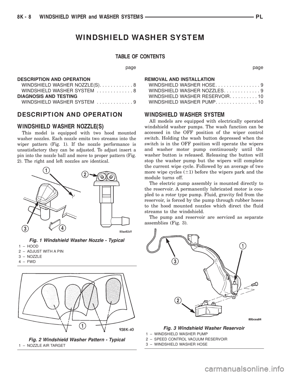
This model is equipped with two hood mounted
washer nozzles. Each nozzle emits two streams into the
wiper pattern (Fig. 1). If the nozzle performance is
unsatisfactory they can be adjusted. To adjust insert a
pin into the nozzle ball and move to proper pattern (Fig.
2). The right and left nozzles are identical.
WINDSHIELD WASHER SYSTEM
All models are equipped with electrically operated
windshield washer pumps. The wash function can be
accessed in the OFF position of the wiper control
switch. Holding the wash button depressed when the
switch is in the OFF position will operate the wipers
and washer motor pump continuously until the
washer button is released. Releasing the button will
stop the washer pump but the wipers will complete
the current wipe cycle. Followed by an average of two
more wipe cycles (61) before the wipers park and the
module turns off.
The electric pump assembly is mounted directly to
the reservoir. A permanently lubricated motor is cou-
pled to a rotor type pump. Fluid, gravity fed from the
reservoir, is forced by the pump through rubber hoses
to the hood mounted nozzles which direct the fluid
streams to the windshield.
The pump and reservoir are serviced as separate
assemblies (Fig. 3).
Fig. 1 Windshield Washer Nozzle - Typical
1 ± HOOD
2 ± ADJUST WITH A PIN
3 ± NOZZLE
4 ± FWD
Fig. 2 Windshield Washer Pattern - Typical
1 ± NOZZLE AIR TARGET
Fig. 3 Windshield Washer Reservoir
1 ± WINDSHIELD WASHER PUMP
2 ± SPEED CONTROL VACUUM RESERVOIR
3 ± WINDSHIELD WASHER HOSE
8K - 8 WINDSHIELD WIPER and WASHER SYSTEMSPL
Page 306 of 1285
DIAGNOSIS AND TESTING
WINDSHIELD WASHER SYSTEM
Whenever a windshield washer malfunction occurs,
first verify that the windshield washer wire harnessis properly connected to all connectors before starting
normal diagnosis and repair procedures. Refer to
Windshield Washer System Test table.
WINDSHIELD WASHER SYSTEM TEST
CONDITION POSSIBLE CAUSE CORRECTION
PUMP RUNS NO FLUID
FLOWING.1. NO FLUID IN THE
RESERVOIR.
2. NOZZLE PLUGGED
OR FROZEN.
3. BROKEN, LOOSE OR
PINCHED HOSE.
4. FAULTY PUMP.1. FILL RESERVOIR.
2. THAW AND CHECK FLOW IF BLOCKED
3. CHECK FLOW THROUGH HOSE CONNECTIONS.
4. APPLY BATTERY VOLTAGE TO MOTOR
TERMINALS, REPLACE IF PUMP DOES NOT RUN.
SYSTEM OPERATES
INTERMITTENTLY.1. LOOSE WIRE
CONNECTION.
2. FAULTY SWITCH.1. CHECK WIRE CONNECTIONS.
2. DISCONNECT WIRE HARNESS USE
VOLTMETER TO CHECK SWITCH.
SYSTEM OUTPUT IS
LOW.1. PINCHED HOSE.
2. HOSE BLOCKED.1. CHECK FLOW THROUGH HOSE CONNECTION.
2. DISCONNECT HOSE AT NOZZLE AND Y
CONNECTOR CHECK FOR FLOW. REPLACE ASS
NECESSARY.
REMOVAL AND INSTALLATION
WINDSHIELD WASHER HOSE
REMOVAL
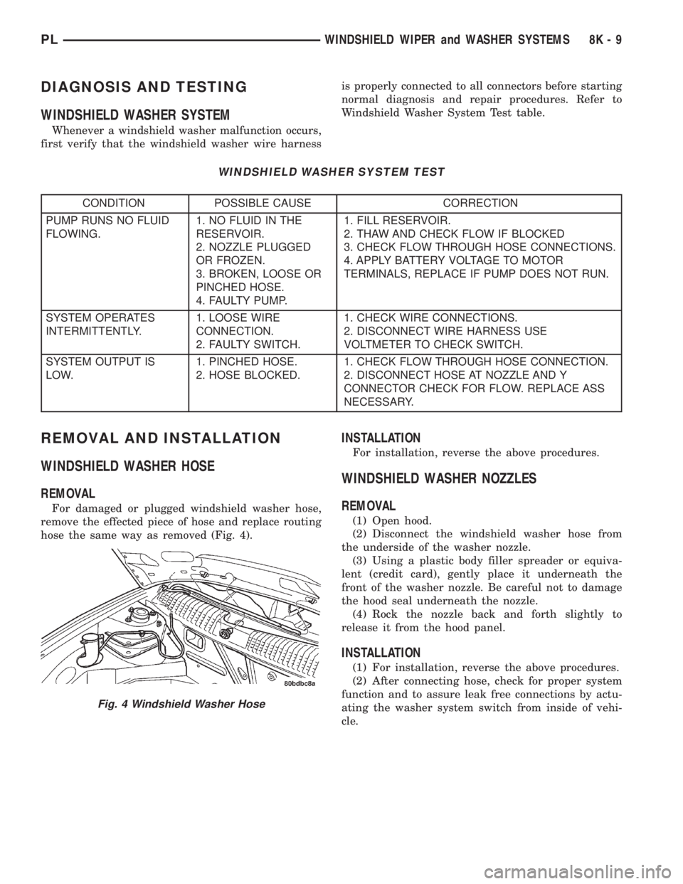
For damaged or plugged windshield washer hose,
remove the effected piece of hose and replace routing
hose the same way as removed (Fig. 4).
INSTALLATION
For installation, reverse the above procedures.
WINDSHIELD WASHER NOZZLES
REMOVAL
(1) Open hood.
(2) Disconnect the windshield washer hose from
the underside of the washer nozzle.
(3) Using a plastic body filler spreader or equiva-
lent (credit card), gently place it underneath the
front of the washer nozzle. Be careful not to damage
the hood seal underneath the nozzle.
(4) Rock the nozzle back and forth slightly to
release it from the hood panel.
INSTALLATION
(1) For installation, reverse the above procedures.
(2) After connecting hose, check for proper system
function and to assure leak free connections by actu-
ating the washer system switch from inside of vehi-
cle.
Fig. 4 Windshield Washer Hose
PLWINDSHIELD WIPER and WASHER SYSTEMS 8K - 9
Page 1063 of 1285
SPECIFICATIONS
31TH AUTOMATIC TRANSAXLE
Type .........Automatic three speed with torque
converter and integral differential
Torque Converter Diameter...... 241millimeters
(9.48 in.)
OilType .....................MopartATF+4
(Automatic Transmission Fluid) Type 9602
Cooling Method.... Water Heat Exchanger and/or
air to oil heat exchanger
Lubrication . . . Pump (internal-external gear-type)
Transmission Gear Ratios
First Gear............................2.69
Second Gear...........................1.55
Third Gear............................1.00
Reverse Gear..........................2.10
Band Adjustment
KickdownÐBacked Off From 8 N²m
(72 in. lbs.).................... 21/4Turns
Low-ReverseÐBacked Off From 5 N²m
(41 in. lbs.).................... 31/2Turns
Clutch Pack Clearances
Front Clutch (Not Adjustable)......1.27-2.79mm
(0.050-0.110 in.)
Rear Clutch.......0.71-1.10mm (0.028-0.043 in.)
End Play
Input Shaft........0.19±1.50 mm (.008±.060 in.)
Front Clutch Retainer...........0.76±2.69 mm
(.030±.106 in.)
Front Carrier.......0.89±1.45 mm (.007±.057 in.)
Front Annulus Gear . . 0.09±0.50 mm (.0035±.020 in.)
Planet Pinion.......0.15±0.59 mm (.006±.023 in.)
Reverse Drum......0.76±3.36 mm (.030±.132 in.)
Oil Pump Clearances
Outer Gear To Pocket...........0.045-0.141mm
(0.0018-0.0056 in.)
Outer Gear Side Clearance.......0.020-0.046mm
(0.0008-0.0018 in.)
Inner Gear Side Clearance.......0.020-0.046mm
(0.0008-0.0018 in.)
Tapered Roller Bearing Settings
Differential Assembly . . 6 to 12 in. lbs. Drag Torque
Output Hub.......... 0to3in.lbs. Drag Torque
Transfer Shaft.......0.002 to 0.010 in. End Play
Overall Drag At Output
Hub ............. 3to16in.lbs. Drag TorqueThrust Washers
Reaction Shaft Support (No. 1).....1.55±1.60 mm
(.061±.063 in.)
Rear Clutch Retainer (No. 2)......1.55±1.60 mm
(.061±.063 in.)
Output Shaft (No. 3) (Select)......1.98±2.03 mm
(.077±.080 in.)
Output Shaft (No. 3) (Select)......2.15±2.22 mm
(.085±.087 in.)
Output Shaft (No. 3) (Select)......2.34±2.41 mm
(.092±.095 in.)
Front Annulus (No. 4)............2.95±3.05 mm
(.116±.120 in.)
Front Carrier (Nos. 5&6).........1.22±1.28 mm
(.0948±.050 in.)
Sun Gear-Front (No. 7)...........0.85±0.91 mm
(.033±.036 in.)
Sun Gear-Rear (No. 8)...........0.85±0.91 mm
(.033±.036 in.)
Rear Carrier (Nos. 9&10).........1.22±1.28 mm
(.0948±.050 in.)
Rev. Drum (No. 11) . . 1.55±1.60 mm (.061±.063 in.)
31TH TRANSAXLE TORQUE SPECIFICATIONS
DESCRIPTION TORQUE
Bell Housing Cover Bolts.... 12N´m(105 in. lbs.)
Cooler Line Clamps.......... 2N´m(18in.lbs.)
Diff. Bear. Ret. To Case Bolt . . 34 N´m (300 in. lbs.)
Diff. Cover To Case Bolt..... 19N´m(165 in. lbs.)
Exten. Hous. To Case Bolt . . . 28 N´m (250 in. lbs.)
Drive Plate To Crankshaft
Bolts................... 95N´m(70ft.lbs.)
Drive Plate To Torque Conv.
Bolts................... 88N´m(65ft.lbs.)
Fluid Filter Screw........... 5N´m(45in.lbs.)
Governor Counterweight
Screw................. 28N´m(250 in. lbs.)
Governor To Support Bolt...... 7N´m(60in.lbs.)
Kickdown Band Adj. Lock Nut . . 47 N´m (35 ft. lbs.)
Left Motor Mount Bolts....... 54N´m(40ft.lbs.)
Manual Cable To Trans.
Case Bolt.............. 28N´m(250 in. lbs.)
Manual Control Lever Screw . . 12 N´m (105 in. lbs.)
Oil Pan To Trans. Case
Screw................. 19N´m(165 in. lbs.)
Output Gear Strap Bolts...... 23N´m(17ft.lbs.)
Output Shaft Nut......... 271N´m(200 ft. lbs.)
Park/Neutral Switch......... 34N´m(25ft.lbs.)
Pressure Check Plug......... 5N´m(45in.lbs.)
Pump To Case Bolts........ 31N´m(275 in. lbs.)
Reaction Shaft Assembly
Bolt................... 28N´m(250 in. lbs.)
Rear Cover To Case Screw . . . 19 N´m (165 in. lbs.)
Reverse Band Adj. Lock Nut . . 14 N´m (125 in. lbs.)
21 - 150 TRANSAXLEPL
Page 1236 of 1285
A/C SERVICE PORT VALVE CORES
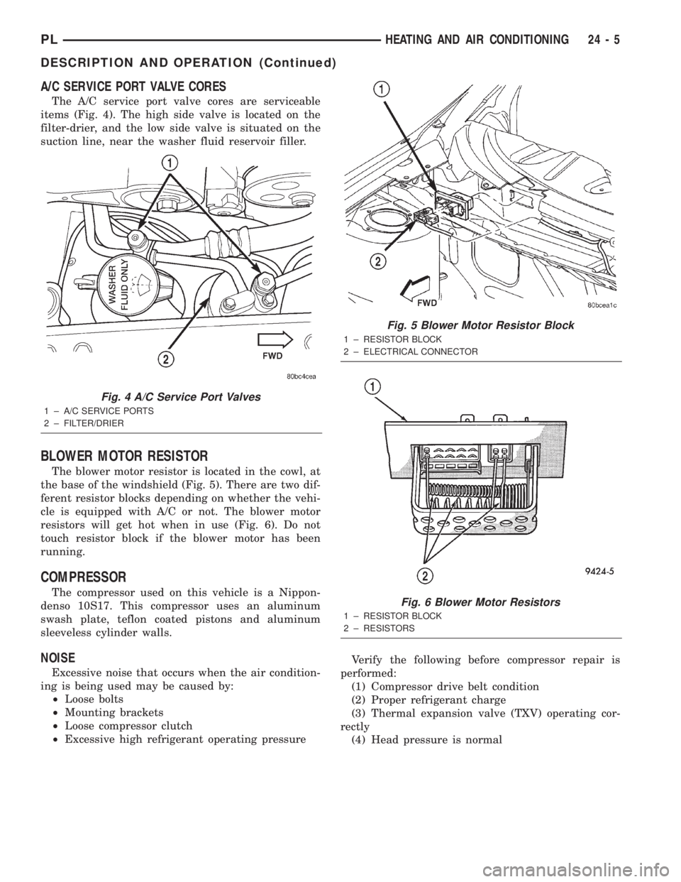
The A/C service port valve cores are serviceable
items (Fig. 4). The high side valve is located on the
filter-drier, and the low side valve is situated on the
suction line, near the washer fluid reservoir filler.
BLOWER MOTOR RESISTOR
The blower motor resistor is located in the cowl, at
the base of the windshield (Fig. 5). There are two dif-
ferent resistor blocks depending on whether the vehi-
cle is equipped with A/C or not. The blower motor
resistors will get hot when in use (Fig. 6). Do not
touch resistor block if the blower motor has been
running.
COMPRESSOR
The compressor used on this vehicle is a Nippon-
denso 10S17. This compressor uses an aluminum
swash plate, teflon coated pistons and aluminum
sleeveless cylinder walls.
NOISE
Excessive noise that occurs when the air condition-
ing is being used may be caused by:
²Loose bolts
²Mounting brackets
²Loose compressor clutch
²Excessive high refrigerant operating pressureVerify the following before compressor repair is
performed:
(1) Compressor drive belt condition
(2) Proper refrigerant charge
(3) Thermal expansion valve (TXV) operating cor-
rectly
(4) Head pressure is normal
Fig. 4 A/C Service Port Valves
1 ± A/C SERVICE PORTS
2 ± FILTER/DRIER
Fig. 5 Blower Motor Resistor Block
1 ± RESISTOR BLOCK
2 ± ELECTRICAL CONNECTOR
Fig. 6 Blower Motor Resistors
1 ± RESISTOR BLOCK
2 ± RESISTORS
PLHEATING AND AIR CONDITIONING 24 - 5
DESCRIPTION AND OPERATION (Continued)